
Filter Circuit
Index 13
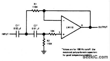
SECOND_ORDER___HIGH_PASS_ACTIVE_FILTER___
Published:2009/6/30 2:07:00 Author:May
View full Circuit Diagram | Comments | Reading(827)
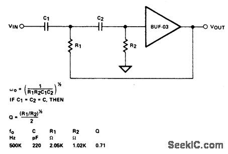
HIGH_PASS_FILTER(HIGH_FREQUENCY)
Published:2009/6/30 2:04:00 Author:May
View full Circuit Diagram | Comments | Reading(615)
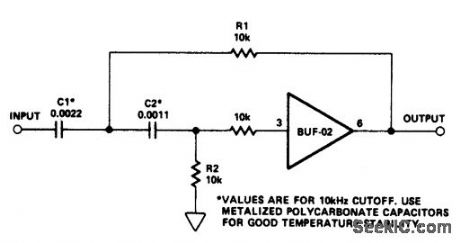
HIGH_PASS_ACTIVE_FILTER
Published:2009/6/30 2:03:00 Author:May
View full Circuit Diagram | Comments | Reading(0)
01_Hz_TO_10_Hz_BANDPASS_FILTER
Published:2009/6/30 2:03:00 Author:May
View full Circuit Diagram | Comments | Reading(979)
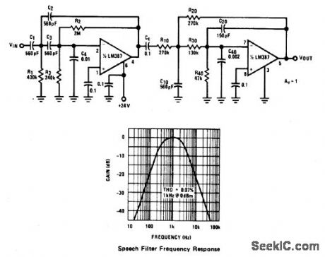
SPEECH_FILTER(300_Hz3_kHz_BANDPASS)
Published:2009/6/30 2:02:00 Author:May
View full Circuit Diagram | Comments | Reading(1151)
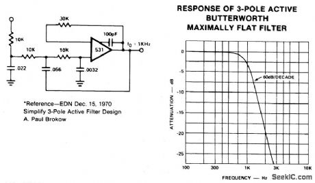
POLE_ACTIVE_LOW_PASS_FILTER(B_UTTERWORTH_MAXIMALLY_FLAT_RESPONSE)
Published:2009/6/30 2:00:00 Author:May
View full Circuit Diagram | Comments | Reading(794)
SPEECH_FILTER
Published:2009/6/30 1:40:00 Author:May
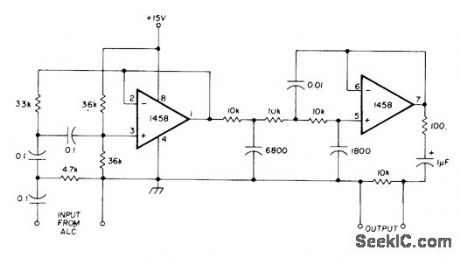
Pair of Bessel-type high-pass filters removes undesired components created by peak clipping during audio signal processing, Developed for use with automatic level control applications of NE571 analog compandor.-W.G. Jung, Gain Control IC for Audio Signal Pro-cessing, Ham Radio, July 1977, p 47-53. (View)
View full Circuit Diagram | Comments | Reading(2348)
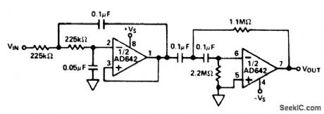
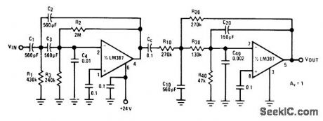
AUDIO_FILTERS_FOR_SNR_MEASUREMENT
Published:2009/6/30 Author:May
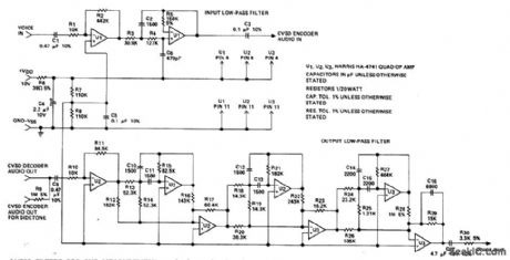
Used in checking performance of Harris HC-55516/55532 haff-duplex modulator-demodulator systems for converting voice signals into s rial NRZ digital data and reconverting that data back to voice. Supply required for opamp sections is ±15 V. Response of input filter is down 3 dB at 3 kHz and is down 20 dB at 9 kHz. Response of output filter is flat up to 3 kHz and down more than 45 dB from 3.8 kHz to 100kHz.- Linear & Data Acquisition Products, Harris Semiconductor,Melbourne,FL,Vol.1,1977,p 5-10. (View)
View full Circuit Diagram | Comments | Reading(739)
SPEECH_FlLTER
Published:2009/6/29 23:56:00 Author:May
High-pass and low pass filters in cascade provide comer frequencies of 300 and 3000 Hz for limiting audio bandwidth to speech frequencies. Rolloff beyond corners is -40 dB per decade. Input-to-output gain is 1.- Audio Handbook, National Semiconductor, Santa Clara, CA, 1977, p 2-49-2-52. (View)
View full Circuit Diagram | Comments | Reading(1254)
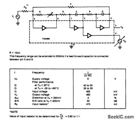
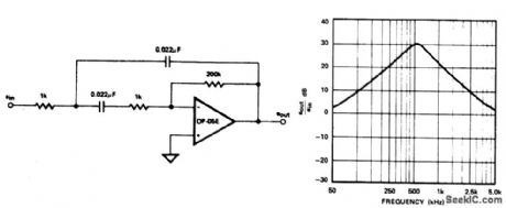
ACTIVE_RC_FILTER_FOR_FREQUENCIES_UP_TO_150_kHz
Published:2009/6/29 23:03:00 Author:May
View full Circuit Diagram | Comments | Reading(648)
TUNABLE_ACTIVE_FILTER
Published:2009/6/29 23:01:00 Author:May
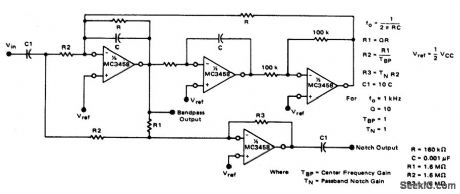
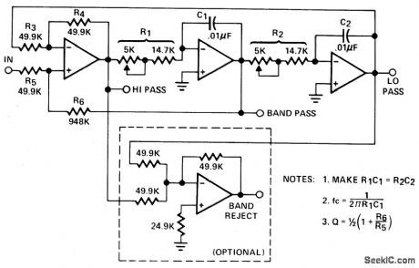
Circuit NotesThe high-pass and low-pass outputs cov-ering the range of 300 Hz to 3000 Hz have been summed in the fourth op amp to provide a notchoutput. The potentiometers must have a re-verse log taper. Fixed-frequency active filter center frequency is1 kHz, with a Q of 50. (View)
View full Circuit Diagram | Comments | Reading(940)
SECOND_ORDER_STATE_VARIABLE_FILTER(1_kHz,Q=10)
Published:2009/6/29 22:56:00 Author:May
View full Circuit Diagram | Comments | Reading(971)
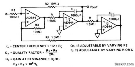
BIQUAD_FILTER
Published:2009/6/29 22:54:00 Author:May
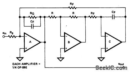
Circuit Notes
The biquad filter, while appearing very similar to the state-variable filter, has a bandwidth that is fixed regardless of center frequency. This type of filter is useful in applications such as spectrum analyzers, which require a filter with a fixed bandwidth. (View)
View full Circuit Diagram | Comments | Reading(1170)
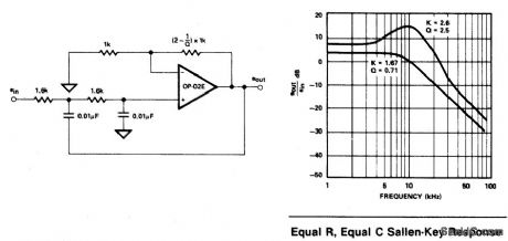
EQUAL_COMPONENT_SALLEN_KEY_LOW_PASS_FILTER
Published:2009/6/29 22:53:00 Author:May
View full Circuit Diagram | Comments | Reading(755)
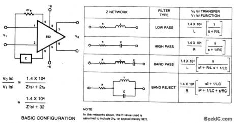
FILTER_NETWORKS
Published:2009/6/29 22:50:00 Author:May
View full Circuit Diagram | Comments | Reading(686)
500_Hz_SALLEN_KEY_BANDPASS_FILTER
Published:2009/6/29 22:48:00 Author:May
View full Circuit Diagram | Comments | Reading(858)
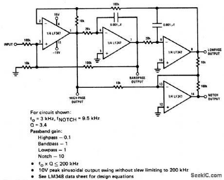
UNIVERSAL_STATE_VARIABLE_FILTER
Published:2009/6/29 21:51:00 Author:May
View full Circuit Diagram | Comments | Reading(0)
BANDPASS_STATE_VARIABLE_FILTER
Published:2009/6/29 21:50:00 Author:May
View full Circuit Diagram | Comments | Reading(712)
Current-voltage converter circuit
Published:2011/7/28 4:24:00 Author:John | Keyword: Current-voltage converter

Current-voltage converter circuit is shown.
(View)
View full Circuit Diagram | Comments | Reading(2725)
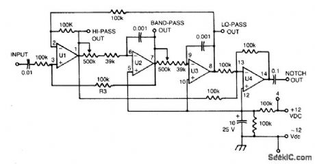
THREE_AMPLIFIER_ACTIVE_FILTER
Published:2009/6/29 21:48:00 Author:May
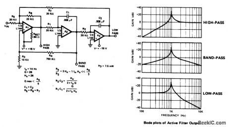
Circuit NotesThe active filter is a state variable filter with bandpass, high-pass and low-pass outputs, It is a classical analog computer method of implementing a filter using three amplifiers and only two capacitors. (View)
View full Circuit Diagram | Comments | Reading(1105)
| Pages:13/21 1234567891011121314151617181920Under 20 |
Circuit Categories
power supply circuit
Amplifier Circuit
Basic Circuit
LED and Light Circuit
Sensor Circuit
Signal Processing
Electrical Equipment Circuit
Control Circuit
Remote Control Circuit
A/D-D/A Converter Circuit
Audio Circuit
Measuring and Test Circuit
Communication Circuit
Computer-Related Circuit
555 Circuit
Automotive Circuit
Repairing Circuit