
Filter Circuit
Index 5
NOTCH_FILTER_CIRCUIT
Published:2009/7/13 10:17:00 Author:May
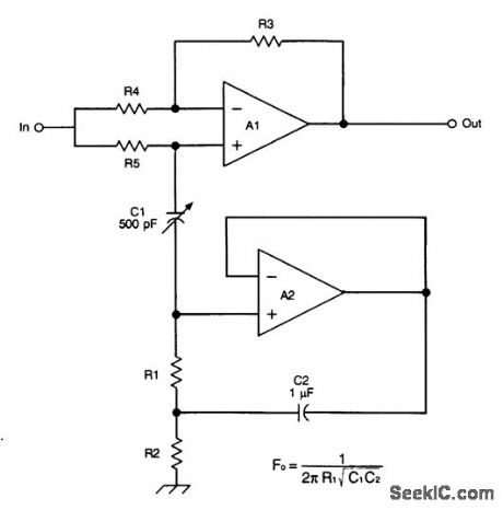
This circuit is basically a noninverting amplifier with positive feedback. The negative feedback path is set to unity by a direct connection between the output terminal of the operational amplifier and the inverting (-) input. A frequency-selective RC network connects the output to the noninverting (+) input, providing some positive feedback. The center frequency is FC=1/2πR1(C1C2)1/2where FC is the center frequency in hertz, R1 is in ohms, and C1 and C2 are in farads. (View)
View full Circuit Diagram | Comments | Reading(1069)
ACTIVE_FILTER_
Published:2009/7/13 10:11:00 Author:May
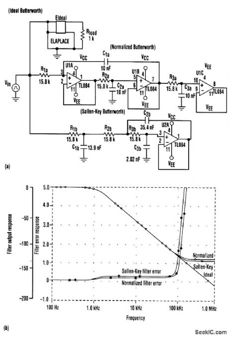
Equal-value components can be quite an advantage in filter designs when the total costs associated with the procurement, stocking, and assembly of the filter are considered. For instance, the Butterworth active third-order low-pass filter (middle) uses equal-value resistors and capacitors. This feature normalizes the filter's 3-dB corner frequency to 1/RC (in radians) for both low-pass and high-pass designs. The graphs in (b) are plots of the ideal, normalized, and Sallen-Key low-pass filter frequency-domain magnitude and error responses. Note how both the normalized and Sallen-Key filters follow the ideal response well into the stopband. The error plots were created by plotting the difference between the real and ideal filter responses. The plots indicate that the normalized filter achieves performance results that are equal to those of the Sallen-Key low-pass filter. (View)
View full Circuit Diagram | Comments | Reading(963)
1_MHz_OR_500_kHz_ELLIPTIC_LP_FILTER
Published:2009/7/13 10:07:00 Author:May
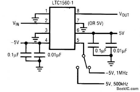
This filter uses a Linear Technology P/N LTC1560-1 to implement a switchable LP filter. (View)
View full Circuit Diagram | Comments | Reading(739)
SW_RECEIVER_CW_FILTER
Published:2009/7/13 10:05:00 Author:May
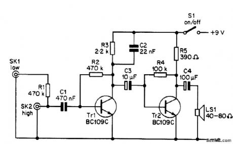
The CW filter is connected between the headphone or loudspeaker socket or terminal strip of your receiver and either the headphones or an external loudspeaker. The output of the receiver should have an intpedance of 8Ω or more. As the circuit provides unity gain at pass frequencies and a low-impedance output, there should be no problems with mismatching when the filter is in use. The frequency response of the circuit peaks at approximately 800 Hz, and the -6-dB bandwidth is about 300 Hz or so. The 0-dB points occur at about 350 Hz and 2 kHz. This is sufficient to normally give a substantial reduction in adjacent-channel interference, but the response is not so narrow and peaky that using the receiver with the filter in the circuit becomes difficult, as the wanted signal tends to drift out of the passband and become lost. (View)
View full Circuit Diagram | Comments | Reading(1113)
HIGH_PASS_LOW_PASS_FILTER
Published:2009/7/13 10:03:00 Author:May
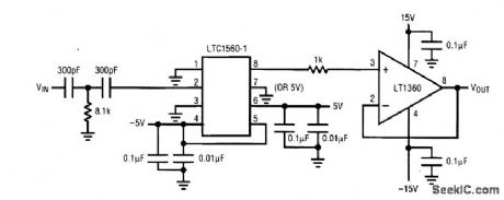
This filter uses a Linear Technology P/N LTC1560-1 and an LT1360 to implement a high-pass/low-pass filter. (View)
View full Circuit Diagram | Comments | Reading(909)
AMATEUR_TRANSMITTER_ABSORPTIVE_FILTER
Published:2009/7/13 10:00:00 Author:May
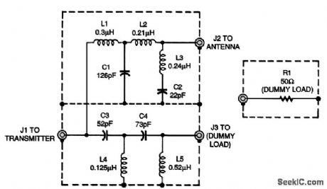
This filter diverts harmonic energy above 30 MHz to a dummy load and dissipates it as heat instead of reflecting it back to the transmitter. The absorptive filter is based on the classic design by Weinreich and Carroll from 1968. The high-pass and low-pass sections are shielded from each other (even though they are in the same shielded box) to prevent interaction. If you want to try building this filter, wind the coils on high-powered toroids. Alternatively, you could wind an air-core coil using the nomograms in The ARRL Handbook for Radio Amateurs. (View)
View full Circuit Diagram | Comments | Reading(764)
PEAKING_FILTER_CIRCUIT
Published:2009/7/13 9:54:00 Author:May
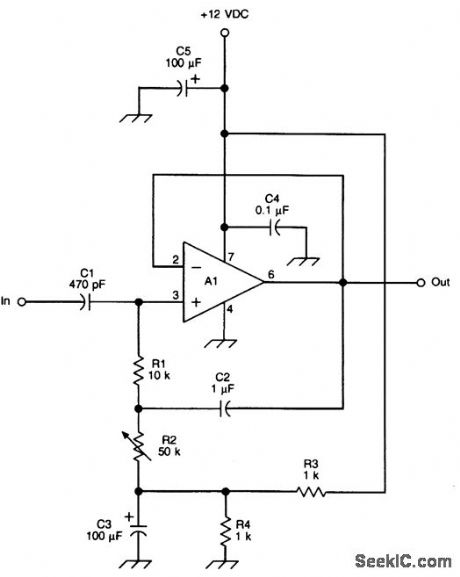
This circuit is basically a noninverting amplifier with positive feedback. The negative feedback is to unity by a direct connection between the output terminal of the operational amplifier and the inverting (-) input. A frequency-selective RC network connects the output to the noninverting (+) input, providing some positive feedback. The center frequency is FC=1/2πR1(C1C2)1/2where FC is the center frequency in hertz, R1 is in ohms, and C1 and C2 are in farads. (View)
View full Circuit Diagram | Comments | Reading(1013)
AUDIO_CLIPPER_FILTER
Published:2009/7/13 4:52:00 Author:May
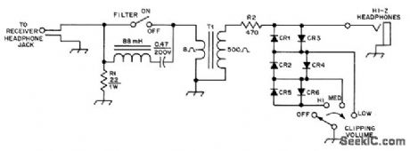
Improves seleetivity of communication receiver and prevents uncomfortablv loud volume in 500-ohm headphones. 88-mH toroid and 0.47-μF capaeitor form series resonant circuit at about 750 Hz with 6-dB bandwidth of 75 Hz. R2 and diodes form audio clipperwhose level is determined by forward conduction voltage of diodes. With ger-manium diodes for CR1-CR4 and silicon for CR5-CR6, each successive switch position boosts volume 6 dB. For low-impedance headphones, omit T1 and use 8 ohms for R2.-A, R Bloom, An Audio Clipper/Filter, QST, Aug. 1977, p 48. (View)
View full Circuit Diagram | Comments | Reading(1005)
PASSIVE_CW_FILTER
Published:2009/7/11 5:05:00 Author:May
Uses inexpensive 88-mH toroids to give very sharp 35-Hz bandwidth at 3 dB down. Filter has high insertion loss. Keyed waveshape has slow rise and fall, so CW signals have pronounced ringing that may be objec-tionable.-A. F. Stahler, An Experimental Com-parison of CW Audio Filters, 73 Magazine, July 1973, p 65-70. (View)
View full Circuit Diagram | Comments | Reading(1661)
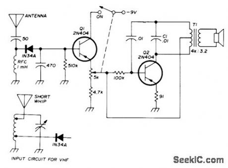
144_MHz_T0_28_MHz
Published:2009/7/11 4:58:00 Author:May
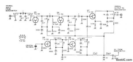
144 MHz T0 28 MHz-Contains bandpass filter, grounded-grid RF amplifier stages Q5- Q6, mixer Q7, and crystal oscillator Q8-Q9. Developed for use in all-band double- conversion superheterodyne receiver for AM, narrow-band FM, CW, and SSB operation. Supply is 13.6 V regulated. Article gives all circuits of receiver-D. M. Eisen. berg, Build This All-Band VHF Receiver, 73 Magazine, Jan. 1975, p 105-112. (View)
View full Circuit Diagram | Comments | Reading(3650)
CW_STEREO_FILTER
Published:2009/7/11 4:35:00 Author:May
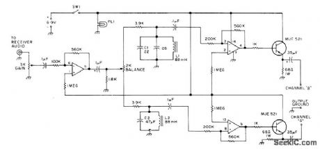
Developed to enhance ability to read CW despite heavy contest traffic or other QRM. Two high-Q filters, one at each end of 400-Hz CW filter in receiver, create separate audio channels to give effect of stereo.Transistors at outputs of channels provide extra current gain for driving low-impedance stereo headphones. CW signal at 800 Hz then appears to comefrom left, 1200-Hz signal from right, and in between frequencies at various azimuth angles. Illusion of direction makes it easier for operator to concentrate on desired signal in presonce of others having slightly different frequencies. L1 and C1 form filter for 1200-Hz channel, while L2 and C2 form 800-Hz filter for other channel.-R. L. Anderson, Stereo-a New Type of CW Filter, 73 Magazine, March 1976, p 48-50. (View)
View full Circuit Diagram | Comments | Reading(940)
CW_FILTER_1
Published:2009/7/11 3:28:00 Author:May
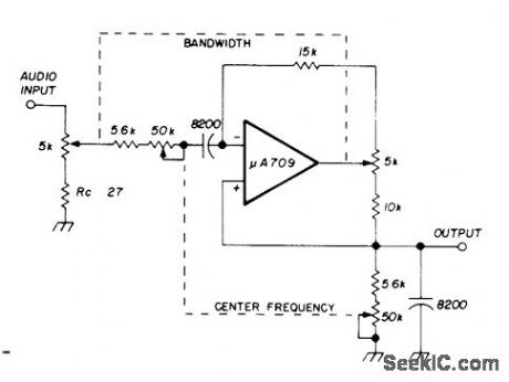
Variable-bandwidth variable-frequency audio filter can be tuned to center frequency anywhere in range from 300 to 3000 Hz.Bandwidth can be as narrow as 50 Hz, which is about 3 times theoretical minimum of is Hz for 50-bit words and Morse code at 25 WPM. Performance can be improved over entire fre-quency range by using 741 opamp.-R. Skelton, Comments, Ham Radio, June 1975, p 56-57. (View)
View full Circuit Diagram | Comments | Reading(922)
REGENERATIVE_CW_FILTER
Published:2009/7/11 3:06:00 Author:May
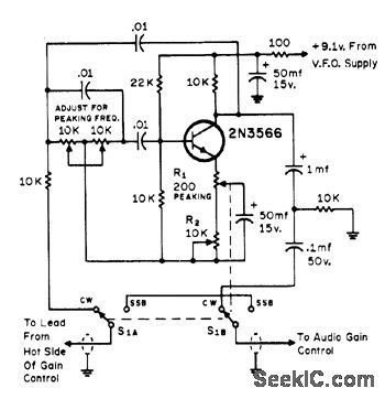
Can be added between product detector and volume control of SSB receiver or transceiver that does not have CW filter. Just before oscillation oceurs, gain becomes extremely high with very narrow bandpass. Regeneration and bandpass can be adjusted as required. Filter typically has 40-Hz bandwidth centered on 800 Hz.-R. A. Yoemans, Further Enhancing the Yaesu FTDX-560 Transceiver, CQ, July 1972, p 16-18 and 20-22. (View)
View full Circuit Diagram | Comments | Reading(1618)
CW_FILTER
Published:2009/7/11 3:05:00 Author:May
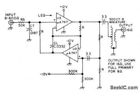
Simple single-section parallel-tuned active filter uses negative-impedance converter or gyrator to replace hard-to-get inductor of passive code filter. Capacitor CL is gyrated from 0.0332 ptF to effective inductance of 1.87 H. Filter has 6-dB gain at resonance and essentially zero output impedance. Bandpass is 85 Hz centered at about 865 Hz. Uses single -12 V supply. Resistors R are 7.5K, matched to about 2%.-N. Sipkes, Build This CW Filter, 73 Mag-azine, June 1977, p 55. (View)
View full Circuit Diagram | Comments | Reading(1018)
FILTERED_SAMPLE_AND_HOLD
Published:2009/7/9 23:12:00 Author:May
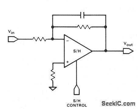
It is often required that a signal be filtered pnor to sampling. This can be accomplished with only one device. Use any of the inverting and noninverting filters that can be built with op amps. However, it is necessary that the sampling switch be closed for a sufficient time for the filter to settle when active filter types are connected around the device. (View)
View full Circuit Diagram | Comments | Reading(816)
PSEUDORANDOM_SIMULATED_FLICKER_SEQUENCER
Published:2009/7/9 1:48:00 Author:May
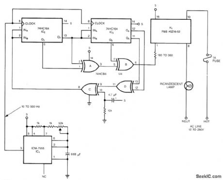
The pseudorandom sequencer drives a solid-state relay, If you power a low-wattage lamp from the relay, the lamp will appear to flicker like a candle’s flame in the wind; using higher-wattage lamps allows you to simulate the blaze of a fireplace or campfire. You can enhance the effect by using three or more such circuits to power an array of lamps. The circuit comprises an oscillator, IC1, and a 15-stage, pseudorandom sequencer, IC2-4. The sequencer produces a serial bit stream that repeats only every 32767 bits. Feedback from the sequenc-er’s stages 14 and 15 go through IC4D and back to the serial input of IC2. Notice the RC network that feeds IC4C; the network feeds a positive pulse into the sequencer to ensure that it won’t get stuck with all zeros at power-up. The leftover XOR gates IC4A and IC4B further scramble the pattern. The serial stream from IC4B drives a solid-state relay that features zero-voltage switching and can handle loads as high as 1A at 12 to 280 Vac. (View)
View full Circuit Diagram | Comments | Reading(831)
TWO_SALLEN_KEY_LOW_PASS_ACTIVE_FILTERS
Published:2009/7/9 1:43:00 Author:May
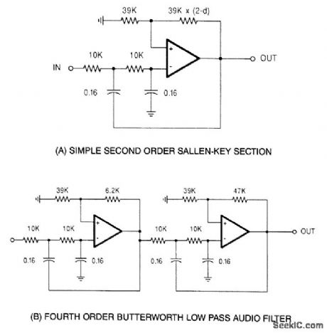
These filters are designed for 10-kΩ impedance level and 1-kHz cutoff frequency, but the components can be scaled as required for other impedances and cutoff frequencies. (View)
View full Circuit Diagram | Comments | Reading(998)
1000_1_TUNING_VOLTAGE_VOLTAGE_CONTROLLED_FILTER
Published:2009/7/9 1:39:00 Author:May
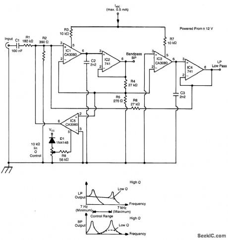
A standard dual integrator ftlter can be constructed using a few CA3080s. By varying IABC, the reso-nant frequency can be swept over a 1000:1 range. At IC1, three are current-controlled integrators. At IC2, four are voltage followers that serve to buffer the high-impedance outputs of the integrators. A third CA3080 (IC5) is used to control the Q factor of the filter. The resonant frequency of the ftlter is linearly proportional to IABC. Hence, this unit is very useful in producing electronic music. Two outputs are pro-duced: a low-pass and a bandpass response. (View)
View full Circuit Diagram | Comments | Reading(866)
SIMPLE_RUMBLE_FILTER
Published:2009/7/9 1:35:00 Author:May
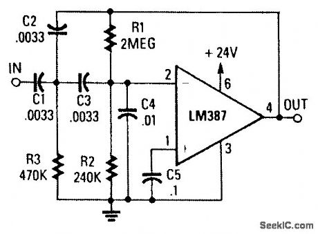
This circuit is a two-section active HP filter using an LM387, with a cutoff below 50 Hz at 12-dB per octave. It will help reduce rumble as a result of turntable defects in record systems. (View)
View full Circuit Diagram | Comments | Reading(911)
FOURTH_ORDER_100_Hz_HIGH_PASS_FILTER
Published:2009/7/9 0:05:00 Author:May
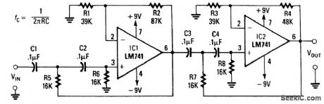
This filter, using two sections of LM741, can be scaled in frequency ,If desired. (View)
View full Circuit Diagram | Comments | Reading(1232)
| Pages:5/21 1234567891011121314151617181920Under 20 |
Circuit Categories
power supply circuit
Amplifier Circuit
Basic Circuit
LED and Light Circuit
Sensor Circuit
Signal Processing
Electrical Equipment Circuit
Control Circuit
Remote Control Circuit
A/D-D/A Converter Circuit
Audio Circuit
Measuring and Test Circuit
Communication Circuit
Computer-Related Circuit
555 Circuit
Automotive Circuit
Repairing Circuit