
Filter Circuit
Index
Mercedes-Benz 190E external light circuit diagram
Published:2013/12/8 21:13:00 Author:lynne | Keyword: Mercedes-Benz 190E external light circuit diagram,
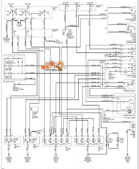
Mercedes-Benz 190E external light circuit diagram is shown below:
(View)
View full Circuit Diagram | Comments | Reading(2041)
Mercedes-Benz 190E GND Ground Distribution Diagram
Published:2013/12/8 21:16:00 Author:lynne | Keyword: Mercedes-Benz 190E GND Ground Distribution Diagram,
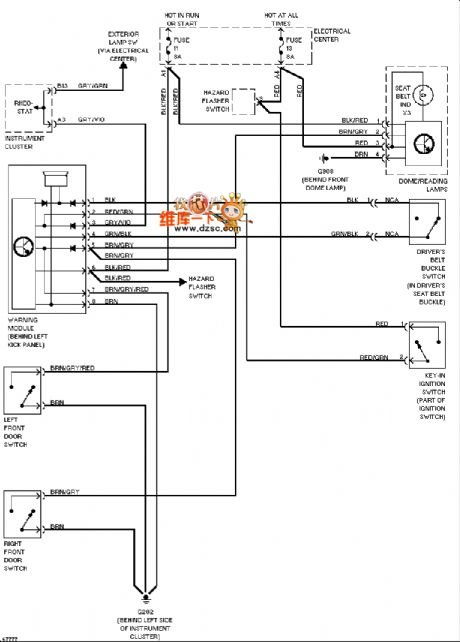
Mercedes-Benz 190E GND Ground distribution diagram is shown below:
(View)
View full Circuit Diagram | Comments | Reading(1494)
Mercedes-Benz 190E headlight circuit (no DRL)
Published:2013/12/8 21:18:00 Author:lynne | Keyword: Mercedes-Benz 190E headlight circuit (no DRL),
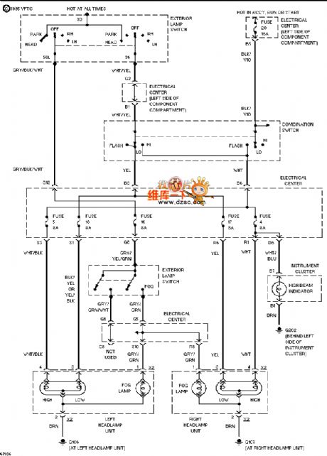
Mercedes-Benz 190E headlight circuit (no DRL) as follows:
(View)
View full Circuit Diagram | Comments | Reading(1175)
Mercedes-Benz 190E seat heater circuit diagram
Published:2013/12/8 21:19:00 Author:lynne | Keyword: Mercedes-Benz 190E seat heater circuit diagram,
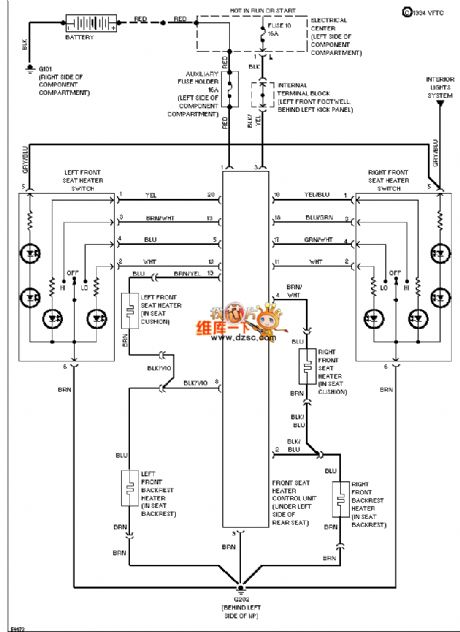
Mercedes-Benz 190E seat heater circuit diagram is shown below:
(View)
View full Circuit Diagram | Comments | Reading(1521)
The three-phase bridge rectifier pop n-type filter circuit
Published:2013/3/28 1:47:00 Author:Ecco | Keyword: three-phase, bridge rectifier , pop n-type filter
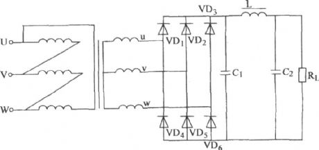
The three-phase bridge rectifier pop n-type filter circuit is shown as figure.
(View)
View full Circuit Diagram | Comments | Reading(1015)
2nd Order Opamp Filters
Published:2013/3/4 20:59:00 Author:Ecco | Keyword: 2nd Order , Opamp , Filters
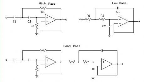
The figures below illustrate using opamps as active 2nd order filters. Three 2nd order filters are shown, low pass, high pass, and bandpass. Each of these filters will attenuate frequencies outside their passband at a rate of 12dB per octave or 1/4 the voltage amplitude for each octave of frequency increase or decrease outside the passband.
First order low or high pass cutoff frequency (-3dB point) = 1/(2pi*R*C) 2nd order low or high pass cutoff frequency (-3dB point) = 1/2pi(R1*R2*C1*C2)^.5 Example for 200 Hz cutoff frequency - R1=R2=7.95K, C1=C2=0.1uF
(View)
View full Circuit Diagram | Comments | Reading(1363)
Band pass filter diagran with operational amplifier
Published:2013/2/18 0:06:00 Author:Ecco | Keyword: Band pass filter, operational amplifier
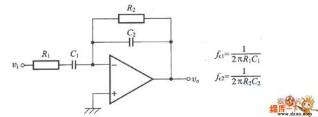
Band pass filter diagran with operational amplifier is shown as figure.
(View)
View full Circuit Diagram | Comments | Reading(1368)
Low-pass filter (Integrator) circuit
Published:2012/10/26 21:03:00 Author:Ecco | Keyword: Low-pass filter, Integrator
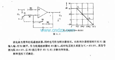
The circuit is a simple low-pass filter, but also can be used as an integrator. When it is used as integrator, switch S1 is connected to input end, while the S2 is disconnected. R3 is connected when it is used as lower filter, amplification coefficient of the voltage VU=R3/R1. The internal resistor Ri of signal source is much less than R1, and R2 value should be equal to the equivalent value of R3 and R1 connected in parallel.
(View)
View full Circuit Diagram | Comments | Reading(1157)
The fourth-order low -pass filter circuit with capacitor element
Published:2012/10/11 21:14:00 Author:Ecco | Keyword: fourth-order, low -pass, filter , capacitor element
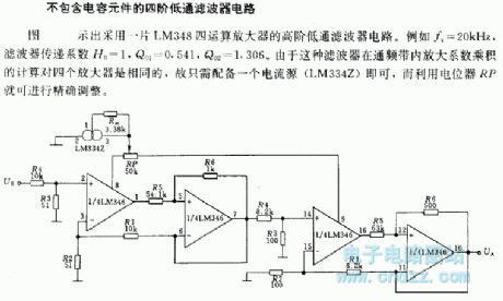
The figure shows a high-order low - pass filter circuit using a LM348 quad operational amplifier. For example fc = 20kHz, filter transfer coefficient H0 = 1, Q01 = 0.541, Q02 = 1.306. Because the amplification coefficient product calculation of filter in the pass band for the four amplifiers is identical, it is simply equipped with a current source (LM334Z), and precise adjustment can be carried out using the potentiometer RP.
(View)
View full Circuit Diagram | Comments | Reading(1276)
Active filter circuit with variable states
Published:2012/9/19 22:38:00 Author:Ecco | Keyword: Active filter , variable states
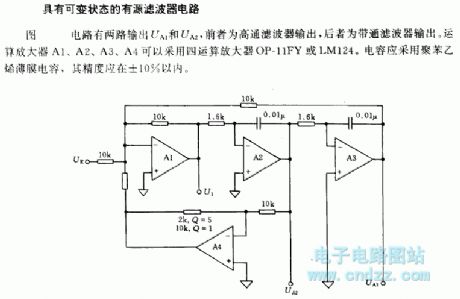
The circuit shown in figure has 2 outputs UA1 and UA2, the former is a high -pass filter output, and the latter is a band-pass filter output. The operational amplifiers A1 , A2 , A3 and A4 can use quad op amp OP-11FY or a LM124. Capacitor should use polystyrene film capacitor, and its accuracy should be less than ± 10%.
(View)
View full Circuit Diagram | Comments | Reading(1204)
High pass filter ( differentiator ) circuit
Published:2012/9/19 22:27:00 Author:Ecco | Keyword: High pass filter, differentiator
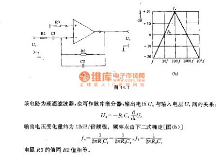
The circuit is the high-pass filter which is also used as pulse differentiator, output voltage is Ua and input voltage is Ue. Output voltage variation is about 12dB / octave. The value of the resistor R3 and R2 is equal.
(View)
View full Circuit Diagram | Comments | Reading(1191)
First-order butterworth active low-pass filter
Published:2012/9/18 21:33:00 Author:Ecco | Keyword: First-order butterworth, active, low-pass filter
Butterworth filter is a type of filter whose frequency response is flat over the passband region. Low-pass filter (LPF) provides a constant output from DC up to a cutoff frequency f(H) and rejects all signals above that frequency. Circuit diagram shown below is a first-order low-pass Butterworth filter that uses RC network for filtering. Loading of the RC network is avoided by using the Op-Amp which is configured for non-inverting mode. Resistors R1 and Rf determine the gain of the filter.
Op-Amp ( 5 terminal )
3 Resistors
1 Capacitor
Voltage sources
Af = 1+Rf/R1
f (H) = 1/(2πRC)
In the above circuit the component XSC1 is the Oscilloscope which is used to verify the circuit so don’t get confused with it. In the above circuit the cutoff frequency is decided the resistor R and capacitor C. You can choose any desired value to fix the cutoff frequency. In the above circuit i choose the cutoff frequency to be approximately 5KHz so i used the resistor R of value 10KΩ and capacitor of value 3nF. You can change it if you want to by using the above cutoff frequency formula.
The first order low-pass filter has a practical slope of -20 dB/decade. The low-pass filter has a constant gain Af from 0 to high cutoff frequency f (H). At f(H) the gain is 0.707Af and after f (H) it decreases at a constant rate of 20 dB/decade. The frequency f = f (H) is called the high cutoff frequency because the gain of the filter at this frequency is down by 3 dB ( =20log(10) 0.707 ) from 0 Hz.
The AC analysis of the above circuit is given below. But it is not exactly for the above circuit. The cutoff frequency is now made 20kHz. For getting cutoff frequency 20kHz you need resistor of value 1KΩ and capacitor of value 7.96nF.
If you have any doubt in the circuit please let us know by comments.
2 Responses to “First-order butterworth active low-pass filter”
(View)
View full Circuit Diagram | Comments | Reading(1049)
Notching filter circuit with variable Q
Published:2012/9/13 22:49:00 Author:Ecco | Keyword: Notching filter , variable Q
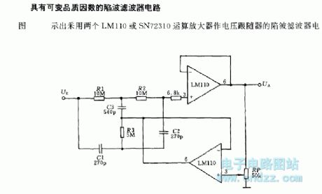
A notch filter circuit with a variable quality factorThe notch filter circuit uses two LM110 or SN72310 operational amplifiers as voltage follower, and the circuit is shown in figure.
(View)
View full Circuit Diagram | Comments | Reading(1224)
Four-stage telecom filter circuit with 1KHZ frequency
Published:2012/9/13 22:43:00 Author:Ecco | Keyword: Four-stage , telecom, filter , 1KHZ frequency

Third-order asymmetric filter circuit has two ways of output UA1 and UA2, the former is high-pass filter output, and the later is low-pass filter output.
(View)
View full Circuit Diagram | Comments | Reading(1417)
Third-order asymmetric filter circuit
Published:2012/9/17 1:34:00 Author:Ecco | Keyword: Third-order , asymmetric, filter
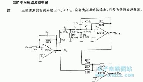
In the figure, thethird-order asymmetric filter has two ways of output UA1 and UA2, the former is high-pass filter output, and the later is the low-pass filter output.
(View)
View full Circuit Diagram | Comments | Reading(981)
Single-phase full-wave rectifier Π filter circuit
Published:2012/9/13 22:39:00 Author:Ecco | Keyword: Single-phase, full-wave, rectifier, Π filter
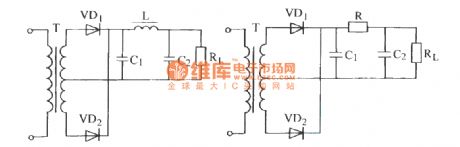
Typically, under the case with low current of the rectifier circuit (several tens mA ) , it may use resistor R with appropriate power, and can reduce the weight of the filter to reduce costs. The circuit is shown in the diagram.
(View)
View full Circuit Diagram | Comments | Reading(1962)
Passive subwoofer filter
Published:2012/9/13 20:38:00 Author:Ecco | Keyword: Passive subwoofer, filter
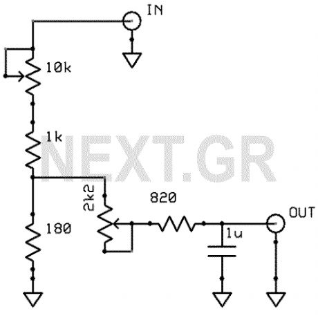
The schematic shown, does no need any power supply because is a simple low frequency passive filter. It could be usefull if you want to drive an extra subwoofer from your stereo system.
Source: NEXT.GR (View)
View full Circuit Diagram | Comments | Reading(0)
Active double secondary band-pass filter circuit
Published:2012/9/13 1:40:00 Author:Ecco | Keyword: Active double, secondary band-pass filter
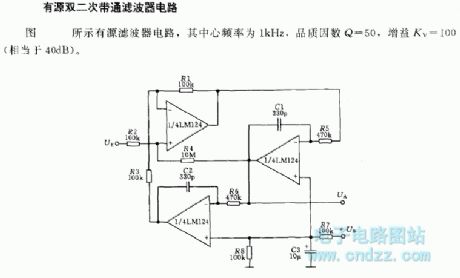
The center frequency is 1kHz, quality factor Q=50, gain KV=100( about 40dB).
(View)
View full Circuit Diagram | Comments | Reading(1060)
Anti-RF filtered power supply 12-14 Volt / 3A
Published:2012/9/12 20:50:00 Author:Ecco | Keyword: Anti-RF , filtered , power supply, 12-14 Volt / 3A
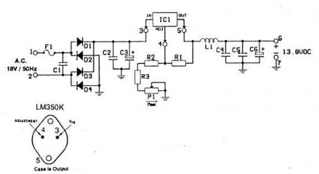
This power supply is dedicated for use with rf equipments like, linear amplifiers, transmitters, receivers, and in every application that clean an-noisy signal is required. The circuit is very simple and you can drive it with a 220V/18V/3A transformer at the pins 1and 2. (View)
View full Circuit Diagram | Comments | Reading(1112)
AUDIO AMP + 3KHz FILTER
Published:2012/9/4 20:10:00 Author:Ecco | Keyword: AUDIO , AMP, + 3KHz , FILTER
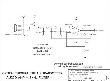
This circuit is the audio amp section for a complete optical transmitter. The circuit amplifies and filters the voice audio signals from an electret microphone. The circuit is described in more detail in the receiver section of Dave Johnson's Handbook of Optical Through the Air Communications.
Source: discovercircuits (View)
View full Circuit Diagram | Comments | Reading(3)
| Pages:1/21 1234567891011121314151617181920Under 20 |
Circuit Categories
power supply circuit
Amplifier Circuit
Basic Circuit
LED and Light Circuit
Sensor Circuit
Signal Processing
Electrical Equipment Circuit
Control Circuit
Remote Control Circuit
A/D-D/A Converter Circuit
Audio Circuit
Measuring and Test Circuit
Communication Circuit
Computer-Related Circuit
555 Circuit
Automotive Circuit
Repairing Circuit