
Filter Circuit
Index 12
BANDPASS_AND_NOTCH_FILTER
Published:2009/7/2 3:19:00 Author:May
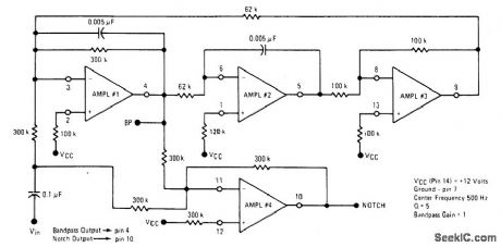
The Quad op amp MC4301 is used to configure a ftlter that will notch out a given frequency and produce that notched-out frequency at the BP terminal, useful in communications or measurement setups. By proper component selection any frequency ftlter up to a few tens of kilohertz can be obtained. (View)
View full Circuit Diagram | Comments | Reading(922)
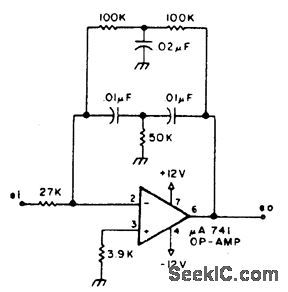
ACTIVE_BANDPASS_FILTER
Published:2009/7/2 3:16:00 Author:May
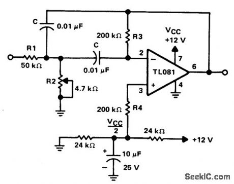
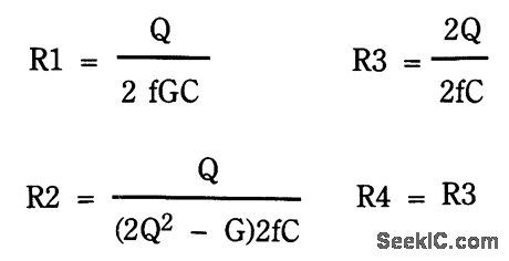
The circuit is a two-pole active filter using a TL081 op amp. This type of circuit is usable only for Qs less than 10. The component values for this filter are calculated front the following equations.The values shown are for a center frequencyof 800 Hz. (View)
View full Circuit Diagram | Comments | Reading(1592)
BANDPASS_FILTER
Published:2009/7/2 3:14:00 Author:May
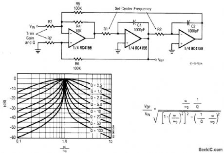
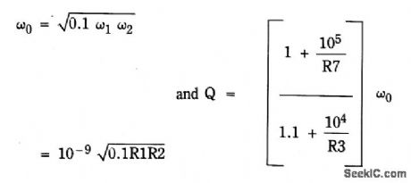
The input signal is applied through R3 to the inverting input of the summing amplifier and the output is taken from the first integrator. The summing amplifier will maintain equal voltage at the inverting and non-inverting inputs. Defining 1/R1C1 as ω1 and 1/R2C2 as ω2, this is now a convenient form to look at the center-frequency ω0 and ftlter Q.The frequency response for various values of Q is shown. (View)
View full Circuit Diagram | Comments | Reading(0)
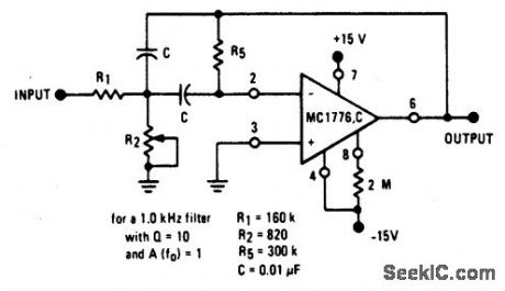
ACTIVE_BANDPASS_FILTER_f0_1000_Hz
Published:2009/7/2 3:10:00 Author:May
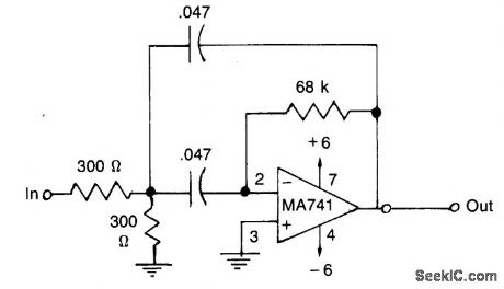
This filter has a bandpass centered around 1kHz, for applications such as bridge amplifiers, null detectors, etc.The circuit uses a μA741 IC and standard 5% tolerance components. (View)
View full Circuit Diagram | Comments | Reading(1460)
PINK_NOISE_FILTER
Published:2009/7/2 3:10:00 Author:May
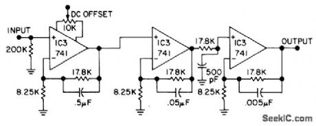
Used in acoustics for measuring transducer characteristics, absorption-reflection and transmission coefficients of materials, and room parameters such as reverberation time. Offsets falloff of detected noise signal at low frequencies by using filter shown to convert random-noise source from constant energy per hertz (white-noise frequency spectrum) to constant energy per octave (pink-noise response). Filter covers audio range from 10 Hz to 20 kHz, providing -20 dB per decade transmission characteristics with three 741 opamp stages. Frequency characteristic is independent of source and load impedances. Supply voltages can be from ±6 to ±18 V.-R. Mauro, Simple Pink Noise Filter. Audio. March 1977. p 36 and 38. (View)
View full Circuit Diagram | Comments | Reading(1347)
PRECISION,FAST_SETTLING,LOW_PASS_FILTER
Published:2009/7/2 3:02:00 Author:May
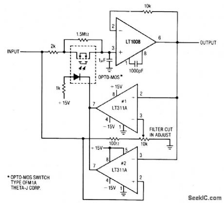
This circuit is useful where fast signal acquisition and high precision are required, as in electronic scales. The filter's time constant is set by the 2 K ohm resistor and the 1 μF capacitor until comparator No, 1 switches. The time constant is then set by the 1.5 M ohm resistor and the 1 μF capacitor. Comparator No. 2 provides a quick reset.The circuit settles to a final value three times as fast as a simple 1.5 M ohm-1μF filter, with almost no dc error. (View)
View full Circuit Diagram | Comments | Reading(800)
STATE_VARIABLE_FILTER
Published:2009/7/2 2:22:00 Author:May
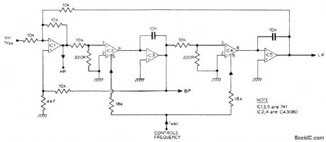
The filter produces three outputs: high-pass, bandpass, and low-pass. Frequency is linearly proportional to the gain of the two integrators. Two CA3080's, (IC2, 4) provide the variable gain, the resonant frequency being proportional to the current IABC. Using 741 op amps for IC3 a control range of 100 to 1, (resonant frequency) can be obtained.If CA3140's are used instead of 741's then this range can be extended to nearly 10,000 to 1. (View)
View full Circuit Diagram | Comments | Reading(1576)
RAZOR_SHARP_CW_FILTER
Published:2009/7/2 2:57:00 Author:May
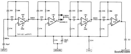
The circuit consists of four stages of active bandpass ftltering provided by two typeμA747 integrated-circuit dual op amps and includes a simple threshold detector (diodes D1 and D2) between stages 2 and 3 to reduce low-level background noise. Each of the four filter stages acts as a narrow bandpass ftlter with an audio bandpass centered at 750 Hz. The actual measured 3-dB bandwidth is only 80 Hz wide. (View)
View full Circuit Diagram | Comments | Reading(2078)
DIGITALLT_TUNED_LOW_POWER_ACTIVE_FILTER
Published:2009/7/2 2:53:00 Author:May
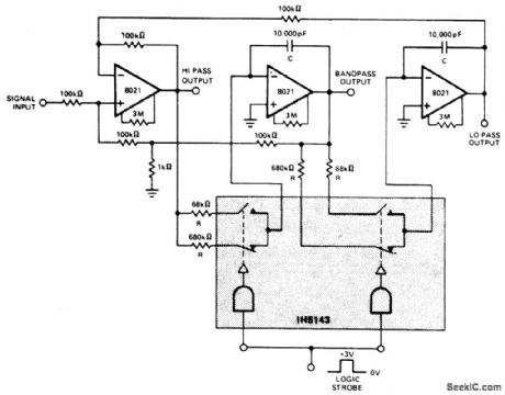
This constant gain, constant Q, variable frequency filter provides simultaneous low-pass, bandpass, and high-pass outputs with the component values shown, the center frequency will be 235 Hz and 23.5 Hz for high and low logic inputs respectively; Q = 100, and gain = 100. (View)
View full Circuit Diagram | Comments | Reading(860)
ACTIVE_LOW_PASS_FILTER_WITH_DIGITALLY_SELECTED_BREAK_FREQUENCY
Published:2009/7/2 2:50:00 Author:May
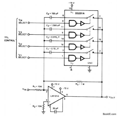
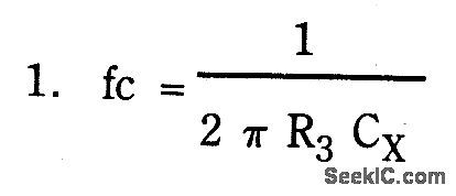
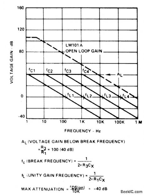
Variable low-pass ftlter has break frequencies at1, 10, 100 Hz and 1 kHz. The break frequency isThe low frequency gain isA second break frequency(a zero)is introduced by rDS(on )of the DG201A,causing theminimum gain to bea maximum attenuation of 40 dB (80 dB relative to the low frequency gain)。 (View)
View full Circuit Diagram | Comments | Reading(925)
WIDEBAND_TWO_POLE_HIGH_PASS_FILTER
Published:2009/7/2 2:26:00 Author:May

The circuit provides a 10MHz cutoff frequency.Resistor R3 ensures that the tnputcapacitance of the amplifier does not interact with the filter response at the frequencyof interest.An equivalent low pass filter is similarly obtained by capacitance and resistance transformation (View)
View full Circuit Diagram | Comments | Reading(0)
LOW_COST_UNIVERSAL_ACTIVE_FILTER
Published:2009/7/2 2:18:00 Author:May
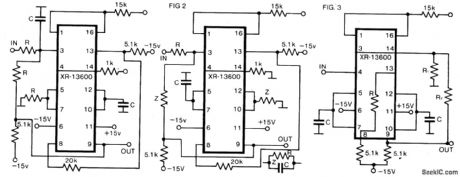
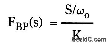
The circuit as shown in Fig. 1 gives the bandpass operation the transfer function calculated from
Interchanging the capacitor C with the resistor R at the input of the circuit high-pass operation is obtained. A low-pass filter is obtained by applying two parallel connections of R and C as shown in Fig. 2.
The low-pass operation may be much improvedwith the circuit as gtven h Fig.3.Here the gamand Q may be set up separately with respectto the cut-off frequency according to theequations (View)
View full Circuit Diagram | Comments | Reading(948)
VOLTAGE_CONTROLLED_FILTER
Published:2009/7/1 23:22:00 Author:May
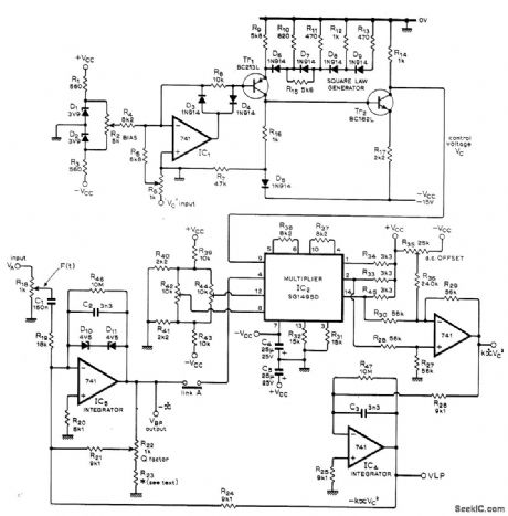
Used in elaborate sound synthesizer developed for generating wide variety of sounds. Serves as bandpass filter for which resonant frequency is Iinearly proportional to sum of input control voltages and a bias voltage. Can also be used as notch filter or as spectrum analyzer. Three-part articledescribes operation in detail and gives all other circuits of synthesizer. Supply voltages are 15 V.with polarity as indicated.-T. 0rr and D W. Thomas. Electronic sound Synthesizer、Wireless World. Part 2--Sept 1973.p 429-434(Part 1-Aug 1973.p366-372; Part 3-Oct.1973.p 485-490) (View)
View full Circuit Diagram | Comments | Reading(3324)
F_V_WITH_OUTPUT_FILTER_
Published:2009/7/1 23:01:00 Author:May
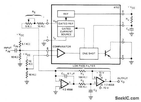
Two-pole low-pass active filter improves dynamic range and response time of Raytheon 4152 frequency-tovoltage converter. Ripple in output is less than 0.02 V P-P above 100 Hz. Requires ±15 V supply, Maximum inputfrequency is 10 kHzwhen CIN, is 0.002 μF, R0 is 6.8K, and C0 is 0.01μ F.- Linear Integrated Circuit Data Book, Raytheop Semiconductor Division, Mountain View, CA, 1978, p 7-48. (View)
View full Circuit Diagram | Comments | Reading(1093)
10_kHz_LOW_PASS_FILTER
Published:2009/7/1 21:13:00 Author:May
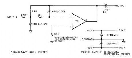
Suitable for use at both input and output of A/D-D/A converter in digital audio system for synthesizing speech or music. Serves for smoothing steps of output waveform and suppressing background noise on output when small signals are being processed with 8-bit Iinear encoding.-T. Scott. Digital Audio. Kilobaud, May 1977. p 82-86. (View)
View full Circuit Diagram | Comments | Reading(961)
SCRATCH_FILTER_USING_LM387
Published:2009/6/30 2:36:00 Author:May
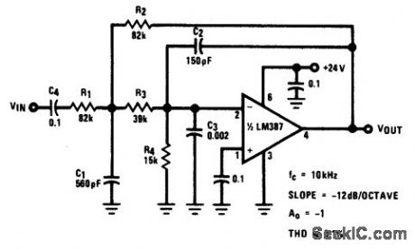
View full Circuit Diagram | Comments | Reading(710)
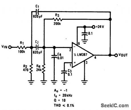
20_kHz_BANDPASS_ACTIVE_FILTER_
Published:2009/6/30 2:35:00 Author:May
View full Circuit Diagram | Comments | Reading(641)
RUMBLE_FILTER_USING_LM387
Published:2009/6/30 2:34:00 Author:May
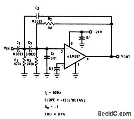
View full Circuit Diagram | Comments | Reading(754)
_MULTIPLE_FEEDBACK__BANDPASS_FILTER(10_kHz)
Published:2009/6/30 2:32:00 Author:May
View full Circuit Diagram | Comments | Reading(695)
160_Hz_BANDPASS_FILTER_
Published:2009/6/30 2:07:00 Author:May
View full Circuit Diagram | Comments | Reading(666)
| Pages:12/21 1234567891011121314151617181920Under 20 |
Circuit Categories
power supply circuit
Amplifier Circuit
Basic Circuit
LED and Light Circuit
Sensor Circuit
Signal Processing
Electrical Equipment Circuit
Control Circuit
Remote Control Circuit
A/D-D/A Converter Circuit
Audio Circuit
Measuring and Test Circuit
Communication Circuit
Computer-Related Circuit
555 Circuit
Automotive Circuit
Repairing Circuit