
Alarm Control
Index 4
General Purpose Alarm Circuit for Resistive Sensor
Published:2012/9/3 3:01:00 Author:Ecco | Keyword: General Purpose, Alarm Circuit , Resistive Sensor
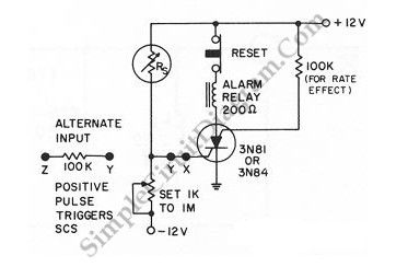

When the resistance value of a temperature, light, pressure, or any other resistive sensors Rs drops below a certain point (adjusted by a preset potentiometer), the SCR (silicon controlled switch) will be triggered. The sensor (Rs) and the potentiometer placement can be interchanged to get opposite action, where the SCR need to be triggered at the increase of sensing resistor (Rs). Here is the schematic diagram of the circuit: (Source: freecircuitdiagram)
(View)
View full Circuit Diagram | Comments | Reading(989)
Smoke alarm circuit composed of photoelectric smoke detection IC MC145010
Published:2012/8/26 22:48:00 Author:Ecco | Keyword: Smoke alarm , photoelectric, smoke detection IC

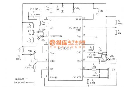
It uses 9V laminated battery. R2, C3 are respectively Oscillation resistor and oscillation capacitor, and the clock cycle is decided by following formula:
(View)
View full Circuit Diagram | Comments | Reading(1846)
Burglar alarm circuit composed of photodiode
Published:2012/8/19 22:36:00 Author:Ecco | Keyword: Burglar alarm , photodiode
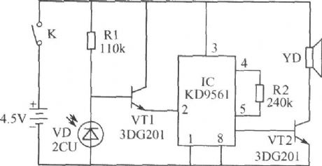
The alarm is mounted in a drawer. If the thief opens your drawer at night, the alarm will send the souud of ow - ow to warn thieves, and they will dare to start. Photosensitive diode VD, transistor VT1 and resistor R1 form a light control switch; integrated circuit IC, transistor VT2 and speaker YD form the alarm circuit. IC uses the KD-9561 four-tone analog alarm audio Manifold. VT1 and VT2 select 3DG201 silicon transistor with β value being greater than 60. VD selects 2CU photodiode. R1 and R2 use 1W carbon film resistors. YD uses 2.5 inches of electric speaker with impedance in 8Ω. Power select 3 and 5 battery. K selects small, self-resetting and normally closed contact button switch.
(View)
View full Circuit Diagram | Comments | Reading(2589)
Infrared burglar alarm circuit schematic
Published:2012/8/16 21:10:00 Author:Ecco | Keyword: Infrared , burglar alarm
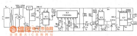
Infrared burglar alarm circuit schematic is shown in Figure 1. Infrared transmitter is a multivibrator with oscillation frequency being 40kHz, and it is composed of IC2 ( NE555 ), R1 , R2 and C3. VLS is the infrared emission probe which can be used to radiate 40kHz high-frequency externally to form the IR beam. VDL is the infrared receiver probe, and it forms infrared receiver, shaping and amplifying circuit with IC3 (CX20106A), and the infrared signal can be converted into electrical pulses after being amplified. IC4 and its peripheral components form alarm implementation circuit, once pin 2 is in low level, the circuit immediately flips, then the signal output end pin 3 is immediately converted to high level output, and it has delay function at the same time. Usually , VDL receives the infrared beam being radiating by VDL.
(View)
View full Circuit Diagram | Comments | Reading(2401)
The water height alarm circuit diagram
Published:2012/8/6 4:23:00 Author:Ecco | Keyword: water height , alarm
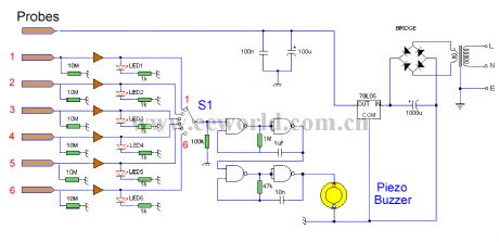
This circuit will trigger with any fluid with a resistance under 900K between the maximum separation distance of the probes. Let me explain further. The circuit uses a 4050B CMOS hex buffer working on a 5 volt supply. All gates are biased off by the 10M resistors connected between ground and buffer input. The common probe the topmost probe above probe 1 in the diagram above is connected to the positive 5 volt supply. If probe 1 is spaced 1 cm away from the common probe and tap water at 25 ?C is detected between the probes (a resistance of 20k) then the top gate is activated and the LED 1 will light. Similarly if probe 2 at 2 cm distance from the common probe detects water, LED 2 will light and so on. Switch 1 is used to select which output from the hex buffer will trigger the audible oscillator made from the gates of a CMOS 4011B IC.Placement of Probes:As 7 wires are needed for the probe I reccommend the use of 8 way computer ribbon cable. The first two wires may be doubled and act as the common probe wire. Each subsequent wire may be cut to required length, if required a couple of millimetres of insulation may be stripped back, though the open cut off wire end should be sufficient to act as the probe. The fluid and distance between probe 6 and the common probe wire must be less than 900k. This is because any voltage below 0.5 Volt is detected by the CMOS IC as logic 0. A quick potential check using a 900k resistance and the divider formed with the 10M resistor at the input proves this point: 5 x (0.9 / (0.9+10) = 0.41 Volt. (View)
View full Circuit Diagram | Comments | Reading(1842)
Gas - smoke alarm circuit with Triac
Published:2011/8/29 1:34:00 Author:Jessie | Keyword: Gas - smoke alarm , Triac
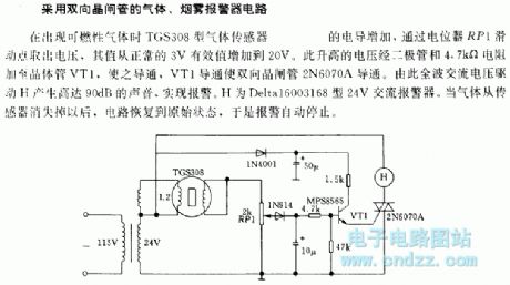
When it appears combustible gas, the conductanceof gas sensor TGS308will increase.The voltageon potentiometer RP1 sliding points increases from normal 3V to 20V. This increased voltage is added to the transistor VT1 and makes it turn on by the diode and 4.7Ω resistor, then the Triac 2N6070A is turned on. Full-wave AC voltage drives H to produce 90dB sound and alarm. H is 24V AC Delta16003168 alarm. When the gas disappears from the sensor, the circuit recovers to its original state, so the alarm automatically stops. (View)
View full Circuit Diagram | Comments | Reading(1777)
Rice seeding bed high temperature alarm circuit
Published:2011/12/5 1:08:00 Author:May | Keyword: Rice seeding bed, high temperature alarm
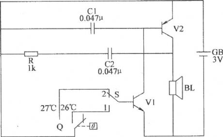
This rice seeding bed high temperature alarm circuit consists of electric hot thermometer Q, switch S, transistors V1, V2, resistor R, capacitors C1, C2, GB speaker BL and battery GB(V1, V2, and C1, C2, R, BL make up complementary oscillator circuit), and it isshown in the diagram. Component selection: R chooses 1/4W metal film resistor or carbon film resistor. C1 or C2choose polyester capacitors or monolithic capacitors. V1chooses 3DG6 or S9013 NPN silicon transistor; V2chooses 3AX81 germanium PNP transistors. BLchooses chose 0.25W, 812 electric loudspeaker. Qchooses fixed electric hot mercury thermometer. Schooses double-pole toggle switch. GBchooses two AA batteries. (View)
View full Circuit Diagram | Comments | Reading(1453)
Double-limit temperature alarm circuit 2
Published:2011/11/23 2:07:00 Author:May | Keyword: Double-limit, temperature alarm
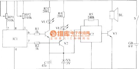
This double-limit temperature alarm circuit consists of temperature detection circuit control circuit, temperature indicating circuit and sound alarm circuit, as shown in the diagram.Component selection: R1 ~ R5 choose 1/4W carbon film resistor or metal film resistors. RP1 and RP2 chose small organic solid potentiometer. C choses electrolytic capacitors voltage is 10V. VL1 and VL2 are chose high-brightness light-emitting diodes φ3mm, VL1 is red, VL2 is green. VS chooses 1/2W, 3V voltage silicon diodes. V1 and V3 choose S9013 or C8050 silicon NPN transistor; V2 chooses S9015 or C8550 silicon PNP transistors. IC1 chooses TC602 temperature sensor integrated circuit; IC2 chooses S9015 or C8550 type silicon PNP transistor.BL chooses 0.25W, 8Ω micro-electric speaker. S chooses small single pole toggle switch. GB chopses 6V battery stack. (View)
View full Circuit Diagram | Comments | Reading(1295)
Miner lamp battery alarm circuit diagram
Published:2011/11/9 21:49:00 Author:May | Keyword: Miner lamp battery alarm

This circuit uses the miners lamp battery as its power source, and it isinstalled in ore cap, when gas is over, the head lamp buld will automatically flash, and itis accompanied by alarm sound.
This circuit uses less component, and ithas no influenceon miner's normal work,it costs low with adjustable emergency alarm, and it is easy to carry.
(View)
View full Circuit Diagram | Comments | Reading(978)
Four-sound circulating burglar alarm circuit
Published:2011/10/27 21:52:00 Author:May | Keyword: Four-sound circulating, burglar alarm
When field-effect tube VT1 (3DJ6)'s wire is serviceable, it presents cut-off state, andpin 2 of JG (555) setting trigger end presents high level, and 555 is in reset state, namely pin 3 presents low level ( it islower than 0.4V). 555 and R1, C1 form the monostable trigger circuit. Whenpeople touch wire, human body's induction signal is amplified byVT1,set byIC1, thenits pin 3 turns to high level ( about 6V) to offer work voltage to IC2, VT2, etc.
When the wire is broken, IC1 is always in setting state, IC2, IC6, etc get electricity to be in continuous alarm state, and it send sout four- sound circulating alarm sound. IC2 and R2, R3, C4, etc make up ultra-low frequency multivibrator, and the oscillation or not depends on thepower supply. Its oscillation frequency f=1.44/(R2+2R3)C4. (View)
View full Circuit Diagram | Comments | Reading(1015)
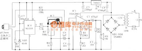
Wireless motorcycle burglar alarm circuit
Published:2011/10/24 2:32:00 Author:May | Keyword: Wireless, motorcycle burglar alarm
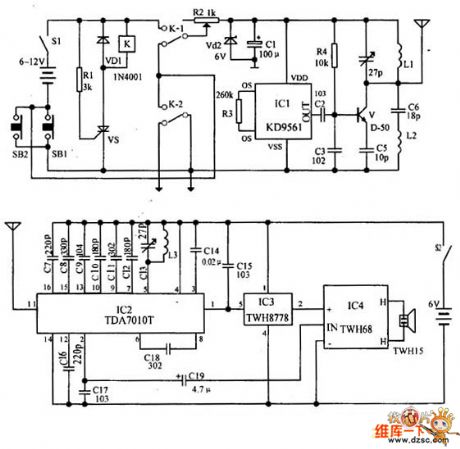
The relay K and SCR VS are used to control the transmitter circuit's power. IC1 forms the alarm signal circuit. And the transistor V and its peripheral components form the radio frequency oscillator circuit to transmit alarm signal. In the waiting state, the switch S1 is connected, and SB1 is disconnected (ie, the front lock is locked), K is in the release state, then the alarm transmitter does not work. When the lock is opened (ie SB1 is connected), VS is triggered for conduction, K is pulled in to turn on the transmitter power. SB1 is switched on, K-2's normally open point is self-locking, and only alarm S1 disconnecting can end the alarm at this time. When K acts, its normally closed contact K-l is off.
(View)
View full Circuit Diagram | Comments | Reading(1496)
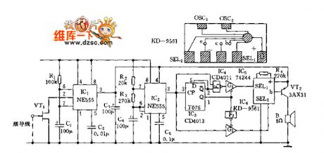
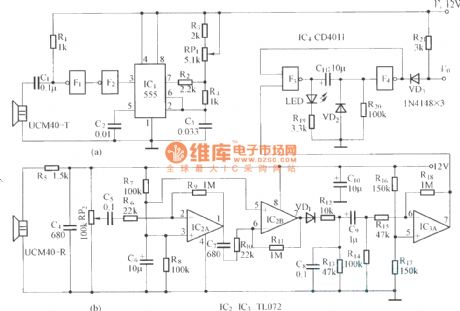
Ultrasonic guard against theft alarm detector
Published:2011/9/15 2:21:00 Author:Rebekka | Keyword: Ultrasonic guard against theft alarm
View full Circuit Diagram | Comments | Reading(1922)
Multi-tone alarm
Published:2011/11/11 2:56:00 Author:Ecco | Keyword: Multi-tone alarm
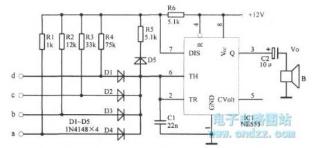
View full Circuit Diagram | Comments | Reading(1111)
Electric flute alarm circuit
Published:2011/11/8 21:10:00 Author:Ecco | Keyword: Electric flute alarm, 555
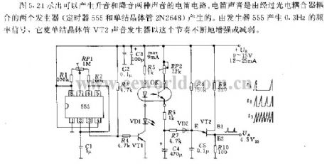
Figure 5.21 shows the tone circuit circuit which can produce two voices with rising tone and dropping tone. Electric flute sound is generated by two generators coupled by optical coupler ( single-junction transistor 2N2648 and the timer 555). 555 generates 0.3HZ frequency signal which makes single-junction transistor VT2 keep this sound increasing or decreasing according to the section.
(View)
View full Circuit Diagram | Comments | Reading(1547)
120db sweepfrequency alarm circuit
Published:2011/11/3 2:46:00 Author:Ecco | Keyword: 120db , sweepfrequency alarm

View full Circuit Diagram | Comments | Reading(1265)
Pyroelectric infared detection wireless alarm circuit diagram
Published:2011/9/26 22:02:00 Author:Rebekka | Keyword: Pyroelectric infared detection , wireless alarm
View full Circuit Diagram | Comments | Reading(907)
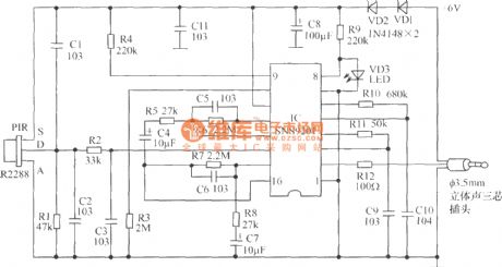
Human infrared thermal release alarm
Published:2011/9/26 22:01:00 Author:Rebekka | Keyword: Human infrared, thermal release alarm

Human infrared thermal release alarm can receive the heat releasing infrared ray issued by the body during the day or night, then it willgive the sound and light alarm. It is ideal for electronic guard. Working principle: The circuit uses imported IC, general-purpose sensor control circuit, high input impedance operational amplifier, it consists of the timer, the timer latch, and the operating voltage is 3.5V ~ 5V, and quiescent currentis 60μA. It uses 3 ~ 4 1.5V batteries or 6V ~ 12V rectifier. Pyroelectric infrared sensor RIP09 TL receives body heat release signal. The signal will be amplified by the first stage op amp in IC. Then it will be amplified and coupled by the second level of C6 amplifier. Then it will be sent to built-in comparator to have bidirectional amplitude discrimination. R2, C2 are delay control. If you need longer hours of work, you can increase the R2's resistance or the capacitance value ofC2, the circuit is set to 3s ~ 4s.
(View)
View full Circuit Diagram | Comments | Reading(2400)
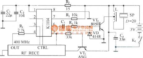
Electronic dog alarm circuit diagram
Published:2011/9/27 21:03:00 Author:Rebekka | Keyword: Electronic dog alarm
(1)Thepartschematic of infrared sensor electronic dog alarm probe.
Electronic dog alarm is composed of pyroelectric infrared sensor and alarm control speaker.
Alarm controlling speaker's principle diagram. (View)
View full Circuit Diagram | Comments | Reading(1573)
Detection alarm circuit diagram composed of TWH9248/TWH9249
Published:2011/10/18 1:12:00 Author:Rebekka | Keyword: Detection alarm circuit
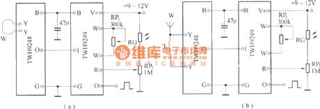
TWH9248/TWH9249 is a pair of microwave sensing components (also known as radar detectors). It is mainly used for movement detection of human body or object. The effective detection distance is 3-6 meters, voltage is 9-12V.
(View)
View full Circuit Diagram | Comments | Reading(1169)
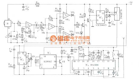
Wireless track warning module with wide frequency rolling code ( KB318/KB318R )
Published:2011/10/19 22:45:00 Author:Rebekka | Keyword: Wireless track , warning module , wide frequency, rolling code

Remote control transmitter schematic.
Micro receiver circuit.
The circuitsare used for automobiles, motorcycles and other alarm feedback occasions that needs long-distance wireless BP machine-style. It adopts advanced technologies and devices with improved functionality. It is better than other similar products.It iscomposed of a wireless transmitter KB318T (or KB923T) and a key ring type micro receiver alarm KB318R (or KB923R).
(View)
View full Circuit Diagram | Comments | Reading(865)
| Pages:4/18 123456789101112131415161718 |
Circuit Categories
power supply circuit
Amplifier Circuit
Basic Circuit
LED and Light Circuit
Sensor Circuit
Signal Processing
Electrical Equipment Circuit
Control Circuit
Remote Control Circuit
A/D-D/A Converter Circuit
Audio Circuit
Measuring and Test Circuit
Communication Circuit
Computer-Related Circuit
555 Circuit
Automotive Circuit
Repairing Circuit