
Alarm Control
Index 16
consisting of TWH8751 lock control anti-theft alarm circuit
Published:2011/7/8 3:20:00 Author:Fiona | Keyword: lock control anti-theft alarm
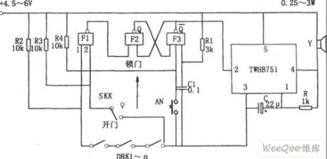
Figure shows the lock control anti-theft alarm circuit. The circuit consists of RS flip-flop, gated oscillator, the alarm circuit and so on.RS flip-flop consists of the NAND gate F2, F3, strobe oscillator consists of integrated circuits TWH8751 and R, C.
When the SKK is in the lock position, and the input 2 of NAND gate F1 is high, the state of DBK1-n is direct reflected by F1, if DBK1-n has an open circuit, the F1 output is low, RS flip-flop is set to 1 ,Choose the end (2) feet of the corresponding TWH8751 is low, trigger oscillator starts to oscillate, the oscillation signal makes the loudspeaker alarm.
(View)
View full Circuit Diagram | Comments | Reading(873)
Engine Water Supply Alarm Four
Published:2011/7/7 7:34:00 Author:Felicity | Keyword: Engine Water Supply Alarm
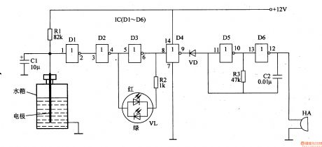
When the water level of the tank is above the lowest water level, electrode is connected to ground (the iron) through the resistance of water. And the input voltage of D1 is low; the output voltage of D2 is low and the output voltage of D3 is high. The green LED inside VL is on. And the output voltage of D4 is low; VD is on; the audio oscillator consists of D5, D6, R3 and C2 doesn’t work, HA is noiseless.When the water level is the same as the lowest water level (i.e. the electrode is just above the water), the output of D3 is at high level and the green LED inside VL is on while the green on is off. And the output of D4 is at high level to make VD cut off and then the audio oscillator works, then HA send out beeps.
(View)
View full Circuit Diagram | Comments | Reading(792)
Engine Water Supply Alarm Two
Published:2011/7/7 3:21:00 Author:Felicity | Keyword: Engine Water Supply Alarm
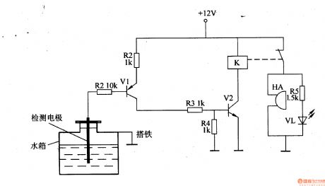
While the water level of the tank is higher than the lowest water level, the water level detect electrode is connected to ground through the resistance of water. V1 is on because of low level voltage of the base, and the high level voltage output by collector is divide by R3 ,R4 and then connect to the base of V2 to make V2 saturated and on and then K is on and the normally off contact of K is off ,then HA is noiseless and VL is off.While the water level in the tank is lower than the lowest water level , the water level detect electrode is above water to make V1 and V2 cut off, and K releases, HA is on and send out alarm, HL is on to warn the driver that the water level of tank is too low and should refill it
(View)
View full Circuit Diagram | Comments | Reading(1768)
Engine Water Supply Alarm One
Published:2011/7/7 3:07:00 Author:Felicity | Keyword: Engine Water Supply Alarm
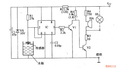
While the engine is not short of water, the electrode of the sensor is connected to ground (the iron) to make the voltage of pin 2 and pin 6 at low level (lower than Vcc/3). The output of pin 3 is at high level to make V1 on, and V2 cut off, then HA is noiseless and HL is off. While the water level of the engine is below the electrode of the sensor, the voltage of pin 2 and pin 6 are at high level (higher than 2Vcc/3). The circuit of IC changes and pin 3 outputs low voltage to make V1 cut off ,and V2 on, and then HA send out beeps and HL is also on to warn the driver the engine is short of water.
(View)
View full Circuit Diagram | Comments | Reading(923)
Agricultural submersible pump burglar alarm circuit diagram
Published:2011/6/12 22:55:00 Author:Lucas | Keyword: agricultural , submersible pump, burglar alarm
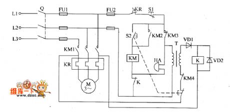
The agricultural submersible pump burglar alarm circuit is composed of the relay K, diodes VD1, VD2, power transformer T and bell HA, and the circuit is shown as the chart. When the submersible pump is stolen or disconnected because of other reasons, the power supply loop of relay K is cut off, and the normally closed contact is connected, then HA produces alarm sound. VD1 and VD2 use 1N5402 silicon rectifier diode or 2CP35B ordinary silicon diodes. HA chooses the alarm bell with working voltage being 380V. K selects JQX-4 24V DC relay. KM uses CDC10 380V AC contactor. T uses the power transformer with 3 ~ 5W, 25 ~ 30V secondary voltage(380V/25 ~ 30V). S1 selects moving off button; S2 selects portfolio button (each grous of moving on, moving off contacts). Fuse FU1, knife switch Q and the thermal relay KR should be selected according to the rated power of M; FU2 uses 2A fuse.
(View)
View full Circuit Diagram | Comments | Reading(2768)
Telephone line burglar alarm circuit diagram
Published:2011/6/30 5:36:00 Author:Lucas | Keyword: Telephone line, burglar alarm
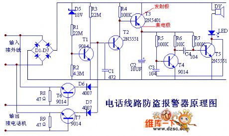
The breakover of T2 makes T3 breakover, and then the rear audio oscillation circuit, and LED, DY will emit aural and visual alarm, and it can add the interfere signal on out wire by LED, DY , while the voltage of out wire decreases, so those theft callers are forced to hang up as they can not dial. This alarm can monitor and prevent others from unauthorized using of your telephone line. When someone outside connects to your phone line and makes a free call, the alarm will issue the interference signals to forbid thieves from dialing, then it uses sound and light to inform of the owner somone having used the call.
(View)
View full Circuit Diagram | Comments | Reading(1393)
The gas limiting alarm miner lamp circuit diagram 4
Published:2011/7/4 22:05:00 Author:Lucas | Keyword: Gas limiting , alarm , miners lamp
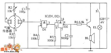
The gas limiting alarm miner lamp circuit is composed of the gas detection circuit, multivibrator, audio output circuit and the lighting circuit, and the circuit is shown as the chart. Gas detection circuit is composed of the gas sensor and resistors R2, R3. Multivibrator is composed of the two NAND gates D1, D2 which are inside of the NOT gate IC and resistors R4 and R5, capacitor C2. Audio output circuit consists of resistor R6, audio amplification tube V and speaker BL. Lighting circuit is composed of the battery GB, illuminating lamp EL and light switch S. R1 uses 1/2W carbon film resistor; R2 uses small sealed variable resistor; R3 ~ R6 select 1/4W carbon film resistors.
(View)
View full Circuit Diagram | Comments | Reading(833)
Non-contact sensor alarm circuit
Published:2011/6/24 10:54:00 Author:Fiona | Keyword: Non-contact, sensor alarm

G is representative of sensors in the picture,there is a distributed capacitance Co existing between G and ground, capacitance three-point oscillator composed of Co and L, C1, V1,in the return circuit composed of Co, C1, L,in the view of alternating current path,C0 and C1 are connected in series. When no one is close to G,Co is small,when it connected in series with C1, both ends of the partial pressure of Co is greater than both ends of the partial pressure of C1,the both ends high frequency voltage of Co is fed to V1 base through C3,it's enough to keep three-point oscillator to produce oscillation.
(View)
View full Circuit Diagram | Comments | Reading(1014)
Gas leak alarm circuit diagram
Published:2011/6/13 5:04:00 Author:Lucas | Keyword: Gas leak alarm
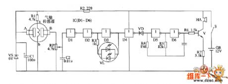
The gas leak alarm circuit is composed of the power supply circuit, gas detection circuit, LED indicating circuit and sound alarm circuit, and the circuit is shown as the chart. Power supply circuit is composed of the battery CB, power switch s, current limiting resistor R2, zener diode VS and filter capacitor C1. Gas detection circuit consists of the gas sensor, resistors R1 and potentiometer RP. LED indicating circuit consists of the NOT gates D1~D2 which are inside of NOT gate integrated circuit IC1(D1~D6), resistor R3, capacitor C2, and two-color light-emitting diodes VL. Sound alarm circuit is composed of the diode VD, NOT gates D4~D6 which are inside of IC, resistors R4 ~ R7, capacitor C3, transistor V, and buzzer HA. R2 uses 1/2W metal film resistor.
(View)
View full Circuit Diagram | Comments | Reading(1627)
Intelligent lock control balcony alarm bell circuit diagram
Published:2011/6/20 6:36:00 Author:Lucas | Keyword: Intelligent, lock control , balcony , alarm bell
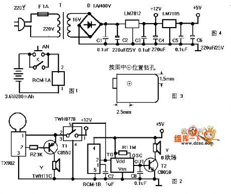
Figure 1 is a transmitter circuit which is installed at the gate. AN is the doorbell button, and K is the lock control switch; when all the family goes out and locks the check-lock for insurance, the K connected automatically to play the role of fortification. When people press the AN or connect K, RCM-1A will launch 250 ~ 300MHz radio wave by modulation, Figure 2 is a receiver circuit, which is installed in the balcony ceiling, and RCM-1B can receive the modulation radio waves and pin 2 output is in high level, thereby it triggers the language IC to work.
(View)
View full Circuit Diagram | Comments | Reading(1211)
Gas / smoke alarm circuit diagram
Published:2011/6/14 3:29:00 Author:Lucas | Keyword: Gas, smoke , alarm
The gas / smoke alarm circuit is shown in Figure, and it is composed of the power supply circuit, sensor and multivibrator. One way of the 220V mains electricity bucked by the transformer, rectified by full bridge, filtered by capacitor and through the three-terminal voltage regulator can provide +S V voltage for the gas sensor, the other way can directly supply multivibrator speaker. Sensor uses QM-N 5 or QM 211 type. It is a relatively strong universal gas sensor which is suitable for the smoke and fire caused by natural gas, coal gas, LPG, gasoline, carbon monoxide, hydrogen, alkanes, alcohols, and wood, paper; cloth, hair products, rubber products, plastic products and oil and so on.
(View)
View full Circuit Diagram | Comments | Reading(956)
Agricultural irrigation line burglar alarm circuit diagram 2
Published:2011/6/16 3:47:00 Author:Lucas | Keyword: Agricultural, irrigation line , burglar alarm
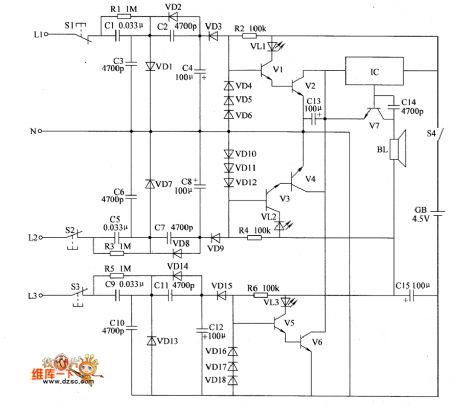
The agricultural irrigation line burglar alarm circuit is composed of the detection circuit, LED indicator circuit and sound alarm circuit, and the circuit is shown as the chart. Detection circuit is composed of the test buttons S1 ~ S3, resistors RI ~ R3, capacitors C1 ~ C12 and diodes VD1 ~ VD3, VD7, VD9, VD13 ~ VD15. LED indicator circuit consists of resistors R4 ~ R6, light-emitting diodes VL1 ~ VL3, transistors VI ~ V6 and diodes VD4 ~ VD6, VD10 ~ VD12, VD16 ~ VD18. Sound alarm circuit is composed of the audio integrated circuit IC, capacitors C5 ~ C7, transistor V7 and speaker BL. R1, R3 and R5 select 1/2W metal film resistors.
(View)
View full Circuit Diagram | Comments | Reading(924)
Inductive anti-theft alarm circuit diagram
Published:2011/6/14 5:06:00 Author:Lucas | Keyword: Inductive, anti-theft alarm
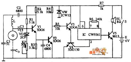
The circuit is shown as the chart. The voltage on R3 is higher to stop the multiple valve composed of V4 and V2 and conduct V2, and it cuts off the four tones analog integrated circuit, and the speaker does not sound. When someone closes to the sensor, the value of C0 increases and the high-frequency differential pressure decreases. The voltage sent to the base of V1 by C3 can not maintain the oscillation of V1 and V1 stops vibration immediately. At this point the voltage on R3 becomes smaller, and V2 stops, then V3, V4 conduct and the pin ② of IC gets power and works.Pin ③ emits siren signal which is amplified by the V5 and output from the loudspeaker, and it will emit warning sound.
(View)
View full Circuit Diagram | Comments | Reading(1247)
The sound and light alarm circuit diagram 1 for industrial instrumentation
Published:2011/6/9 4:40:00 Author:Lucas | Keyword: sound , light, alarm, industrial instrumentation
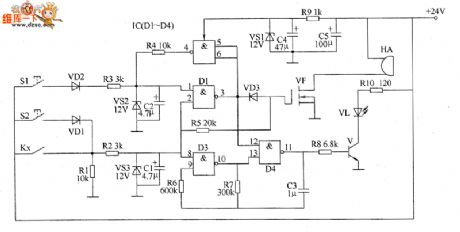
The sound and light alarm circuit for industrial instrumentation is composed of the detection control circuit, bistable trigger, LED flash circuit, sound alarm circuit and +12 V voltage regulator circuit, and the circuit is shown as the chart. Detection control circuit is composed of controlled contact of industrial instrument (controlled electric contact) Kx, resistors R1, R2, zener diode VS3 and capacitors C1. LED flash circuit consists of the D3, D4 which are inside of NAND gate integrated circuit IC (D1 ~ D4), resistors R6 ~ R8, R10, capacitor C3, transistor V and LED VL. Sound the alarm circuit is composed of resistor R5, field-effect transistor VF and alarm HA. R1 ~ R8 select l/4W metal film resistors.
(View)
View full Circuit Diagram | Comments | Reading(1261)
Hazardous area alarm circuit diagram 3
Published:2011/6/2 3:57:00 Author:Lucas | Keyword: Hazardous area , alarm
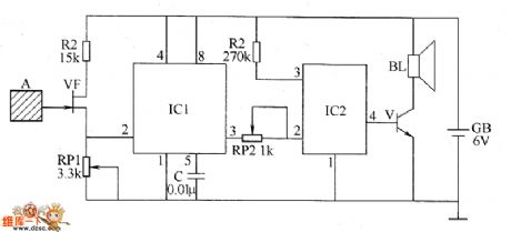
The hazardous area alarm circuit is composed of the induction electrode piece A, JFET VP, time-base integrated circuit ICl, language integrated circuit IC2, audio amplifier tube V and speaker BL, and the circuit is shown as the chart. Adjusting the resistance of RP1 and RP2 can change the sensitivity of the circuit, so if people were less than 0.5m from the induction electrode piece, the alarm will emit sound. If people were 0.5m far away from the induction electrode piece, the alarm does not emit sound. R1 and R2 select 1/4W carbon film resistors. RP1 and RP2 use sealed variable resistors. C uses polyester capacitor or monolithic capacitor. V uses 59013 silicon NPN transistor. VF uses 3DJ6 field effect transistor. BL uses 0.5W, 8Ω electric speaker.
(View)
View full Circuit Diagram | Comments | Reading(967)
Hazardous area alarm circuit diagram 2
Published:2011/6/2 3:49:00 Author:Lucas | Keyword: Hazardous area, alarm
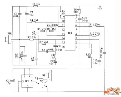
The hazardous area alarm circuit is composed of the pyroelectric infrared sensor (PIR), signal processing circuit and the language remind circuit, and the circuit is shown as the chart. Signal processing circuit is composed of the pyroelectric infrared signal processing integrated circuit IC1 and resistors R4 ~ R12, capacitors C4 ~ C12. The language remind circuit is composed of the speech integrated circuit IC2, transistors V1 and V2, resistor R13, capacitor C13 and speaker BL. R1 ~ R13 use 1/4W carbon film resistors. C1, C2, C4, C6 and C8 ~ C12 use polyester capacitors or monolithic capacitors; C3, C5, CT, C13 select aluminum electrolytic capacitors with the voltage in 10V. V1 selects 59013 NPN silicon transistor; V2 uses 58050 silicon NPN transistor. BL uses 0.25 ~ 0.5W, 8Ω electric speaker.
(View)
View full Circuit Diagram | Comments | Reading(1866)
Hazardous area alarm circuit diagram 1
Published:2011/6/2 3:44:00 Author:Lucas | Keyword: Hazardous area , alarm
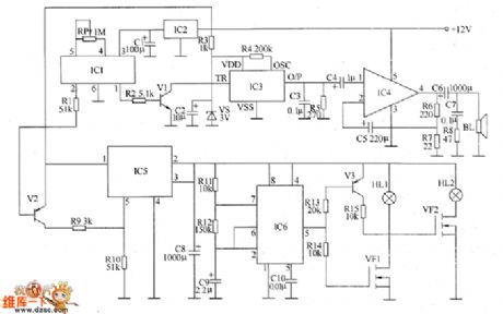
The voltage-stabilizing circuit is composed of three-terminal voltage regulator integrated circuit IC2, resistor R3, zener diode VS and filter capacitors C1, C2. Pyroelectric infrared detecting trigger circuit is composed of the pyroelectric infrared detection module IC1, transistors V1, V2, resistors R1, R2 and potentiometer RP. Electronic switch circuit consists of the electronic switch IC IC5, resistors R9, R10 and capacitor C8. Audio power amplifier consists of the power amplifier integrated circuit IC4, resistors R6 ~ R8, capacitors C4 ~ C7 and speaker BL. Low-frequency oscillator circuit consists of the time-base integrated circuit IC6, resistors R11, R12 and capacitors C9, C10 and other components.
(View)
View full Circuit Diagram | Comments | Reading(768)
Motorcycle burglar alarm circuit diagram
Published:2011/5/17 19:41:00 Author: | Keyword: Motorcycle, burglar alarm
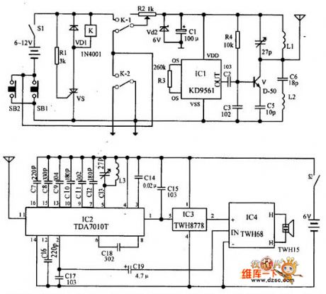
Transmitter: the relay K and SCR VS are used to control the power of transmitter circuit. IC1 forms alarm sound signal circuit. The transistor V and its peripheral components form RF oscillator circuit to transmit the alarm signal. When the circuit is in the waiting state, the switch S1 is connected, and SB1 is disconnected(the front lock is locked), K is in the release state, the alarm transmitter does not work. When the front lock is opened (SB1 is connected), VS is triggered and turned on, K pulls in, the transmitter gets power. When SB1 is switched on, the normal open point of K-2 will be self-locking, at this time, the S1 being disconnected can stop the alarm.
(View)
View full Circuit Diagram | Comments | Reading(2386)
Home Gas Safety Alarm Device Principle Circuit
Published:2011/5/16 9:29:00 Author:Robert | Keyword: Home, Gas, Safety, Alarm Device
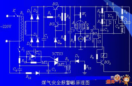
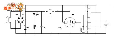
One part is the gas alarm device which would alarm before the gas density getting to the limit. The other part is a open negative ion generator whose function is generating air negative ion automatically. So the harmful ingredients carbon monoxide of the gas can react to the ozone (O3) in the air negative ion and this process produces harmless carbon dioxide.
The Home Gas Safety Alarm Device Principle Circuit is shown below.
(View)
View full Circuit Diagram | Comments | Reading(1287)
Over-temperature monitoring warning circuit diagram
Published:2011/5/12 1:23:00 Author:Rebekka | Keyword: Over-temperature monitoring warning
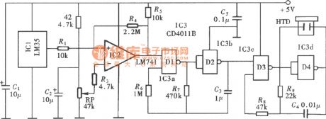
Over-temperature monitoring warning(LM35、LM741) circuit diagram is shown as above.
The over-temperature monitoring alarm circuit uses the integrated circuit temperature sensor as temperature measurement device. It only sets a maximum limiting temperature control points. When the temperature exceeds the limit temperature, the alert sounds, prompting the user to pay attention. The parts of the circuit is shown in the figure. It is composed of the temperature detector, over-temperature monitoring circuit, warning sound occurs and the output circuit. (View)
View full Circuit Diagram | Comments | Reading(1612)
| Pages:16/18 123456789101112131415161718 |
Circuit Categories
power supply circuit
Amplifier Circuit
Basic Circuit
LED and Light Circuit
Sensor Circuit
Signal Processing
Electrical Equipment Circuit
Control Circuit
Remote Control Circuit
A/D-D/A Converter Circuit
Audio Circuit
Measuring and Test Circuit
Communication Circuit
Computer-Related Circuit
555 Circuit
Automotive Circuit
Repairing Circuit