
Alarm Control
Index 3
Timer with alarm circuit
Published:2012/9/20 20:52:00 Author:Ecco | Keyword: Timer , alarm
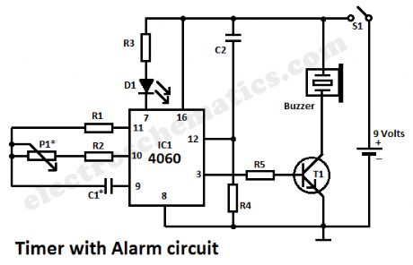
This simple alarm timer circuit is made with 4060 which has an integrated oscillator with a good stability with a relatively wide frequency range. In the circuit diagram the oscillator frequency is set by the RC network that is connected at pins 9, 10 and 11.When the timer with alarm circuit is connected with S1, the pulse from R4 and C2 common point will reset the counter and will start the counting. When it reaches 14 bit, the 13 pin passes in state H and the auto oscillating buzzer is powered by the control transistor T1.
The time interval is adjusted with P1. In order to get intervals ranging from one minute to two hours we should do a proper sizing of the oscillator components:
1 to 30 minutes: C1=220nF; P1=500KΩ
1 to 60 minutes: C1=470nf; P1=500KΩ
1 to 120 minutes: C1=470nF; P1=1MΩ
The power supply of the timer alarm is from a 9V battery. D1 led does not does not affect the operation of the circuit and was included only to show that it works. So, R3 and D1 are optional components.
S1 can be a tilt-sensitive switch with mercury if that will be used as a kitchen clock. With the buzzer on the power consumption of the timer alarm will be around 10 mA.
Timer Alarm circuit diagram
Components valuesP1 = 500kΩ (* read the list above)R1 = 2.2MΩR2 = 18kΩR3 = R5 = 1kΩR4 = 1MΩC1 = 220nF (* read the list above)C2 = 10nFT1 = BC547IC1 = 4060?
4 Responses to “Timer with alarm circuit”
Source: electroschematics.com
(View)
View full Circuit Diagram | Comments | Reading(1603)
Warning Alarm circuit with CD4001
Published:2012/9/19 21:49:00 Author:Ecco | Keyword: Warning Alarm

Unorthodox warning alarm circuit presented here is infact a single chip based general purpose sounder, which produces a pulsed alert tone when its input receives a valid trigger signal. The circuit can be easily interfaced with a number of electronic gadgets and sensors and it requires only 12V dc supply input for proper working. A positive level input at trigger point (J1) activates the warning alarm unit.At the heart of the circuit is a popular quad – two input NOR gate IC CD4001, here wired as two independent gated astable multivibrators. Initially, in standby mode, T1 is off and the tone generators are inactive. When T1 is enabled by a proper +ve level trigger signal, pin 1 of CD4001 is pulled low through switching diode D1 first astable block enters in active mode and then activates the second astable block, which is configured as an acoustic alarm. A large piezo-ceramic element (acoustic transducer) at the output of (pin 11) CD4001 will give superb results.
Warning Alarm Circuit Schematic
?
3 Responses to “Warning Alarm circuit with CD4001”
Source: electroschematic.com
(View)
View full Circuit Diagram | Comments | Reading(1380)
Step Alarm Circuit
Published:2012/9/19 21:41:00 Author:Ecco | Keyword: Step Alarm
This Circuit can monitor the door steps or Staircase. When a person crosses the steps, the alarm sounds indicating the entry. The circuit is too sensitive and operates in day light.The circuit uses an NPN Darlington phototransistor L14F1. It senses the intensity of light through its exposed base and passes current in the collector- emitter path. When there is light, the phototransistor conducts and C1 charges up to its full voltage level. The alarm circuit uses a Monostable timer built around IC NE555. The triggering threshold of IC1 is adjusted using VR1. So normally the trigger pin 2 of IC1 remains high as set by VR1. When the shadow of the moving person masks the phototransistor, it turns off allowing C1 to discharge through R1. This momentarily makes the trigger pin 2 of IC1 low and the timing cycle starts. With the given values of R2 and C2, Buzzer sounds for two minutes.
Step Alarm Circuit
SettingThe circuit can be constructed on a small piece of Perf board. The circuit is designed to operate in day light. Switch off the circuit in the evening to avoid false alarm. If a lamp is provided opposite to the phototransistor on the opposite wall of staircase, the circuit can be used as day and night alarm. Align the lamp in the line – of – sight of Phototransistor. Adjust VR1 till the circuit becomes silent.?
8 Responses to “Step Alarm Circuit”
Source: electroschematic.com
(View)
View full Circuit Diagram | Comments | Reading(877)
Tiny Door Guard with Alarm
Published:2012/9/19 21:23:00 Author:Ecco | Keyword: Tiny Door Guard , Alarm
This simple Door Chime protects the door and gives a loud Alarm tone when there is an attempt of theft. The circuit is too simple and battery operated.
A Normally Closed (NC) reed switch and magnet is used to trigger the circuit. Alarm generator is the popular ROM IC UM 3561. This 8 pin IC has an inbuilt oscillator to generate 4 siren tones like, Ambulance siren, Police siren, Fire brigade siren and Gun sound. The different tones can be selected using its pin 6 connected to VCC, Ground or not connected. Frequency of oscillation is determined by the 220K resistor connected to the pins 7 and 8 of the IC.UM 3561 is the low power IC and its maximum voltage rating is 3 volts. So Zener diode ZD is used to give 3 volts supply to IC. Medium power NPN transistor T1 amplifies the output pulses from IC1 to a loud siren.
Tiny Door Guard Circuit
Magnet can be a small sized one that is to be fixed in the door using double sided adhesive tape. Fix the circuit board in the door frame. Fix Reed switch in the door frame, very close to the door. So that, when the door is closed, the magnet will pull the contacts of the reed switch to break supply to the IC. When the door opens, contacts of the reed switch make contact and IC gets power to give alarm.?
15 Responses to “Tiny Door Guard with Alarm”
Source: electroschematic.com
(View)
View full Circuit Diagram | Comments | Reading(880)
Anti-bag-snatching alarm circuit
Published:2012/9/16 20:34:00 Author:Ecco | Keyword: Anti-bag-snatching, alarm
This circuit, enclosed in a small plastic box, can be placed into a bag or handbag. A small magnet is placed close to the reed switch and connected to the hand or the clothes of the person carrying the bag by means of a tiny cord. If the bag is snatched abruptly, the magnet looses its contact with the reed switch, SW1 opens, the circuit starts oscillating and the loudspeaker emits a loud alarm sound. (View)
View full Circuit Diagram | Comments | Reading(1179)
IR Motion Detector alarm
Published:2012/9/13 21:22:00 Author:Ecco | Keyword: IR Motion Detector , alarm
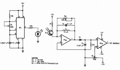
This type of motion detector uses the same basic concept as the active infrared motion detector. An interruption in a 5 kHz modulated pulsating beam that is transmitted by an infrared diode and received by an infrared transistor sets off the alarm.
Source: NEXT.GR (View)
View full Circuit Diagram | Comments | Reading(1762)
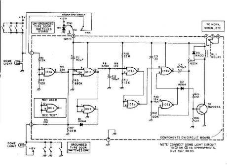
Auto-Arming Car Alarm circuit
Published:2012/9/11 21:32:00 Author:Ecco | Keyword: Auto-Arming, Car Alarm
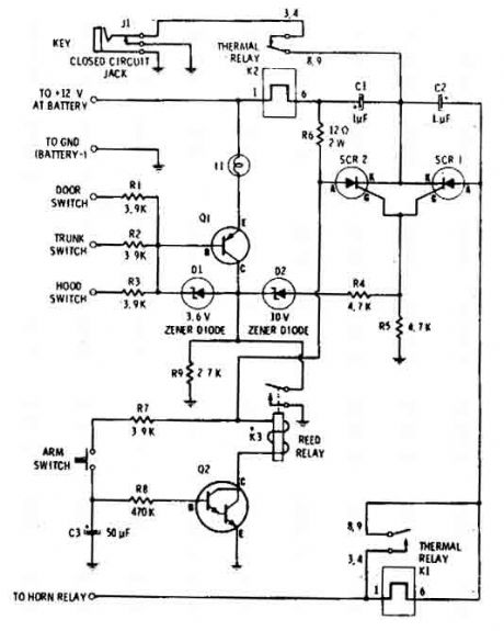
The car alarm here is a simple circuit with basic characteristics that cover all entrances at the car that has switches (doors etc).With one switch (arm-switch) the circuit waits for the sensor-switches to open and to activate it. So the horn with 1 sec pulses will sound imediatelly seconds so the driver can enter in car and disactivate the arming switch. (View)
View full Circuit Diagram | Comments | Reading(1608)
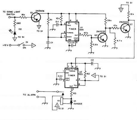
Car alarm circuit using 555 timer
Published:2012/9/11 21:29:00 Author:Ecco | Keyword: Car alarm , 555 timer
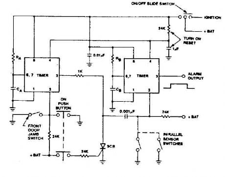
555 timer produces a guaranteed delay, allowing the driver to deactivate the alarm and the elimination of a control switch vulnerable outside. (View)
View full Circuit Diagram | Comments | Reading(2261)
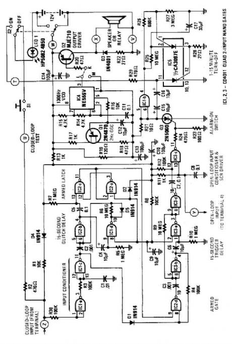
House Alarm Loop Circuit
Published:2012/9/11 21:29:00 Author:Ecco | Keyword: House Alarm , Loop

This circuit offers open and closed loop contacts (switches 1,2,3) that triggers the alarm ON and stays ON for 5 -10 minutes. The trigering delay (entrance/exit) is 27 seconds. This simple alarm circuit Has also a cancel button for reseting the circuit to stand-by mode again. (View)
View full Circuit Diagram | Comments | Reading(1998)
Car Alarm Security Circuit
Published:2012/9/11 21:28:00 Author:Ecco | Keyword: Car Alarm , Security
This car alarm circuit offers 18 seconds delay for the entrance and the exit. It sound continually for 6 minutes and automaticaly turns horn off and gets ready for the next trigering. (View)
View full Circuit Diagram | Comments | Reading(1326)
Simple House Alarm circuit
Published:2012/9/11 21:28:00 Author:Ecco | Keyword: Simple , House Alarm
This house alarm circuit has open and closed loop sensor and has self shutdown function. The delay after trigering can be adjusted from 1 minute to 12. The delay before trigering is 13 seconds. Offcourse all this timmings can be change with litle changes to few passive parts. (View)
View full Circuit Diagram | Comments | Reading(1250)
Clever Car alarm circuit
Published:2012/9/11 21:28:00 Author:Ecco | Keyword: Clever , Car alarm
When this car alarm circuit is activated it stays activated for 80 seconds. It has 15 seconds delay for the driver to enter and deactivate. and All timmings can be altered easilly. (View)
View full Circuit Diagram | Comments | Reading(1315)
Motion Alarm
Published:2012/9/10 21:42:00 Author:Ecco | Keyword: Motion Alarm
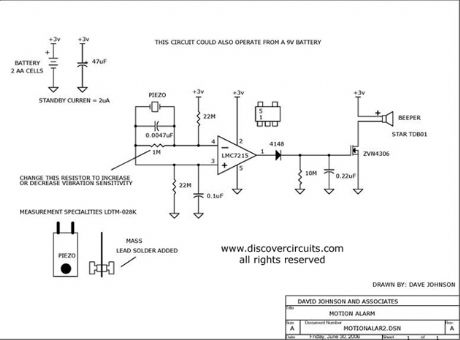
Using a piezoelectric device, this circuit will activate a beeper whenever the circuit is moved. It could be used as an earthquake alarm.
Source: discovercircuits (View)
View full Circuit Diagram | Comments | Reading(1470)
Anti - robbery alarm RCM1A/RCM1B transceiver module
Published:2012/9/10 1:03:00 Author:Ecco | Keyword: Anti - robbery , alarm , transceiver module

The circuit consists of two parts of a tiny radio transmitter and receiver control alarm. The transmitter is supplied by button battery, and it is compact and easy to carry. Once the accident happens, pressing the transmitter button, the receiver will send a very loud alarm sound. The transmitter circuit inlcudes transmitter module RCM1A, button batteries and launch button; wireless receiver alarm circuit is composed of receiver module RCM1B, monostable multivibrator, composite oscillator circuit, audio booster, high-loudness speaker, power supply circuit and other components.
(View)
View full Circuit Diagram | Comments | Reading(1276)
Motion Alarm Using Piezoelectric Device
Published:2012/9/9 20:40:00 Author:Ecco | Keyword: Motion Alarm, Piezoelectric Device

An inexpensive piezoelectric device is used as a motion sensing device for this motion alarm.
Source: discovercircuits (View)
View full Circuit Diagram | Comments | Reading(1288)
AC Line Under/Over Voltage Alarm (March 29, 2009)
Published:2012/9/5 20:51:00 Author:Ecco | Keyword: AC Line , Under/Over Voltage, Alarm

Power lines, which deviate much beyond normal voltages can damage expensive electronic equipment. The circuit below sounds an alarm whenever the line voltage is higher or lower than normal. I set the alarm limits at about +-15% from standard levels. The circuit rectifies and filters the power line signal. I set the resistor values, so the DC voltage produced is close to 1% of the RMS value of the line. Thus, a 120vac line would yield about 1.2v DC. That voltage is fed to a pair of voltage comparators.
Source: discovercircuits (View)
View full Circuit Diagram | Comments | Reading(2547)
WATER SEEPAGE ALARM
Published:2012/9/5 20:44:00 Author:Ecco | Keyword: WATER SEEPAGE, ALARM
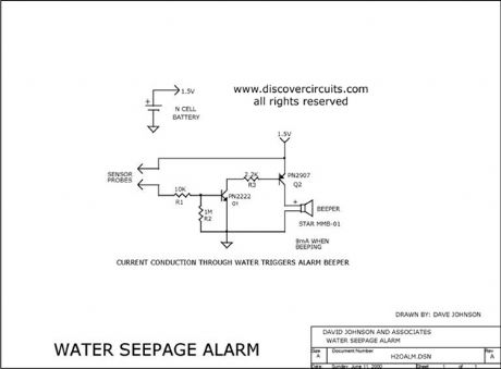
This simple circuit sounds a beeper when its electrodes detect water. It is powered by a single 1.5v N cell. A small 1.5v button battery will also work.
Source: discovercircuits (View)
View full Circuit Diagram | Comments | Reading(0)
Wire Security Loop Alarm
Published:2012/9/4 20:53:00 Author:Ecco | Keyword: Wire , Security , Loop Alarm

A wire loop is used to protect valuable objects in this alarm circuit. The circuit is powered by a 9v battery.
Source: discovercircuits (View)
View full Circuit Diagram | Comments | Reading(994)
ELECTRIC FIELD DISTURBANCE MONITOR - Alarm Discriminator + Battery Monitor
Published:2012/9/4 20:52:00 Author:Ecco | Keyword: ELECTRIC , FIELD DISTURBANCE MONITOR, Alarm Discriminator, + Battery Monitor
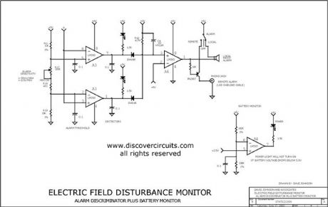
This schematic is the power supply and front-end sections of the field monitor that is discussed in more detail at Electric Field Disturbance Monitor. The system can detect human and animal motion by the electric fields they disturb.
Source: discovercircuits (View)
View full Circuit Diagram | Comments | Reading(10)
ANOTHER VERY LOUD PIEZO ALARM BEEPER
Published:2012/9/4 20:21:00 Author:Ecco | Keyword: ANOTHER , VERY LOUD, PIEZO , ALARM BEEPER

This is yet another beeper circuit that really draws attention. It sweeps the drive frequency slightly to produce a very annoying sound. It uses a transformer to increase the drive voltage across the piezoelectric device to more than 200 volts peak to peak. It cranks out an ear splitting 120db when measured at 12 inches.
Source: discovercircuits (View)
View full Circuit Diagram | Comments | Reading(2359)
| Pages:3/18 123456789101112131415161718 |
Circuit Categories
power supply circuit
Amplifier Circuit
Basic Circuit
LED and Light Circuit
Sensor Circuit
Signal Processing
Electrical Equipment Circuit
Control Circuit
Remote Control Circuit
A/D-D/A Converter Circuit
Audio Circuit
Measuring and Test Circuit
Communication Circuit
Computer-Related Circuit
555 Circuit
Automotive Circuit
Repairing Circuit