
Alarm Control
Index 11
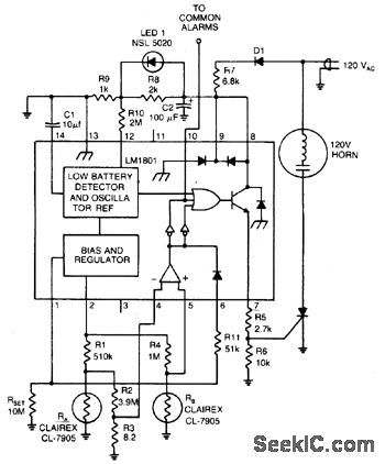
LINE_OPERATED_PHOTO_ELECTRICSMOKE_ALARM_USING_LIGHT_SENSITIVE_RESISTOR(INCLUDESDETEC_TION_OF_OPEN_CIRCUITED_LED)
Published:2009/6/30 3:51:00 Author:May
View full Circuit Diagram | Comments | Reading(793)
POWER_FAILURE_ALARM_1
Published:2009/6/30 3:16:00 Author:May
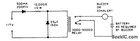
While the power is on,the relay is held open,but when the power fails the buzzercircuit contacts close. (View)
View full Circuit Diagram | Comments | Reading(727)
POWER_FAILURE_ALARM
Published:2009/6/30 3:12:00 Author:May
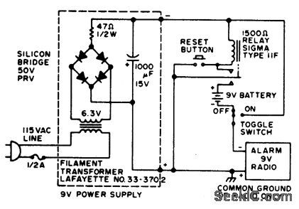
If the power fails, the radio alarm goes on. No loud siren, bell, or whistle. Even if the power is restored, the alarm stays on until RESET button is pushed. (View)
View full Circuit Diagram | Comments | Reading(208)
MICROWAVE_DOPPLER_INTRUSION_ALARM
Published:2009/6/30 2:41:00 Author:May
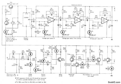
Mullard CL8960 X-band Doppler radar module detects movement of remote target by monitoring Doppler shift in microwave radiation reflected from target. Module consists of Gunn oscillator cavity producing energy to be radiated, mounted alongside mixer cavity that combines reflected energy with sample of oscillator signal. Transmitted frequency is 10.7 GHz. Doppler change is about 31 Hz for relative velocity of 0.45 m/s (1 mph) of relative velocity between object and module, giving AF output for velocities up to 400 mph. Filtered AF is applied through diode pump to trigger of silicon controlled switch TR3 that makes contacts of reed relay open for about 1 s.Relay action is repeated as long as intruder is in monitored area. Report covers circuit operation in detail.-J.E.Saw, Microwave Doppler Intruder Alarms. Mullard, London, 1976, Technical Information 36, TP1570, p 6. (View)
View full Circuit Diagram | Comments | Reading(3588)
LATCHING_ALARM
Published:2009/6/30 2:38:00 Author:May
Closed-circuit alarm drawing only 130 μA of standby current from battery is turned on by opening sensor switch or outing wire. Automatic latching contacts on relay prevent burglar or intruder from deactivating alarm by resetting sensor switch, Relay is Radio Shack 275-004. Sensor can be foil strip around window subiect to breakage.-F. M. Mims, Transistor Projects, Vol. 3, Radio Shack, Fort Worth, TX, 1975, p 75-86. (View)
View full Circuit Diagram | Comments | Reading(1723)
LOW_CURRENT_INTRUDER_ALARM
Published:2009/6/30 2:05:00 Author:May
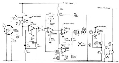
Use of programmable μA776 opamps reduces standby current of infrared alarm to 300 μA, permitting operation from small rechargeable cells. Detector is Mullard RPY86 that responds only to wavelengths above 6 μm, making it immune to sunlight and backgrounds intermittently illuminated by sun. Low-cost mirror is used instead of lens to concentrate infrared radiation on detector. Rd is chosen to make input to first opamp between 2 and 6 V. Circuit energizes alarm relay RL only when incident radiation is changed by movement of intruder in monhored space.- Ceramic Pyroelectric Infrared Detectors, Mullard, London, 1978, Technical Note 79, TP1664, p 8. (View)
View full Circuit Diagram | Comments | Reading(861)
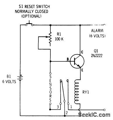
CIRCUIT_BREAKING_ALARM
Published:2009/6/30 2:04:00 Author:May
Operates from small 9-V battery, making it independent of AC power failure. Opening of switch or equivalent breaking of foil conductor removes ground from base of transistor, to energize alarm.-Circuits, 73 Magazine, April 1973, p 132. (View)
View full Circuit Diagram | Comments | Reading(813)
WINDOW_FOIL_ALARM
Published:2009/6/30 2:03:00 Author:May
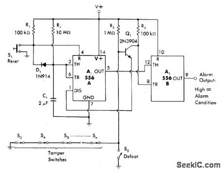
Combination of power-up mono MVBR and latch, using both sections of 556 timer, drives output line high when sensor circuit is opened at door or window switch or by breaking foil on glass. Once alarm is triggered, reclosing of sensor has no effect; S1 must be closed momentarily after restoring sensor circuit to tum alarm off. Circuit includes 22-s power-up delay that prevents triggering of alarm when it is first turned on.-W. G. Jung, IC Timer Cookbook, Howard W. Sams, Indianapolis, IN, 1977, p 231-232. (View)
View full Circuit Diagram | Comments | Reading(1888)
MULTIPLEXED_BURGLAR_ALARM
Published:2009/6/30 1:54:00 Author:May
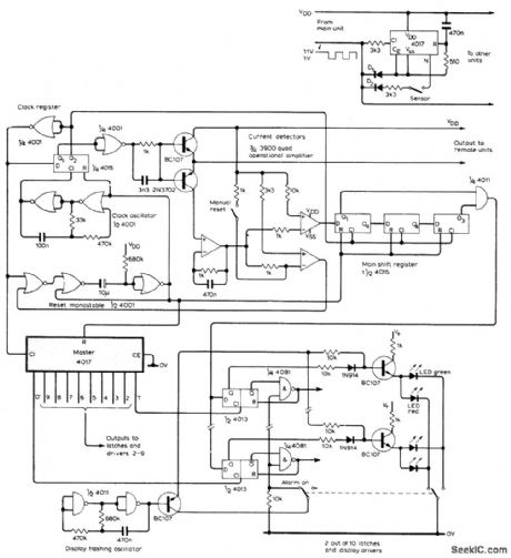
Multiplexing technique provides for detection of state of up to 10 sensors, with immediate identification and location of activated sensor. Only one pair of wires runs from control unit to paralleled remote sensor circuits, one of which is shown at upper right. Each sensor location uses different output from one to zero. Multiplexor circuit is based on 4017 decade counter having 10 individual outputs, to give signals in 10 time slots. Power supply rail is used to reset counter. Clock line is eliminated by switching supply line as square wave. Sensor indication line is eliminated by detecting power supply current drain. Control unit uses oscillator and shift register to generate clocking waveforms. 3900 quad opamp converts sensorline current to logic levels for clocking by master 4017 to control 10 out-put latches and display driver. Two consecutive sensor-open signals are required to activate alarm, minimizing false alarms by interference pulses.-R. J. Chance, Multiplexed Alarm, Wireless World, Nov 1978, p 73-74. (View)
View full Circuit Diagram | Comments | Reading(1637)
FAIL_SAFE_TIMED_ALARM
Published:2009/6/30 1:53:00 Author:May
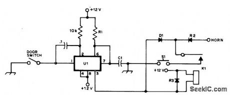
Horn comes on about 30 s after intruder closes door switch by opening car door. Delay is produced by NE555 timer to allow driver to close door after entering or leaving. Thief must keep door open to get leg room for removing equipment under dash. Diodes are 50-PIV 1-A silicon. K1 has 12-V coil. Alarm is set at all times. S1 is normally dosed pushbutton type in door jam. Opening S1 starts timer, and closing it resets alarm.-R. S. Harvey, Junk Box Foils Thieves, QST, Sept. (View)
View full Circuit Diagram | Comments | Reading(1053)
DELAYED_ALARM
Published:2009/6/30 1:45:00 Author:May
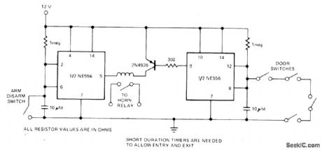
When normally closed arm/disarm switch is opened, first section of NE556 dual timer starts its timing cyde. After delay to allow for entry or exit, pin 5 goes low to energize alarm circuit. Now as long as all door switches are dosed, PNP transistor is kept off because pin 9 is high. When any door switch is opened, transistor tums on after normal delay for owner to enter car, and hom is sounded unless owner closes arm/disarm switch within delay time.- Signetics Analog Data Manual, Signetics, Sunnyvale, CA, 1977, p 724-725. (View)
View full Circuit Diagram | Comments | Reading(0)
SILENT_ALARM
Published:2009/6/30 1:44:00 Author:May
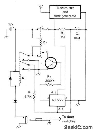
When thief opens car door, relays K1 and K2 activate tone-modulated transmitter, which can be any legal combination of power, frequency, and antenna. A few milliwatts of power should be adequate. Thief hears nothing, but owner is alerted via portable receiver tuned to transmitter frequency. Transmitter remains on about 15 s (determined by R3 and C1) after door is closed until NE555 times out and removes power from transistor. Use any NPN transistor having adequatecurrent rating for relay. If alarm is provided with its own battery and whip antenna, it cannot be disabled from outside of car.-A. Day, Soundless Mobile Alarm, CQ, April 1977, p 11. (View)
View full Circuit Diagram | Comments | Reading(0)
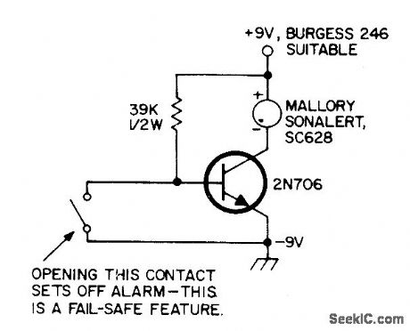
CAR_THEFT_ALARM
Published:2009/6/30 1:42:00 Author:May
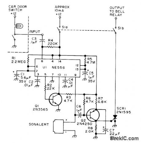
Alarm remains on even if signal from car door switch or other sensor is only momentary, so relay is wired to be selflatching until keyswitch S1 is tumed off. Use hood locks or hood-opening sensors to prevent thief from disabling alarm by cutting battery cable. Circuit indudes time delay of 6 s for entering car and shutting off alarm, to avoid need for extemal keyswitch. Sonalert makes loud tone during 6-s delay period to remind driver that alarm needs to be turned off. At end of 6 s, Sonalert stops and much louder bell is energized to further discourage intruder.-J. Pawlan, The Smart Alarm, 73 Magazind, June 1975. p 37-41. (View)
View full Circuit Diagram | Comments | Reading(1021)
ENTRY_DELAY_ALARM
Published:2009/6/30 1:35:00 Author:May
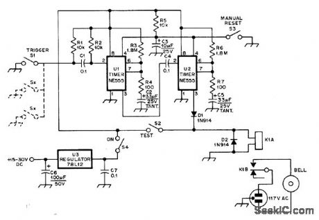
First 555 timer provides delay of about 20 s after triggering by sensor before alarm bell is energized, to allow thief to be caught inside house or give owner time to enter and shut off alarm. Alarm then rings for about 60 s under control of timer U2. Alarm period was set short to attract attention without unduly annoying neighbors.-J. D. Arnold, A Low-Cost Burglar Alarm for Home or Car, QST, June 1978, p 35-36. (View)
View full Circuit Diagram | Comments | Reading(942)
FIVE_INDICATOR_ALARM
Published:2009/6/30 1:32:00 Author:May
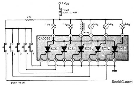
Single five-transistor 10 uses NPN structures on P-type substrate as PNPN silicon controlled switches having common connection for anode (substrate).Relay serving as anode load is energized for actuating alarm if any of the SCS pushbutton switches is closed. Corresponding lamp is energized to identify door or window at which sensor switch has been closed by act of intruder. Alarm remains on until reset by interrupting power supply. Power drain on standby is negligible because SCSs act as open circuits until triggered, permtitting use of batteries for supply. Two or more ICs may be added to get more channels.-H. S. Kothari, Alarm System with Position Indication, Wireless World, Feb. 1976, p 77. (View)
View full Circuit Diagram | Comments | Reading(1040)
RPM_LIMIT_ALARM
Published:2009/6/28 23:31:00 Author:May

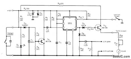
Used with capacitor-discharge ignition system to provide tachometer output along with engine speed control signal. When breaker contacts open, C1 charges and turns Tr1 on, triggering 555 timer used in mono MVBR mode, Resulting positive pulse from 555 fires control SCR through D6 and C6. When contacts dose, D2 isolates C1 to reduce effect of contact bounce. With values shown, for speed limit between 8000 and 9000 rpm, use 0.068 μF for C4 with four-cylinder engine, 0.047 pF for six cylinders, and 0.033 μF for eight cylinders; LED across breaker contacts can be used for setting static timing.-K. Wevill, Trigger Circuit for C.D.l. Systems, Wireless World, Jan. 1978, p 58 (View)
View full Circuit Diagram | Comments | Reading(2768)
ANTENNA_POSITION_CONTBOL
Published:2009/6/28 22:03:00 Author:May
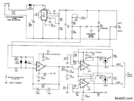
IC logic provides automatic brake release and poshitive povsition control for commercial Ham-M antenna rotator Regulated power supply drives bridge haing position-sensing pot R8 in rotator and R9 in control box When antenna is in desired position, wiper voltages of pots are equal.When R9 is set to new position, voltage difference is amplified by error amplifier U2. Comparators U3 and U4 determine rotation direction needed for rebalance and delivet logic circuits to timing circuit (also given in article) that drives motor and brake release relays.Timer prevents jamming of circuit by operator error.-P. Zander, Automatic Position Control for the HAM-M Rotator, Ham Radio, May 1977, p 42-45. (View)
View full Circuit Diagram | Comments | Reading(2556)
HEADLIGHTS_ON_ALARM
Published:2009/6/28 21:31:00 Author:May
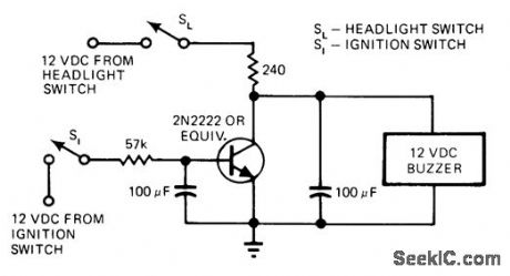
Designed for cars in which headlight switch is nongrounding type, providing 12 V when dosed. When both light and ignition switches are closed, transistor is saturated and there is no voltage drop across it to drive buzzer. If ignition switch is open while lights are on, transistor bias is removed so transistor is effectively open and full 12 V is applied to buzzer through 240-ohm resistor until lights are turned off.-R. E. Hartzell, Jr., Detector Warns You When Headlights Are Left On, EDN Magazine, Nov. 20, 1975, p 160. (View)
View full Circuit Diagram | Comments | Reading(903)
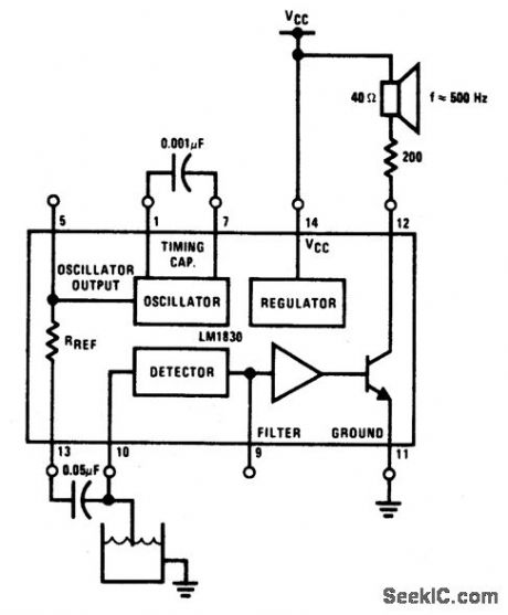
LOW_LEVEL_WARNING_WITH_AUDIO_OUTPUT
Published:2009/6/25 2:53:00 Author:May
View full Circuit Diagram | Comments | Reading(986)
FLOOD_ALARM
Published:2009/6/25 2:51:00 Author:May
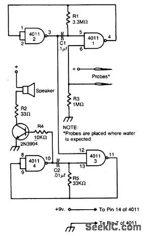
The alarm is built around two audio oscillators, each using two NAND gates. The detection oscillator is gated on by a pair of remote probes. One of the probes is connected to the battery supply, the other to the input of one of the gates. When water flows between the probes, the detection oscillator is gated on.The alarm oscillator is gated on by the output of the detection oscillator. The values given produce an audio tone of about 3000 Hz. The detection oscillator gates this audio tone at a rate of about 3 Hz. The result is a unique pulsating note. Use any 8 ohm speaker to sound the alarm. The 2N3904 can be replaced by any similar NPN transistor. The circuit will work from any six to 12-volt supply. (View)
View full Circuit Diagram | Comments | Reading(3036)
| Pages:11/18 123456789101112131415161718 |
Circuit Categories
power supply circuit
Amplifier Circuit
Basic Circuit
LED and Light Circuit
Sensor Circuit
Signal Processing
Electrical Equipment Circuit
Control Circuit
Remote Control Circuit
A/D-D/A Converter Circuit
Audio Circuit
Measuring and Test Circuit
Communication Circuit
Computer-Related Circuit
555 Circuit
Automotive Circuit
Repairing Circuit