
Alarm Control
Index 14
MOTORCYCLE_BURGLAR_ALARM
Published:2009/6/18 2:00:00 Author:May
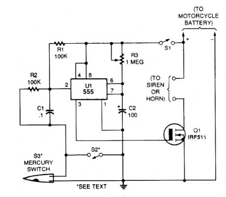
A 555 IC is connected in a one-shot timer cir-cuit that turns on a FET transistor and either a siren or the bike's horn for a preset time period. Switch S1 is used as an on/off switch.Closing either of two switches, S2 and S3, will trigger the IC. When either switch closes, pin 2 of UI goes low. That triggers the IC to produce a positive output at pin 3 and sounds the alarm for the time period set by R3. The mercury switch, S3, is the switch that activates the alarm should anyone move your bike. Switch S2 can be used as a panic switch. (View)
View full Circuit Diagram | Comments | Reading(0)
DOOR_AJAR_INDIGATOR
Published:2009/6/18 1:58:00 Author:May
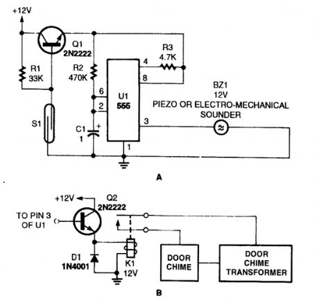
This simple sounder (AJ makes a good door annunciator. If the buzzer is replaced with the circuit in B, the annunciator can be made more pleasant to the ear.
(View)
View full Circuit Diagram | Comments | Reading(1071)
SIMPLE_BIKE_HORN
Published:2009/6/18 1:57:00 Author:May
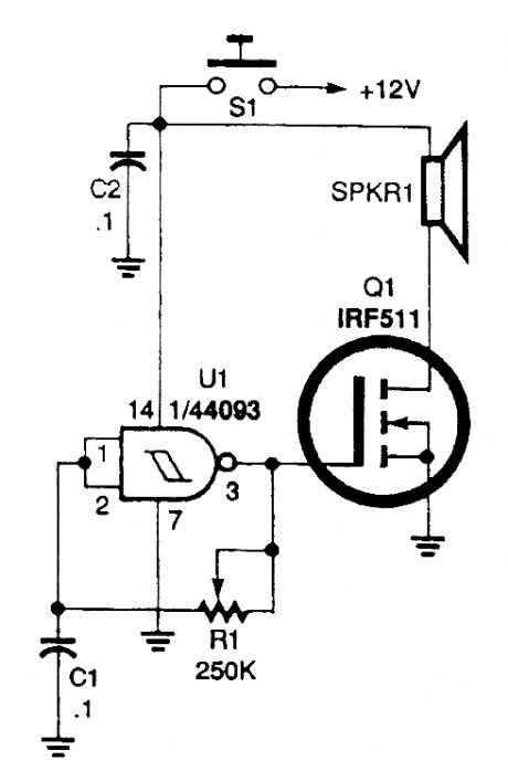
The horn circuit uses only one gate of a 4093 quad 2-input NAND Schmitt trigger, U1, con-nected in a simple, low-frequency, square-wave oscillator circuit. The oscillator's output, at pin 3, drives the gate of Q1. The drain of that FET drives a small horn speaker.Potentiometer RI can be adjusted to set the horn's output frequency. Some horn speakers are frequency sensitive, so play with the oscillator's frequency control for the best or loudest sound. (View)
View full Circuit Diagram | Comments | Reading(2076)
MOTORCYCLE_ALARM
Published:2009/6/17 23:34:00 Author:May
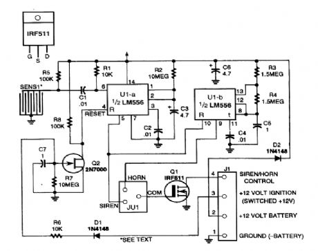
A dual tinter is used to generate a long pulse, which gates a second timer, producing a square wave (nonsymmetrical) and controls the on/off time of the hom. Siren operation can be selected with a jumper. In this case, the output of Q1 will be continuously on and not cycled. Sensor S1 is a row of adjacent circuit board traces with a stainless steel ball bearing laying on them. Any movement causes momentary shorting and opening of the circuit, triggering U1-a. (View)
View full Circuit Diagram | Comments | Reading(155)
CAR_ALARM_DECOY
Published:2009/6/17 23:32:00 Author:May
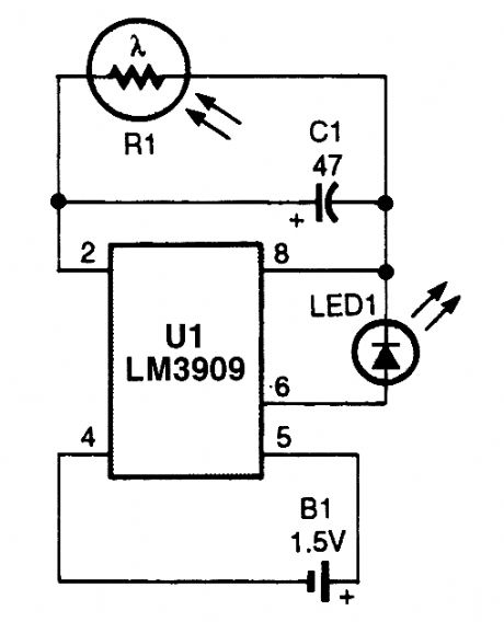
The device will simulate the presence of a burglar alarm in automobiles or homes. Mount RI where daylight can fall on it. During darkness, LED1 flashes, making potential intruders think an alarm system is installed. (View)
View full Circuit Diagram | Comments | Reading(919)
BURGLAR_ALARM_CIRCUIT
Published:2009/6/17 23:18:00 Author:May
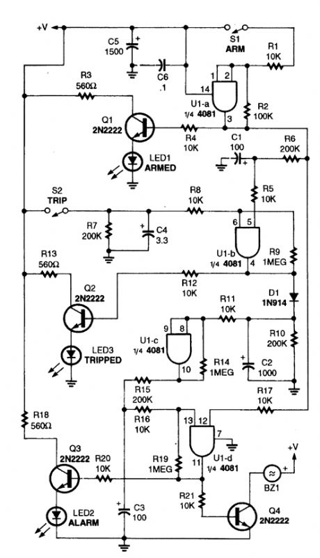
This alarm circuit is built around a single 4081 (CMOS) quad AND gate. It offers an exit and entry delay (around automatically reset two minutes after tripping, provided that the trip input is not left high).The arming switch must go high to arm or low to disarm. After arming, U1-a begins to charge C1 via R6. Around 20 seconds later (af-ter the exit delay), C1 has a sufficient charge to produce a high at the pin-5 input of UI-b.Also, when the circuit is armed, Q1 is turned on to indicate arming, and one input of U1-d is brought high.After the exit delay times out, if the trip in-put opens, it causes an output on gate U1-b.Transistor Q1 is turned on, lighting the trip indi-cator (LED3), C2 instantly charges, and the out-put of U1-c goes high. At that point, C3 begins charging to provide the entry delay.After 20 seconds, C3 has sufficient charge to produce a high at pin 13 of UI -d. That forces UI-d's output high, tuning Q3 and Q4 on, which activates the alarm indicator (LED2) and sounder (BZ1), respectively. If disarmed after a trip pulse, but before the 20-second, entry delay time out, pin 12 of U1-d goes low, so the gate's output does not go high and the alarm does not sound.Components C2 and RIO hold U1-c on for around 2 minutes and 20 seconds to provide the two-minute alarm. After C2's charge drops below half of the supply voltage, U1-c's output goes low, awaiting another trip pulse to set it off again. (View)
View full Circuit Diagram | Comments | Reading(0)
PROXIMITY_ALARM_II
Published:2009/6/17 21:10:00 Author:May
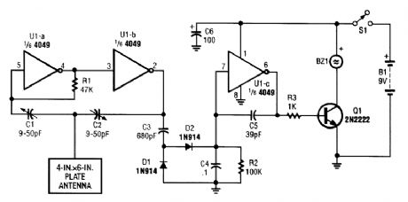
A CMOS logic gate is used to make up this circuit. When an object is near the antenna, the change in oscillator output is detected by D1 and D2 and amplified by U1C, which drives Q1, sound-ing alarm BZ1. (View)
View full Circuit Diagram | Comments | Reading(880)
PROXIMITY_ALARM_I
Published:2009/6/17 21:08:00 Author:May
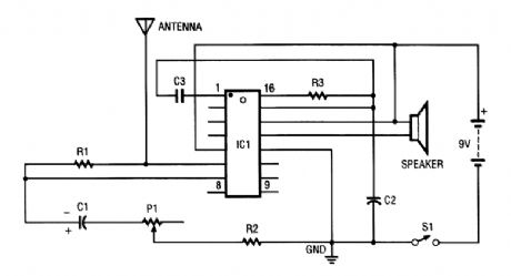
IC1 contains several oscillators and an amplifier. The low-frequency audio-signal oscillator is used to supply an input to the amplifier. That signal is the audio tone that is amplified, then supplied to the speaker by the amplifier.The high-frequency oscillator is purposely set to be very unstable. It is dormant or off until the resistor-capacitor (RC) network is changed. The resistance (fi) in this case is made up of R2 and P1. As the resistance of Pl is decreased, the unit becomes more sensitive (more unstable), and less ca-pacitance (C) is needed to cause the oscillator to oscillate.The capacitance required is provided by C2 and by any capacitance introduced via the antenna loop. When you come near that loop, your inherent body capacitance causes the high-frequency os-cillator to begin to oscillate, which then causes the low-frequency oscillator to be switched on in-ternally. Once the alarm is sounding, the IC is designed so that it latches , that is, it stays on until the power to it is switched off.C1 1-pFAxialCapacitorC2 27-pF Silver Mica CapacitorC3 0.1-pF Mylar CapacitorIC1 CM1001N ICP1 50-kQ Trimmer ResistorR1 75-kQ ResistorR2 200-Q ResistorR3 100-kQ ResistorS1 SPDT SwitchSpk Small SpeakerMisc IC Socket, Battery Snap, Ground Plate, Wire, PC Board (View)
View full Circuit Diagram | Comments | Reading(837)
BINARY_CLOCK
Published:2009/6/17 2:35:00 Author:May
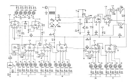
This circuit is an unusual clock in that the LEDs are bi-color red/green displays that indicate the Lime in binary coded decimal form.LEDs 21 through 24 read out secondsLEDs 5, 18, 19, and 20 read out 105 secondsLEDs 14 through 17 read out in minutesLEDs 4, 11, 12, and 13 read out in 105 minutes LEDs 7 through 10 read out the hoursLEDs 1, 2, 3, and 6 read out tens of hoursThe 60-Hz line is used as a timebase. (View)
View full Circuit Diagram | Comments | Reading(2815)
CARRIER_CURRENT_BABY_ALERT_TRANSMITTER
Published:2009/6/17 2:24:00 Author:May
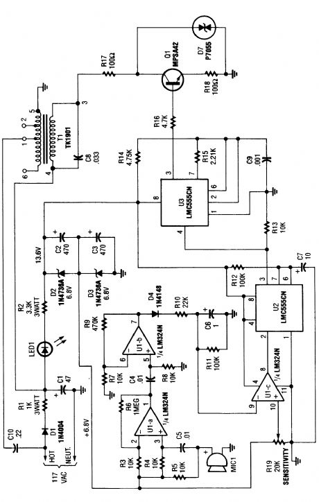
The baby-alert transmitter is built around an LM334 quad op amp(U1), two LMC555CM CMOS oscillator/timers(U2 and U3), and a few support components. The transmitter sends a signal on receipt of a sound at MIC1. It has a frequency of around 125 kHz and can be used to trigger an alarm receiver. (View)
View full Circuit Diagram | Comments | Reading(3024)
SIMPLE_LIGHT_ACTIVATED_ALARM
Published:2009/6/17 2:23:00 Author:May
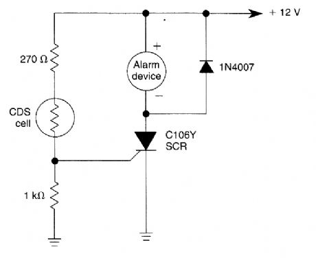
A cadmium-sulfide photocell conducts when a light beam strikes it. This triggers the SCR and activates the alarm device. (View)
View full Circuit Diagram | Comments | Reading(893)
Flash_Signal_Alarm
Published:2009/6/17 0:32:00 Author:May
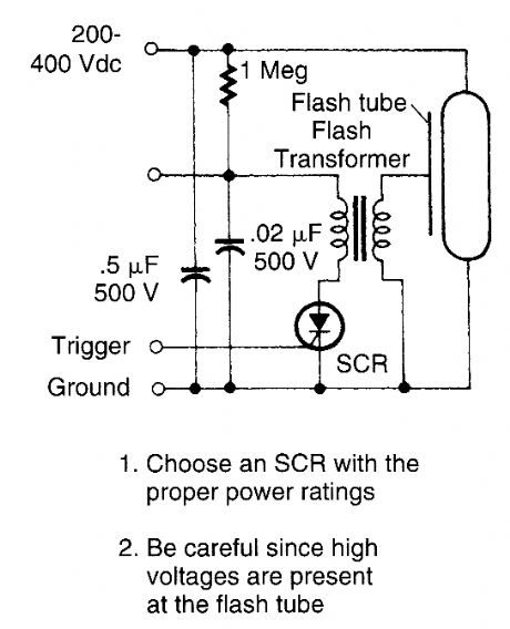
This circuit is useful if you need a low-energy flashing alarm. The 200 to 400-dc supply should have enough internal resistance to charge the 0.5 μF capacitor between flashes, about 2 or 3 time constants, which means about 500 kΩ to 1 MΩ for a 1-s rate. Use lower values for higher rates. (View)
View full Circuit Diagram | Comments | Reading(777)
HEADLIGHT_ALARM
Published:2009/6/16 3:01:00 Author:May
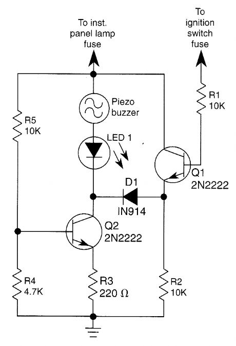
The base of Q1 is connected to the car's ignition circuit; the easiest point to make that connection is at the ignition switch fuse in the car's fuse panel. Also, one side of the piezoelectric buzzer is connected to the instrument-panel light fuse; when the headlights or parking lights are on, the instrument panel is lit, too. When the headlights are off, no current reaches the buzzer. Therefore, nothing happens. What happens when the head-lights are on depends on the state of the ignition switch. When the ignition switch is on, transistors Q1 and Q2 are biased on, effectively removing the buzzer and the LED from the circuit.When the ignition switch is turned off, but the headlight switch remains on, transistor Q1 is turned off, but transistor Q2 continues to be biased on. The result is that the voltage across the piezoelectric buzzer and the LED is sufficient to cause the buzzer to sound loudly and the LED to light. (View)
View full Circuit Diagram | Comments | Reading(386)
ELECTRONIC_DOOR_BUZZER
Published:2009/6/16 2:00:00 Author:May
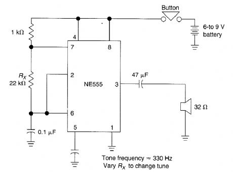
This simple electronic door buzzer draws no quiescent current. When S1 is pressed the speaker produces a tone. The NE555 (U1) generates signal. (View)
View full Circuit Diagram | Comments | Reading(3)
SILENT_ALARM
Published:2009/6/14 23:10:00 Author:May
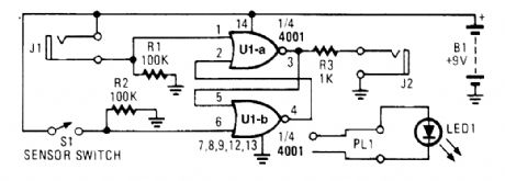
A sensor switch triggers a set-reset flip flop and lights an LED. (View)
View full Circuit Diagram | Comments | Reading(949)
BURGLAR_CHASER
Published:2009/6/14 23:07:00 Author:May
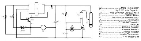
BZ..................... Mtai Horn Buzzer C1 ..............5μF 250 volts Capactto C2.............022μF Green Cap(223 K5K)D1..........................1N4O07 DiodeFT.......... Micro Strobe Tube/ReflectorL1.............................Neon Lamp Q1.................. C174O SW Transistor Q2...............................106 SOP R1......................200 ohm Resistor R2......................820 ohm Resistor R3.......................10 meg ReststorT1...................Invener TransformerT2.................... 4 kV Trtgger Coil
The burglar chaser makes a great accessory for any alarm system. It creates brilliant flashes of white light and a loud, irritating sound from a metal horn buzzer. Transformer T1 is connected to Q1, R1, and R2 to formablocking oscillator. This createsaG-Vac signal on the primary ofT1. Because of T1's large ratio of turns frorn primary to secondary, the 6-Vac signal is stepped up to a level of over 200 Vac, which is then rectified by D1. The resultant dc voltage is applied to storage capacitor C1 and the neon relaxation oscillator made up of R3, C2, and L1. Each time C2 charges up to a sufficient level, it ionizes L1, which causes SCR Q2 to fire. The firing SCR causes the charge on C2 to be applied to the trigger coil. The trigger coil converts the 200 V into the 4000-V pulse that is needed to fire micro xenon strobe tube/reflector FT. The cycle repeats itself after the strobe tube flashes. (View)
View full Circuit Diagram | Comments | Reading(1683)
ALARM_SOUNDER_FOR_FLEX_SWITCH
Published:2009/6/14 23:02:00 Author:May
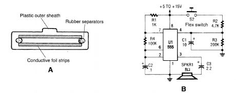
This is a cross-sectional diagram of a flex switch. They can be used as pushbutton or even posi-tion sensors. This schematic diagram shows an oscillator, which is used as an alarm sounder, trig-gered by a flex switch. (View)
View full Circuit Diagram | Comments | Reading(889)
SELF_LATCHING_LIGHT_ALARM_WITH_TONE_OUTPUT
Published:2009/6/14 23:00:00 Author:May
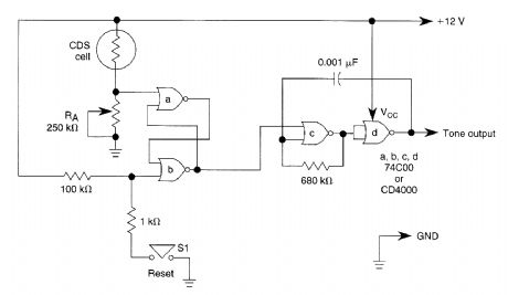
A decrease in the resistance of the CDS cell when light strikes it activates latch a and b, enabling Lone oscillator c and d which produces an output of about 1000 Hz. RA sets the trip level. S1 resets Lhe circuit. (View)
View full Circuit Diagram | Comments | Reading(925)
HIGH_OUTPUT_PULSED_TONE_LIGHT_ACTIVATED_ALARM
Published:2009/6/14 22:58:00 Author:May
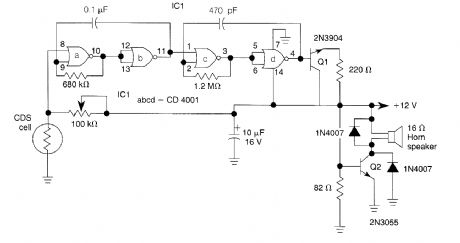
This circuit can produce up to 1 W of audio power to drive a speaker or horn. When the CDS cell is struck by light, its resistance decreases thus activating NOR gate(a) thereby causing(a) and(b) to produce a low-frequency(10-Hz) square wave. This pulses the 1-kHz oscillator(c) and(d), caus-ing it to generate a pulsed 1-kHz tone at a 10-Hz rate. Q1 and Q2 amplify this signal. Q2(2N3055) drives the speaker. (View)
View full Circuit Diagram | Comments | Reading(988)
PRECISION_LIGHT_ALARM_WITH_HYSTERESIS
Published:2009/6/14 22:57:00 Author:May
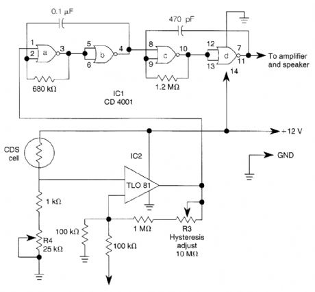
The TL081 is used as a comparator in a Wheatstone bridge circuit. When the CDS cell resistance decreases due to exposure to light, the output from IC2 cause the low-frequency osciLator(a) and(b) to generate a 10-Hz square wave, gating the 1000 Hz oscillator(c) and(d) on and off. This signal dri-ves an amplifier. R3 controls hysteresis, which reduces on-off triggering near the threshold set by R4. (View)
View full Circuit Diagram | Comments | Reading(1434)
| Pages:14/18 123456789101112131415161718 |
Circuit Categories
power supply circuit
Amplifier Circuit
Basic Circuit
LED and Light Circuit
Sensor Circuit
Signal Processing
Electrical Equipment Circuit
Control Circuit
Remote Control Circuit
A/D-D/A Converter Circuit
Audio Circuit
Measuring and Test Circuit
Communication Circuit
Computer-Related Circuit
555 Circuit
Automotive Circuit
Repairing Circuit