
Alarm Control
Index 10
DOPPLER_BURGLAR_ALARM
Published:2009/7/2 3:34:00 Author:May
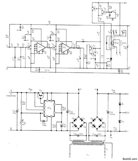
Small radar transmitter operating at 10.687 GHz fills pro-tected area with radio waves. Waves reflected from stationary objects are ignored by receiver, while waves undergoing Doppler shift in fre-quency by reflection from moving object such as intruder are selectively amplified for trigger-ing of alarm. Single waveguide section is di-vided into two cavities, each having Gunn diode; transmitter cavity feeds points A and B of transmitter TR7-IC3, and other cavity feeds points C and D of amplifier that drives alarm relay. Article covers construction and operation of circuit and gives sources (British) for parts and construction khs. Opamps are SN72748 or equivalent, IC3 is μA723 or equivalent, Tr1-Tr3 are ZTX500 or equivalent, Tr4-Tr6 are ZTX302 or equivalent, Tr7 is 3055, D1-D8 are 1N4001 or equivalent, D9-D10 are 1N914, SCR1 is TIC44 or equivalent, Z1-Z2 are BZY88-C8V2, relay is 18-V with 1K coil, Doppler module is Mullard CL8960 or equivalent, and seff-oscillating mixer for re-ceiver is Mullard CL8630S or equivalent. Alarm stays on until reset by appropriate swhch.-M.W. Hosking, Microwave Intruder Alarm, Wire-less World, July 1977, p 36-39. (View)
View full Circuit Diagram | Comments | Reading(1616)
WIRE_CUTTING_ALARM
Published:2009/7/2 3:17:00 Author:May
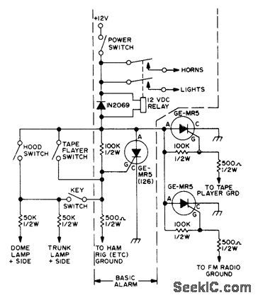
SCR normally acts as open circuit in series with 12-VDC alarm relay because grid is made negative by voltage divider consisting of 100K in series with500 ohms. If ground on 500-ohm resistor is re-moved, as by removal of tape player or CB set from car by thief, gate becomes more posltive and SCR conducts, to energize relay, sound hom, and make headlights shine brightly. Ad-ditional triggering SCRs or alarm switches can be added as shown outside of dashed area for basic alarm.-A. Szablak, Another Burglar Alarm, 73 Magazine, May 1974, p 45-46. (View)
View full Circuit Diagram | Comments | Reading(857)
OPEN_CIRCUIT_ALARM
Published:2009/7/2 3:15:00 Author:May
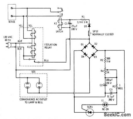
Closing of door or window switch sensor or closing of normally open panic-button switch at bedside and other strategic locations in home trips alarm that sounds loud bell and flashes bright light on and off. Sensor shorts control winding of K1, allow-ing K1 to drop out and apply line voltage to alarm circuit. One AC path is through D5 which rectifies AC for energizing DC latch relay K2 to short sensor lines even though initiating sensor has opened. Simultaneously, AC is applied to diode bridge having SCR between DC legs. C2 starts charging through R2 and R4, and C3 charges through R3. When voltage across C3 reaches about 9O VDC it fires neon and C3 dis-charges into gate of SCR. FuII Iine voltage is then applied to Iamp and bell plugged ;nto Ioad outlets. When C2 drops below holding current, SCR tums off during next AC cycle and Ioad goes off until neon fires again. Setting of 5K pot R4 gives range of 15-80 flashes and hom pulses per seeond. To stop alarm, open SPST switch momentarily.-R. F. Graf and G. J. Whalen, 'The Build-It Book of Safety Electronics, How-ard W Sams, Indianapolis, IN, 1976, p 75-8O. (View)
View full Circuit Diagram | Comments | Reading(1233)
INTRUDER_ALARM
Published:2009/7/2 3:05:00 Author:May
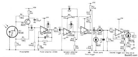
Input is from Mullard RPY86 infrared detector responding to wave-lengths above 6 μm, making it immune to sun-light and backgrounds intermittently illumi-nated by sun. Output signal is produced only when ihcident radiation is changed by movement of intruder in monitored space. Mirrors rather than lenses concentrate incident radia-tion on detector because mirrors do not require high-quality surface finish. Preamp is followed by two amplifier stages, with R10 varying gain of second stage between 10 and 100. Band-width is 0.3-10 Hz. First trigger, having thresh-old of about 1 V, drives second trigger through diode pump to energize alarm relay when in-truder is present.- Ceramic Pyroelectric In-frared Detectors, Mullard, London, 1978, Tech-nical Note 79, TP1664, p 8. (View)
View full Circuit Diagram | Comments | Reading(1968)
PULSED_HORN_ALARM
Published:2009/7/2 3:01:00 Author:May
Two CMOS packages incorporate multiple time delays to improve convenience and effectiveness of auto intrusion alarm. R1C1 gives 30-s delay for arming alarm after it is turned on by switch concealed inside car, to let driver get out of car. R2C2 gives 15-s delay before alarm sounds after door is opened, to allow driver to get back in car again and disable alarm. R3C3 turns off alarm in 300 s and resets alarm system for next intrusion. Car horn is pulsed 60 times per minute, so alarm would not be confused with stuck horn. Article tells how circuit works and gives detailed instruc-tions for instailation and connection to door and trunk switches.-G. Hinkle, Give the Hamburglar Heart Failure, 73Magazine, Feb. 1977, p 36-37. (View)
View full Circuit Diagram | Comments | Reading(916)
HOTEL_ROOM_ALARM
Published:2009/7/1 22:07:00 Author:May
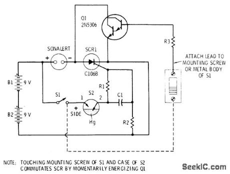
Alarm mounted in flashlight-shaped cylinder is positioned on floor inside hotel room in such a way that it is knocked over by intruder opening door. Mercury switch S2 then triggers SCR and activates Mallory SC-628P pulsed Sonalert alarm. Circuit latches on and can be tumed off only by use of Darlington-amplifier touch switch. Connection from base of Darlington to positive terminal of battery must be made through fingertips as shown by dashed line in orderto silence alarm. Once silenced, S1 can be opened to disconnect latch so alarm can be moved. Other applications include protection of unattended luggage. C1 is 0.1 μF, R1 is 1 megohm, R2 is 1K, R3 is 39K, and S2 is mercury element removed from GE mercury toggle switch,-R. F. Graf and G. J. Whalen, The Build-It Book of Safety Electronics, Howard W. Sams, Indianapolis, IN, 1976, p 19-24. (View)
View full Circuit Diagram | Comments | Reading(1481)
SPEED_ALARM
Published:2009/7/1 21:39:00 Author:May

Frequency detector using two IC timers provides alarm output when input frequency is greater than reference frequency, corresponding to overspeed. Calibrated mono MVBR A1 produces fixed-width positive pulse across R2, with average voltage of pulse varying linearly with input pulse train frequency. ComparatorA2 changes states when integrated output of R3-C1 on pin 5 goes above or below 2-V voltage threshold of A2. With values shown, desired frequency is 1 kHz and circuR detects frequency variation of less than 1%. If low-frequency alarm is desired, connect logic input pin 2 of A2 to reference voltage (pin 4) instead of to ground.-W. G. Jung, IC Timer Cookbook, Howard W. Sams, Indianapolis, IN, 1977, p 228-230. (View)
View full Circuit Diagram | Comments | Reading(0)
BICYCLE_SPEED_ALARM
Published:2009/7/1 19:50:00 Author:May
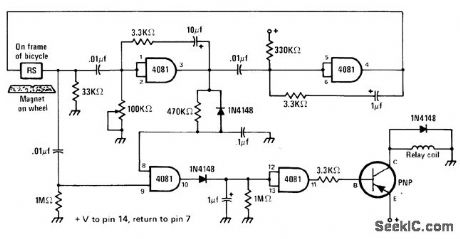
Useful for long-distance bicycling, to indicate when rider drops below predetermined minimum speed. Speed sensor is reed switch attached to frame and tripped once per revolution by permanent magnet mounted on wheel. Rate at which switch closes determines level of DC voltage produced by circuit. When voltage drops below preset level determined by 100K pot, output transistor comei on and energizes relay controlling bicycle hom or other signaling device. Supply can by 9-V transistor battery. Transistor reading should be high enough to handle relay used.-J. Sandler, 9 Projects under $9, Modem Electronics, Sept, 1978, p 35-39. (View)
View full Circuit Diagram | Comments | Reading(1285)
ALARM_CIRCUIT
Published:2009/7/1 3:43:00 Author:May
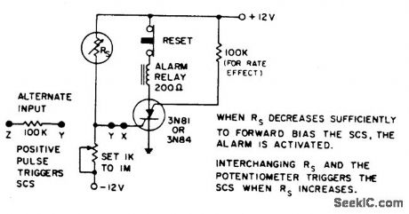
Temperature, light, or radiation sensitive resistors up to 1 megohm readily trigger the alarm when they drop below the value of the preset potentiometer. Alternately, 0.75 V at the input to the 100 kΩ triggers the alarm. Connecting SCS between ground and -12 V permits triggering on negative input to GA. (View)
View full Circuit Diagram | Comments | Reading(955)
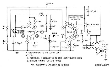
PHOTOELECTRIC_ALARM_SYSTEM
Published:2009/7/1 3:42:00 Author:May

The CA3164A BiMOS detector alarm system and the CA3078 micropower op amp with a photodiode are used as an automatic switch for turning on a night light or sounding a mechanical horn. (View)
View full Circuit Diagram | Comments | Reading(1140)
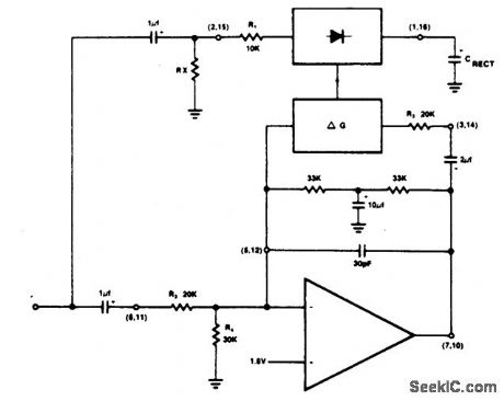
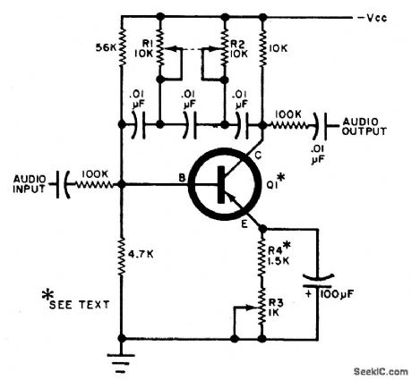
DIFFERENTIAL_VOLTAGE_OR_CURRENT_ALARM
Published:2009/7/1 3:39:00 Author:May
The input may be dc or low frequency ac,The output is a distinctive senes of audiobeeps or a continuous tone,and occurs only when a selected polarity unbalance IS pres-ent at the mput. (View)
View full Circuit Diagram | Comments | Reading(774)
MULTIPLE_ALARM_CIRCUIT
Published:2009/7/1 3:38:00 Author:May
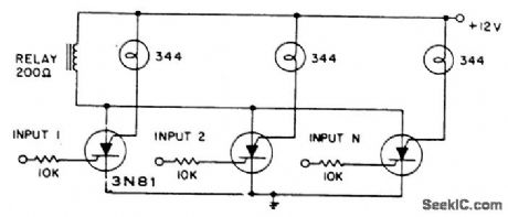
Any of several inputs pulls in the common alarm relay with lamps giving visual indication of triggering input. Low resistance lamps decrease input sensitivity. (View)
View full Circuit Diagram | Comments | Reading(977)
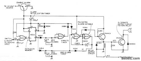
AUTO_BURGLAR_ALARM
Published:2009/7/1 3:37:00 Author:May
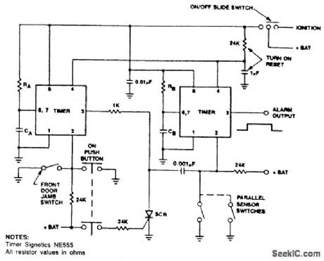
Timer A produces a safeguard delay, allowing the driver to disarm the alarm and eliminating a vulnerable outside control switch. The SCR prevents timer A from triggering timer B, unless timer B is triggered by strategically-located sensor switches. (View)
View full Circuit Diagram | Comments | Reading(0)
ALARM_GENERATOR
Published:2009/7/1 3:26:00 Author:May
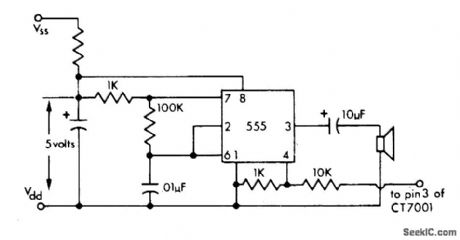
Simple 555 timer generates alarm tone driving small loudspeaker, for use with Cal-Tex CT7001 and other similar digital clocks which do not have internal tone generator. Circuit requires +5 V, but supply can be higher value if suitable dropping resistor is used.-M. S. Robbins, Electronic Clocks and Watches, Howard W. Sams, Indianapolis, IN, 1975,p 91. (View)
View full Circuit Diagram | Comments | Reading(945)
12_h_ALARM
Published:2009/7/1 3:24:00 Author:May
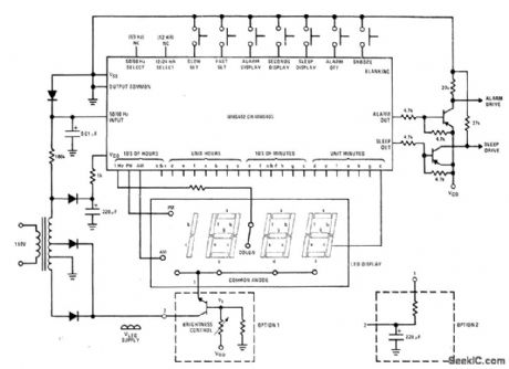
General-purpose digital clock with alarm uses National MM5402 or MM5405 MOS IC to drive 31/2-digit LED display and provide drive for alarm. Brightness control is optional. Sleep output can be used to turn off radio after desired time interval of up to 59 min.- MOS/LSI Databook, National Semiconductor,Santa Clara,CA,1977,p 1-68-1-73. (View)
View full Circuit Diagram | Comments | Reading(4756)
DIGITAL_ALARM
Published:2009/7/1 2:16:00 Author:May
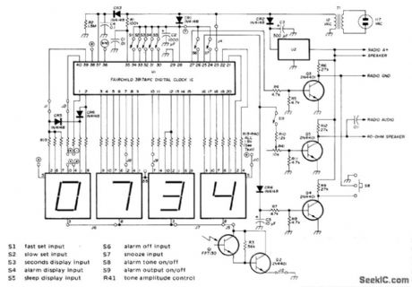
Direct drive offered by Fairchild 3817 IC allows design of simple Iow-cost clock radio providing display drive, alarm, and sleep-to-music features in 12- or 24-h formats.Display is Fairchild FND500 LED. Either 50- or 60-Hz input may be used. U2 is 7800-series IC volt-age regulator rated to meet requirements of radio used. Q3 provides active low output for timed radio turnoff after user-selected interval of up to 59 min. CR4 and C5 rectify alarm-tone output for amplification by Q4 to give active low output for timed radio turn-on when coincidence is detected by alarm comparators. Q5 provides alarm-tone output at level sufficient to drive 40-ohm loudspeaker with ample wake-up volume. If radio is used, omit loudspeaker. Article covers construction and adjustment.-D.Ft. Schmieskors, Jr., Low-Cost Digital Clock, Ham Radio, Feb. 1976,p 26-30.
(View)
View full Circuit Diagram | Comments | Reading(6481)
DOOR_OPEN_ALARM
Published:2009/7/1 0:47:00 Author:May
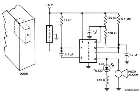
Door open alarms are used chiefly in automotive, industrial, and appliance applications. This type of circuit can sense the opening of a refrigerator door. When the door opens, a triac could be activated to control the inside light. The figure shows a door position alarm. When the door is opened, an LED turns on and the piezo alarm sounds for approximately 5 seconds. This circuit uses a TL3019 Hall-effect device for the door sensor. This normally open switch is located in the door frame. The magnet is mounted in the door. When the door is in the closed position, the TL3019 output goes to logic low, and remains low until the door is opened. This design consists of a TLC555 monostable timer circuit. The 1 μF capacitor and 5.1 M ohm resistor on pins 6 and 7 set the monostable RC time constant. These values allow the LED and piezo alarm to remain on about 5 seconds when triggered. One unusual aspect of this circuit is the method of triggering. Usually a 555 timer circuit is triggered by taking the trigger, pin 2, low which produces a high at the output, pin 3. In this configuration with the door in the closed position, the TL3019 output is held low. The trigger, pin 2, is connected to IA the supply voltage Vgg. When the door opens, a positive high pulse is applied to control pin 5 through a 0.1 μF capacitor and also to reset pin 4. This starts the timing cycle. Both the piezo alarm and the LED visual indicator are activated. (View)
View full Circuit Diagram | Comments | Reading(2920)
PHOTO_ALARM
Published:2009/6/30 23:47:00 Author:May
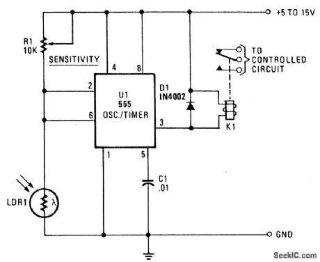
LDR1, a cadmium sulphide (CDS) photoresistive cell is used as the lower leg of a voltage divider between VCC and ground. The timer terminals 2 and 6 are connected to the junction of the photocell and SENSITIVITY control R1. The resistance of the photoresistive cell varies inversely as the light intensity; resistance is high when the illumination level' is low; low in bright light. (The Radio Shack CDS cell 276-116 has a typically wide resistance range-about 3 megohms in darkness and 100 ohms in bright light.) When the light is interrupted or falls below a level set by SENSITIVITY control R1, the rise in LDRl's resistance causes the voltage on pins 2 and 6 to rise. If the control is set so the voltage rises above 2/3 VCC, the relay pulls in. The relay drops out when the light level increases and the drop across the photocell falls below 2/3 VCC. (The circuit can be modified by placing relay K1 and diode Dl between pin 3 and ground. In this case, the relay drops out when the voltage on pins 2 and 6 rises above 2A Vgg, and pulls in when it falls below 1/3 VCC . This modification is valuable when the relay has single-throw contacts.) Opening and closing of the relay contacts occurs at different illumination levels. This 1/3 VCC hysteresis is an advantage that prevents the circuit from hunting and the relay from chattering when there are very small changes in illumination. (View)
View full Circuit Diagram | Comments | Reading(1122)
ALARM_FOR_DIGITAL_CLOCK
Published:2009/6/30 23:16:00 Author:May
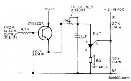
Uses transistor as driver to turn on programmable unijunction transistor (PUT) oscillator feeding 8-ohm loud-speaker. Pitch of tone can be adjusted with 10 K pot. Input is from alarm pin of digital clock IC (pin 3 for Fairchild FCM7001 equivalent of Cal-Tex CTT001}. PUT is Radio Shack 276-119 or equivalent.-W. J. Prudhomme, CT7001 Clock-buster, 73 Magazine, Dec. 1976, p 52-54 and 56-58. (View)
View full Circuit Diagram | Comments | Reading(2828)
6-DIGIT_WITH_CALENDAR_AND_ALARMS
Published:2009/6/30 22:55:00 Author:May

Circult is built around Cal-Tex CT7001 IC that includes outputs for displaying day of monthalong with time on Liftonix DL707 LED read-outs. Transistor switch Q1 and relay form timer triggered by IC to control radio or other appli-ance drawing up to 5 A from AC Iine. Dual-volt-age power supply provideg 7 and 14 VDC. Includes snooze alarm along with regular built-intransistor-driven buzzer.-M. s. Robbins, Electronic Clocks and Watches, Howard W.Sams, Indianapolis,IN,1975,p 103-104 and116-117. (View)
View full Circuit Diagram | Comments | Reading(1337)
| Pages:10/18 123456789101112131415161718 |
Circuit Categories
power supply circuit
Amplifier Circuit
Basic Circuit
LED and Light Circuit
Sensor Circuit
Signal Processing
Electrical Equipment Circuit
Control Circuit
Remote Control Circuit
A/D-D/A Converter Circuit
Audio Circuit
Measuring and Test Circuit
Communication Circuit
Computer-Related Circuit
555 Circuit
Automotive Circuit
Repairing Circuit