
Alarm Control
Index
American siren alarm circuit
Published:2014/1/24 20:22:00 Author:lynne | Keyword: American siren alarm circuit,
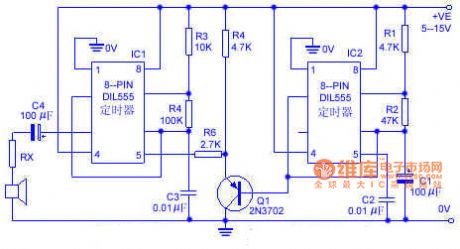
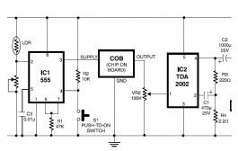
The circuit simulation an American siren sounds. IC2 is connected to a low-frequency multivibrator, the oscillation period is about 6s. C1 slowly changing ramp waveform applied to the PNP emitter follower Q1, and then applied to FM alarm generator IC1 through R6. IC1 natural center frequency of about 800Hz. Operation of the circuit is: alarm output signal from a low-frequency start, and then gradually rises to a high frequency within 3s, then dropped in the 3s to the original low frequency, and so forth continue. American siren alarm circuit shown in Figure:
(View)
View full Circuit Diagram | Comments | Reading(1562)
Lu lian intelligent remote alarm system electric schematic diagram
Published:2014/1/19 21:52:00 Author:lynne | Keyword: Lu lian intelligent remote alarm system electric schematic diagram,
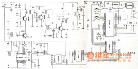
Lu lian intelligent remote alarm system electric schematic diagram as shown:
(View)
View full Circuit Diagram | Comments | Reading(1727)
Multi-channel burglar alarm circuit diagram
Published:2014/1/19 21:46:00 Author:lynne | Keyword: Multi-channel burglar alarm circuit diagram,
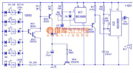
This alarm can be 6-way, from 0 to 30 km on the touch line in both sound and lighting for monitoring. Works in the following figure:Using 6 inverter C033 and light-emitting diodes (leds) as a touch alarm display. When the body contact (directly and/or wear gloves and indirect touch) when any one end in A ~ F, the end brings low potential, the inverter makes light-emitting tube LED display. At this moment, BG1 ~ BG4 conduction, C1 charging, acoustics part (IC1, IC2, etc.) begin to work. IC1, produce about 1 hz sawtooth wave by BG5 buffer to add to the IC2 modulation, IC1 oscillation frequency from low to high, the speaker sends out the similar public security police car alarm.
Use installation should pay attention to the Q end reliable to use A wire from the earth, A ~ F side respectively with bare copper wire to the surveillance, fixed place need porcelain insulation, at the same time pay attention to the rain, water, etc. Between cause and to form A low impedance. The alarm sensitivity is extremely high, standing on a chair touch wires can also call the police, the human body to leave after the all-clear to delay a few seconds. Power supply adopts 8 batteries. Adjust the R6 can change the tone. (View)
View full Circuit Diagram | Comments | Reading(2217)
PIC12F675 Microcontroller Based Security Alarm Circuit
Published:2013/8/29 1:19:00 Author:lynne | Keyword: PIC12F675 Microcontroller Based Security Alarm Circuit

The output of the PIR sensor module (PIR1) is monitored through GP5 (pin 2) of PIC12F675. PIC12F675 is an 8-Pin Flash-Based 8-Bit CMOS Microcontroller. Note that,here the PIC12F675 microcontroller uses the internal clock oscillator at 4.0 MHz. When the motion is sensed, this output is high at about 3.3 V . You could still use this voltage as a valid logic high for IC1 by changing the code , but It is preferred to use this voltage to drive the base of a BC547 transistor (T1) so that at the collector we will have the full swing of the logic voltages.
When power supply is turned on by the on/off switch (S1), IC1 monitors the voltage at the collector of the transistor after a delay of about 60 seconds. This initial delay is introduced deliberately to avoid false triggerings, because the PIR sensor requires an initial stabilization time of about 10 to 60 seconds in order to function properly. A red LED (LED1) is connected to port GP0 of IC1 (pin7) with a current limiting resistor (R3) in series. The LED blinks at a slow rate during this delay time.
After this delay, IC1 starts monitoring the voltage at the collector of T1. The LED blinking pattern is now changed to indicate the “standby” mode. In standby mode, T1 is cut off, and the collector output is at logic high (+5 V). When a “valid” motion is sensed, the high output from the PIR sensor module saturates the transistor and the voltage at the collector drops down to logic low. Consequently, of port GP1 (pin 6) of IC1 goes high to switch on the 5V DPDT relay (RL1) through transistor T2. This output will remain High, as long as the motion exists, and this active condition is indicated by a steady-glow of LED1. DPDT Switching contacts of RL1 can be connected to powerful external lamps and/or alarms.
(View)
View full Circuit Diagram | Comments | Reading(2722)
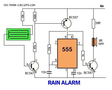
RAIN ALARM
Published:2013/8/5 20:42:00 Author:lynne | Keyword: RAIN ALARM
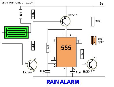
This circuit consumes no current until moisture is detected on the rain plate.
(View)
View full Circuit Diagram | Comments | Reading(0)
General Purpose Alarm Circuit for Resistive Sensor circuit
Published:2013/3/29 4:35:00 Author:Ecco | Keyword: General Purpose Alarm , Resistive Sensor
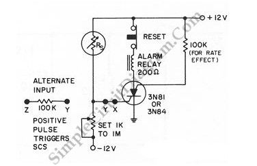
When the resistance value of a temperature, light, pressure, or any other resistive sensors Rs drops below a certain point (adjusted by a preset potentiometer), the SCR (silicon controlled switch) will be triggered. The sensor (Rs) and the potentiometer placement can be interchanged to get opposite action, where the SCR need to be triggered at the increase of sensing resistor (Rs). Here is the schematic diagram of the circuit:
(View)
View full Circuit Diagram | Comments | Reading(1348)
Arduino Panic Alarm
Published:2013/3/27 4:16:00 Author:Ecco | Keyword: Arduino Panic Alarm
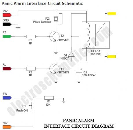
Panic Alarm circuit consists of two equally important parts. The first part is the ready-made Arduino Microcontroller board, and the second part is an interface circuit which can be wired on a piece of prototyping board. You can use any standard 9V battery to power the whole circuit, and the Push-ON (push ‘n’ hold) switch (S1) to activate the alarm function. An additional Electro-Magnetic Relay (EMR) is also attached to the interface circuit.
(View)
View full Circuit Diagram | Comments | Reading(1416)
Touch Alarm System
Published:2013/3/25 4:25:00 Author:Ecco | Keyword: Touch Alarm System
Touch Alarm circuit is widely used for security, which is installed on the door. The advantages of this alarm is because the cost is cheap and difficult to detect by burglars / intruders.
(View)
View full Circuit Diagram | Comments | Reading(1791)
Easy Build Motorcycle Alarm
Published:2013/3/25 4:16:00 Author:Ecco | Keyword: Easy Build Motorcycle, Alarm
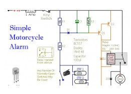
The following circuit is a simple, cheap and easy build motorcycle alarm. The circuit just required 2 transistors to drive the relay the the relay act as a switch to activate the buzzer. Any number of normally-open switches may possibly be applied.
(View)
View full Circuit Diagram | Comments | Reading(1462)
Electronic Siren based NE555
Published:2013/3/25 4:04:00 Author:Ecco | Keyword: Electronic Siren
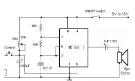
Here the circuit diagram of electronic siren based NE555. This circuit produces a sound like factory siren. It applies a 555 timer IC which is utilized as an astable multivibrator of a center frequency of about 300Hz. The frequency is controlled by the pin 5 of the IC.
(View)
View full Circuit Diagram | Comments | Reading(1540)
Pyroelectric Fire Alarm System
Published:2013/3/25 4:02:00 Author:Ecco | Keyword: Pyroelectric , Fire Alarm System

This is definitely an ultra-sensitive fire sensor that exploits the direct piezoelectric property of an ordinary piezo component to recognize the fire. The lead zirconate titanate crystals within the piezo component have the property to deform and produce an electrical potential when heated, thus converting the piezo component into a heat sensor.
(View)
View full Circuit Diagram | Comments | Reading(1282)
Multitone Siren Alarm
Published:2013/3/25 4:01:00 Author:Ecco | Keyword: Multitone Siren Alarm
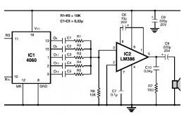
Here the simple schematic of multitone siren alarm circuit. This multitone siren is effective for reverse horns, burlgar alarms, and many others. It generates five various audio tones and is much more earcatching than a single-tone siren.
(View)
View full Circuit Diagram | Comments | Reading(1532)
Fire Alarm with LDR Sensor
Published:2013/3/25 3:48:00 Author:Ecco | Keyword: Fire Alarm , LDR Sensor
This is the fire alarm circuit which use LDR to sense the smoke from the fire, so it can be used to detect any dark smoke. With the onset of summer season, possibilities of fire accidents go up. These fire accidents could be prevented if timely alarms are available. The circuit given right here alerts the user against these fire accidents.
(View)
View full Circuit Diagram | Comments | Reading(1473)
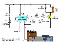
Cheap Motorcycle Alarm
Published:2013/3/25 3:47:00 Author:Ecco | Keyword: Cheap Motorcycle Alarm

This is simple to build and cheap motorcycle alarm circuit which could be fitted in motorcycles to take care of them from getting stolen. The tiny circuit may be hidden anyplace, without having any difficult wiring. Practically, it fits all motorcycles as long as they’ve a electric battery.
(View)
View full Circuit Diagram | Comments | Reading(1324)
Power Supply Failure Alarm
Published:2013/3/25 3:44:00 Author:Ecco | Keyword: Power Supply, Failure Alarm

This is the ‘special’ circuit design of power supply failure alarm. The vast majority of the power supply failure alarm / indicator circuits require a independent power supply for themselves. However the alarm circuit introduced right here requires no extra supply power source.
(View)
View full Circuit Diagram | Comments | Reading(1187)
Notebook Anti Theft Protector
Published:2013/3/25 3:43:00 Author:Ecco | Keyword: Notebook, Anti Theft Protector
Here the notebook anti theft protector circuit to secure your important netbook / notebook from stealing. Basically, this is a mini security alarm generator. Fixed inside the notebook case, it will definitely sound a noisy alarm when a person attempts to grab the notebook. This very sensitive circuit utilizes a homemade tilt switch to turn on the alarm system through tilting of the laptop computer case.
(View)
View full Circuit Diagram | Comments | Reading(1142)
RAIN ALARM Circuit
Published:2013/3/5 20:39:00 Author:Ecco | Keyword: RAIN ALARM
This circuit consumes no current until moisture is detected on the rain plate.
(View)
View full Circuit Diagram | Comments | Reading(2216)
DUMMY ALARM Circuit
Published:2013/3/4 21:48:00 Author:Ecco | Keyword: DUMMY ALARM
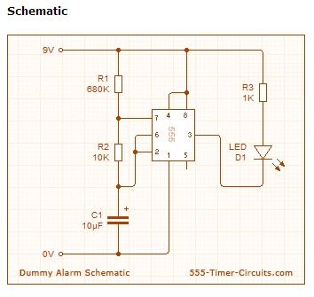
This Dummy Alarm project makes an LED flash briefly once every 5 seconds to imitate the indicator light of a real alarm. Overview The circuit is designed to use very little current to prolong battery life so that it can be left on permanently. An on/off switch is not included, but could be added if you wish. The 7555 timer IC used is a low power version of the standard 555 timer. A 憇uperbright?red LED is used because this provides a bright flash with a low current. The LED is off for most of the time so the average total current for the circuit is less than 0.2mA. With this very low current a set of 3 alkaline AA cells should last for several months, maybe as long as a year.
(View)
View full Circuit Diagram | Comments | Reading(1402)
The detection and alarm device circuit with laser rod
Published:2013/2/19 1:00:00 Author:Ecco | Keyword: detection , alarm device, laser rod
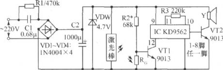
Analog sound ICs form a receiving circuit, usually the laser emitted by laser rod is irradiated on photoresistor RG, RG shows low resistance, the transistor VT1 is cut-off because of base's low potential, then IC does not work, speaker Y does not emit sound. Once a person or object comes into the alert zone, RG resistance increases due to the less than light, VT1 base potential rises to get saturated conduction, then IC is energized.
(View)
View full Circuit Diagram | Comments | Reading(1094)
Multi-channel laser burglar alarm circuit
Published:2013/2/17 21:00:00 Author:Ecco | Keyword: Multi-channel laser, burglar alarm
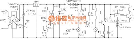
VT1, VT2, RL1, RP1, R1, K and VD6 constitute light control switch, in the daytime, photoresistor RL1 is in a low resistance state, VT1 gets saturated conduction, VT2 is turned off, K relay is not energized, normally open contact J is in a disconnected state, the alarm circuit does not work; at night, RL1 becomes high impedance, VT1 is deadline, VT2 gets saturated conduction, K gets electrical to make J pull in, then the circuit supplies for the whole machine, red light-emitting diode is lit.
(View)
View full Circuit Diagram | Comments | Reading(1305)
| Pages:1/18 123456789101112131415161718 |
Circuit Categories
power supply circuit
Amplifier Circuit
Basic Circuit
LED and Light Circuit
Sensor Circuit
Signal Processing
Electrical Equipment Circuit
Control Circuit
Remote Control Circuit
A/D-D/A Converter Circuit
Audio Circuit
Measuring and Test Circuit
Communication Circuit
Computer-Related Circuit
555 Circuit
Automotive Circuit
Repairing Circuit