
Alarm Control
Index 7
DIFFERENTIA_L_VOLTAGE_ALARM
Published:2009/7/9 23:39:00 Author:May

Deleclor circuit with high sensitivity and stability, followed by audio ampliler, serves as differential voltage or current alarm. Input may be d-c or low-frequency a-c. Output is distinctive series of audio beeps or continuous tone, occurring only when preselected polarity unbalance is present at input.-C. E. Miller, Differentktl-Voltage or Current Alarm Circuit, EEE, 12:7, p 25. (View)
View full Circuit Diagram | Comments | Reading(938)
INFRARED_BURGLAR_ALARM
Published:2009/7/9 23:37:00 Author:May
Has electronically modulated infrared light source and synchronous phase sensitive demodulator pick up unit. Pulsed-light technique overcomes adverse effects of continuous or varying ambient light.Alarm goes off if power supply or interconnecting wires are tampered with.Floating 12-v battery takes over load only if power supply fails.C1 tunes T1 to 55-cps oscillator frepuency.-S.Bagno and J.Fasal,Intruder Alarm Uses Phase-Sensitive Detector,Electronics,31:7,p 102-105.
(View)
View full Circuit Diagram | Comments | Reading(1028)
VOLTAGE_SENSING_ALARM
Published:2009/7/9 23:36:00 Author:May
Silicon controlled switch is triggered by input signal more than 1 v above or below ground.- Transistor Manucal, Seventh Edition, General Electric Co., 1964, p 425. (View)
View full Circuit Diagram | Comments | Reading(777)
POSITIVE_UMIT_ALARM
Published:2009/7/9 23:34:00 Author:May
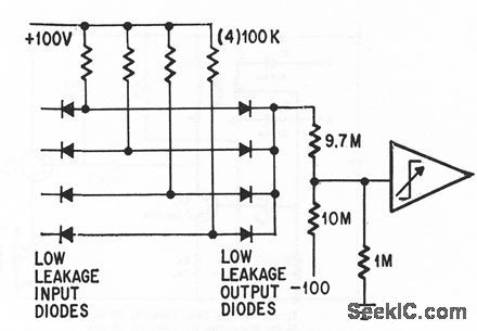
Operafional trigger trips when any output of analog computer goes off scale (above +99 v).-P. Lefferts, Operationctl Trigger For Predse Control, Electronics, 37:28, p 50-55. (View)
View full Circuit Diagram | Comments | Reading(736)
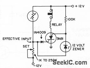
LOW_VOLTAGE_ALARM
Published:2009/7/9 23:34:00 Author:May
Two-transistor alarm senses 0.2-v drop in telephone system und turns on loctd or remote signalling apparatus.If relay and R3 are interchcnged, circuit will opera as high-voltage alarm,-C.J. Kieffer,Simple Low-Voltage Alarm,Electronics,35:18,p 44-45. (View)
View full Circuit Diagram | Comments | Reading(288)
SHORT_CIRCUIT_ALARM
Published:2009/7/9 23:32:00 Author:May
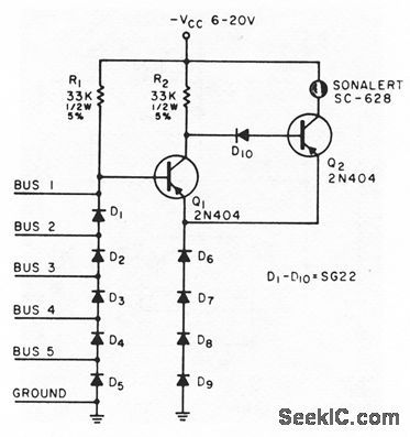
Sounds an alarm if a short occurs between any two of five different voltage buses or between any bus and ground.Used in checking complicted point-to point backplane wiring for computers,to detect wiring errors or solder splashes.-J.J.Russo,Short-Circuit Alarm,EEE,13:6,p 66-68. (View)
View full Circuit Diagram | Comments | Reading(872)
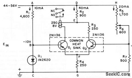
MULTIPLE_INPUT__OVERVOLTAGE__ALARM
Published:2009/7/9 23:27:00 Author:May
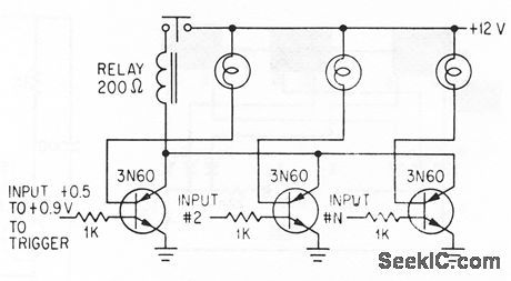
Lamp load of each silicon-contralled switch lights when its input exceeds threshold voliage,to identify input that is responsible for pulling In relay that sounds alarm or shutsdown equipment Lamps aIso serve to suppress rate effect-R.A.Stasior How to suppress Rale Effect in PNPN Devices,Electronics,37:2, p 30-33. (View)
View full Circuit Diagram | Comments | Reading(877)
VHF_INTRUSION_ALARM
Published:2009/7/9 23:25:00 Author:May

Based on fact that object moving toward or away from antenna causes phase relationship of radiated and reflected waves to shift through 2 pi radians at antenna for each half-wave length of movement. Varying phase changes amplitude of oscillation, detected by circuit and used to turn on alarm. Drift in oscillator grid voltage activates timing motor which adjusts degree of coupling between oscillator tank and antenna, to make alarm self-adjusting.-G. A.Whitlow, VHF Intrusion Alarm is Self-Adiusting, Electronics, 3235, p 62-66. (View)
View full Circuit Diagram | Comments | Reading(734)
COMPUTER_FAULT_ALARM
Published:2009/7/9 23:22:00 Author:May
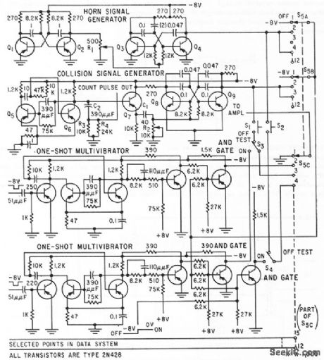
AudibIe alarm system gives distinctive indication of fault loccttion in digitcd computer and data processing equipment. Hom cnd collision signcd sounds are generctted by electronic circuits shown, for monitoring two circuits. Mixing those two signals produces battle stations sound for monitoring third circuit.-S. Fierston, Alarm Circuit Warns of Faults in Digital Systems, Electronics, 32:27, p 48-49. (View)
View full Circuit Diagram | Comments | Reading(836)
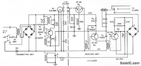
TRIP_WIRE_ALARM
Published:2009/7/9 23:13:00 Author:May

Control circuit tums converter, transmitter, and modulator on through relay contacts, to make 1,680-kc hybrid transmitter send tone-modukned signals to central station when trip wire is broken by ava lanche. Daylight on photocell initiates test transmission dcdly.-G.Neal and S. A. Stone, Hybrid Telemeter Detects Avalanches, Electtonics, 34:50, p 72-73.
(View)
View full Circuit Diagram | Comments | Reading(1000)
PRINTER_ERROR_ALARM
Published:2009/7/9 23:12:00 Author:May

When a printer is shut down, this alarm sounds an alarm. The input can be either a high-to-low or low-to-high transition. This can be a logic level that corresponds with the printer being on or off. The oscillator produces an interrupted (on-off) tone. (View)
View full Circuit Diagram | Comments | Reading(872)
INTRUDER_ALARM
Published:2009/7/9 23:08:00 Author:May
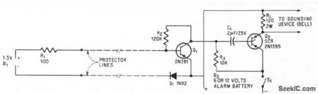
Circuit responds to break or short in loop of foil or wire encircling area to be protected, by reacting to change in normal current droin of 500 microamp from l.5.v battery in protector loop. Circuit is reset after alarm by opening SI1 momentarily,-W. Vollenweidel,Low-Current Alarm,Electronics,39:5,p 105-106.
(View)
View full Circuit Diagram | Comments | Reading(0)
CMOS_SHORT_PULSE_GENERATOR
Published:2009/7/9 21:48:00 Author:May
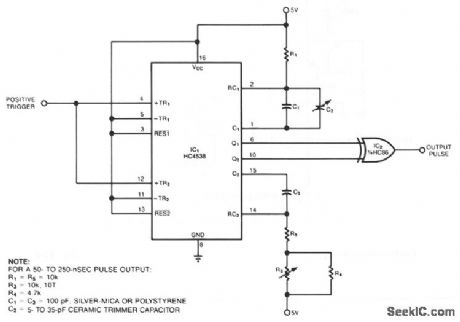
Comprising two low-power, CMOS chips, the pulse generator produces a precise pulse width in the 50 to 500 ns range. IC1 is a dual monostable multivibrator (one shot) in which each positive trigger pulse initiates simultaneous positive output pulses at pins 6 and 10. In response, XOR gate IC2 produces a positive pulse whose duration is equal to the difference between the two input-pulse durations. Section 1 of the one shot generates an approximate 1-μs reference pulse-shorter pulses are more susceptible to manu-facturing variations caused by parasitic layout capacitance. Variable capacitor C2 lets you adjust this pulse width. Section 2 of the one shot generates a variable-length pulse; you adjust its width by using potentiometer R3. Resistors R4 and R5 set the output pulse's maximum and minimum width, respectively. Because the XOR gate's rise and fall times are about 20 ns for reasonable values of load capacitance, you should calibrate the circuit using C2 for a minimum output-width of 50 ns. (View)
View full Circuit Diagram | Comments | Reading(1767)
BURGLAR_ALARM_WITH_NC_AND_NO_SWITCHES
Published:2009/7/9 21:47:00 Author:May
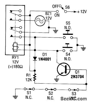
This circuit uses both NC and N0 sensors. Series NC sensors allow Q1 to activate RY1. NO sensors directly activate RY1. (View)
View full Circuit Diagram | Comments | Reading(765)
SIMPLE_BURGLAR_ALARM_1
Published:2009/7/9 21:41:00 Author:May
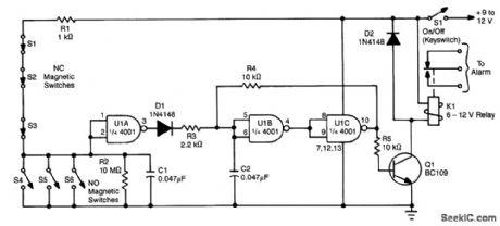
Using one IC and a driver transistor, this simple alarm uses either NO or NC sensors,When a sensoroperates,the input to U1A goes low,causmg U1A to go high,U1B low,and U1C high.This biases Q1 ONand activates relay K1.On/offis vla keyswitch S1. (View)
View full Circuit Diagram | Comments | Reading(798)
SIMPLE_BURGLAR_ALARM
Published:2009/7/9 21:39:00 Author:May
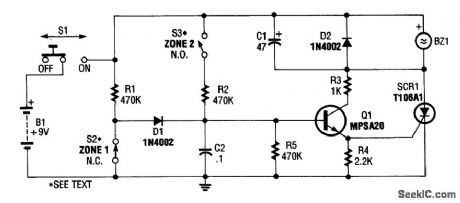
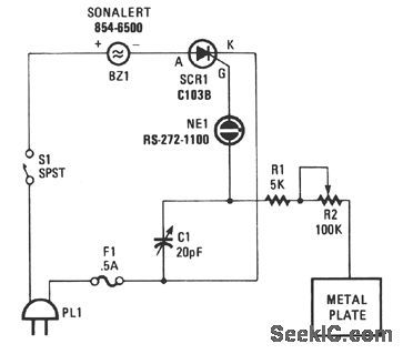
A simple circuit using either NO or NC sensors uses an RC delay circuit (R2/C2 or R1/C2) to drive emitter-follower Q1, switching SCR1 and buzzer (or bell) BZ1. S1 is used for activation and reset. (View)
View full Circuit Diagram | Comments | Reading(905)
SCR_PROXIMITY_ALARM
Published:2009/7/9 21:38:00 Author:May
View full Circuit Diagram | Comments | Reading(766)
SELF_LATCHING_BURGLAR_ALARM
Published:2009/7/9 21:31:00 Author:May
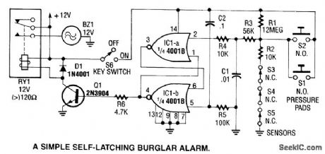
This alarm uses IC1A and IC1B as a latch. When sensors S1 through S5 activate, IC1A turns on and forces IC1B to cut off. Q1 drives RY1. (View)
View full Circuit Diagram | Comments | Reading(941)
CAPACITIVE_SENSOR_ALARM
Published:2009/7/9 21:24:00 Author:May


The unit is constructed around a balanced-bridge circuit, using both capacitance and inductance. The bridge consists of capacitors C2 and C3, and the center-tapped winding of T1. One end of the bridge is coupled to ground by C4, while capacitance changes are introduced through C1. A small capacitance change unbalances the bridge and produces an ac signal at the base of Q1. Transistors Q1 and Q2 are connected to form a modifted-Darlington amplifier. The collector load for Q2 is a separate winding of T1 that is connected out-of-phase with the incoming ac signal. That produces a large, distorted signal each time the bridge is unbalanced.The distorted signal is taken from the bridge circuit by a third winding of transformer T1. That signal is then rectified by D6 and applied as a dc signal to the base of Q3. The applied signal energizes the relay, K1, as soon as the unbalanced condition occurs, and the relay drops out as soon as the circuit balance is restored. Of course, for normal alarm use, the relay should be made self-latching, so that the alarm condition remains in effect until the system is reset.An audible alarm, such as a bell or klaxon horn, can be operated from the relay. If a silent alarm is needed, a light bulb can be used. Transformer T1 can be purchased as part #6182 from: Pulse Engineering, P.O. Box 12235, San Diego, CA 92112. (View)
View full Circuit Diagram | Comments | Reading(1257)
POWER_FAILURE_ALARM
Published:2009/7/9 21:17:00 Author:May
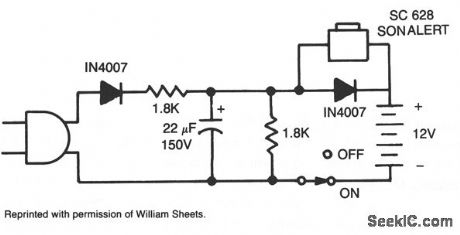
With power ac off, the alarm sounds when S1 is closed on. The 12-V battery is kept charged when the circuit is plugged in and the switch is left on. (View)
View full Circuit Diagram | Comments | Reading(0)
| Pages:7/18 123456789101112131415161718 |
Circuit Categories
power supply circuit
Amplifier Circuit
Basic Circuit
LED and Light Circuit
Sensor Circuit
Signal Processing
Electrical Equipment Circuit
Control Circuit
Remote Control Circuit
A/D-D/A Converter Circuit
Audio Circuit
Measuring and Test Circuit
Communication Circuit
Computer-Related Circuit
555 Circuit
Automotive Circuit
Repairing Circuit