
Alarm Control
Index 12
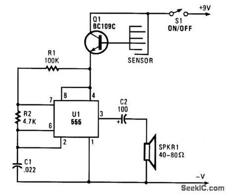
WATER_LEVEL_ALARM
Published:2009/6/25 2:49:00 Author:May
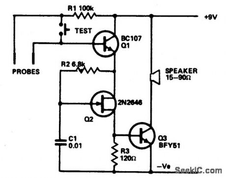
The circuit draws so little current that theshelf-line of the battery is the limiting factor.The only current drawn is the leakage of the transistor. The circuit is shown in the form of awater level alarm but by using different forms of probe can act as a rain alarm or shorting ween the probes will trigger it. Q1 acts as a switch which applies current to the unijunction relaxation oscillator Q2. Alarm signal frequency is controlled by values and ratios of C1/R2. Pulses switch Q3 on and off, applying a signal to the speaker. Almost any NPN silicon transistor can be used for Q1 and Q3 and almost any unijunction for Q2. (View)
View full Circuit Diagram | Comments | Reading(120)
HIGH_LOW_LIMIT_ALARM
Published:2009/6/25 1:38:00 Author:May
View full Circuit Diagram | Comments | Reading(0)
CAPACITANCE_OPERATED_ALARM_TO_FOIL_PURSE_SNATCHERS
Published:2009/6/24 23:01:00 Author:May
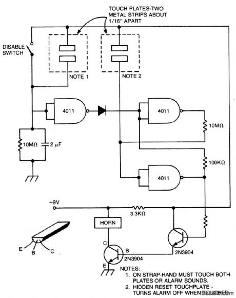
Aslong as touch plates (1) are touched together,the alarm is off. If not held for about 30 seconds,the alarm goes off. The circuit can be disabled with switch or by touching the plates (2),The alarm is battery operated by a bicycle horn. (View)
View full Circuit Diagram | Comments | Reading(0)
INDICATOR_AND_ALARM
Published:2009/6/24 21:24:00 Author:May
View full Circuit Diagram | Comments | Reading(989)
PROXIMITY_ALARM
Published:2009/6/24 21:10:00 Author:May
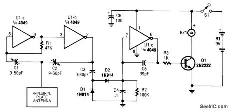
View full Circuit Diagram | Comments | Reading(0)
LATCHING_RELAY_ALARM_CIRCUIT
Published:2009/6/24 5:30:00 Author:May
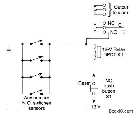
Momentarily closing any sensors will cause K1 to latch. S1 must be depressed to reset circuit. If any sensor is still closed circuit will not reset. (View)
View full Circuit Diagram | Comments | Reading(1406)
ALARM_CLOCK_TIMER
Published:2009/6/24 4:34:00 Author:May

Turn your alarm clock into a specialized timer with this simple circuit. The clock used with the circuit should be the kind that turns on a little lamp when the alarm is activated. (View)
View full Circuit Diagram | Comments | Reading(0)
HIGH_SPEED_WARNING_DEVICE
Published:2009/6/24 4:11:00 Author:May
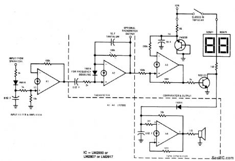
Al amplifies and regulates the signal from the spark coil. A2 converts frequency to vol-tage so that its output is a voltage proportional to engine rpm. A3 compares the tachometer voltage with the reference voltage and turns on the output transistor at the set speed. Amplifier A4 is used to generate an audible tone whenever the set speed is exceeded. (View)
View full Circuit Diagram | Comments | Reading(1461)
SPEED_ALARM
Published:2009/6/24 4:00:00 Author:May
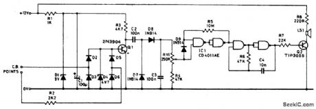
Pulses from the distributor points are pas-sed through a current limiting resistor, rec-tified, and clipped at 4.7 volts. Via Q1 and the diode pump, a dc voltage proportional to engine rpm is presented to RV1; the sharp transfer characteristic of a CM0S gate, assisted by feedback, is used to enable the oscillator formed by the remaining half of the 4011. At the pre-set speed, a nonignorable tone emits from the speaker, and disappears as soon as the speed drops by three or four mph. (View)
View full Circuit Diagram | Comments | Reading(1014)
The gas overranging alarm miner lamp 1
Published:2011/7/29 2:57:00 Author:Ecco | Keyword: gas overranging , alarm , miner lamp

The gas overranging alarm miner lamp described in the example is suitable for the environment with explosion gas in coal mine, the miners carry the device for lighting and detecting methane gas. When the methane gas is overlimit, the alarm signal will flash in time to remind miners to evacuate in time.
The working principle:The gas overranging alarm miner lamp circuit is composed of detection amplifier circuit and alarm circuit. It's shown as the figure 8-29.
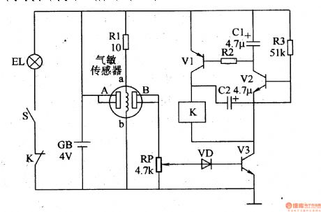
The detection amplifier circuit is composed of sensor, resistors Rl-Rl5, potentiometer RP, transistors Vl-V7 and voltage regulator diode VS. The alarm circuit consists of resistors R16-Rl8, capacitors Cl-C4, transistors V8 and V9, Diodes VDl and VD2, the relay K and miner's lamp EL.Turning on the power switch S (Sl, S2), EL is lit, the entire circuit gets power supply. The end of the sensor detects methane gas, the internal resistance of pure white carrier elements B and black catalytic elements A in sensor keep stable, V6 and V7 is off, the oscillator composed of V8, V9, and Cl-C4, R16-R18, K , VDl stops vibrating, K is in releasing state, EL in normal lighting condition.
(View)
View full Circuit Diagram | Comments | Reading(712)
The gas overranging alarm miner lamp 2
Published:2011/7/29 2:58:00 Author:Ecco | Keyword: gas overranging, alarm, miners lamp
The gas overranging alarm miner lamp described in the example is based on miner's lamp or miner's helmet. It couldflash in time to remind miners paying attention on safety.
The working principle: The gas overranging alarm miner lamp circuit is composed of gasdetection circuit, controlled oscillator circuit and lighting circuit. It's shown as the figure 8-30.
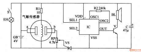
The gas detection circuit is composed of gas sensor, resistors Rl and potentiometer RP. The controlled oscillator circuit is composed of the potentiometer RP, a diode VD, transistors Vl-V3, resistor R2 and R3, capacitor Cl and C2 and the relay K. The lighting circuit is composed of the battery GB, lights EL, the constant moving contact of S and K light switch. The switch S turns off, EL will be lit. The end of the gas sensor detects methane gas, the place between A and B shows the state with high resistance, VD and V3 are in the OFF state, K is not action, miner working in the lighting condition.
(View)
View full Circuit Diagram | Comments | Reading(772)
The gas overranging alarm miner lamp 3
Published:2011/7/29 2:59:00 Author:Ecco | Keyword: gas overranging , alarm, miners lamp
The gas overranging alarm miner lamp described in the example uses the batteries of miner's lamp as power supply. It is installed in the mine cap.When the gas is over the limit, the alarm signal will remind miners to evacuate in time.
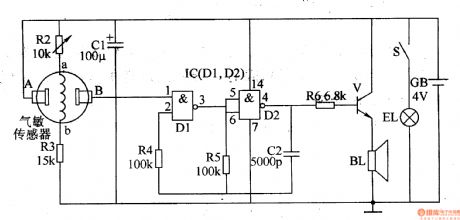
The working principle: The gas overranging alarm miner lamp circuit is composed of gas detection circuit,electronic switching circuit and sound alarm circuit. It's shown as the figure 8-31.
The gas detection circuit is composed of resistor Rl, and the gas sensor, potentiometer RP.
The electronic switching circuit is composed of thyristor VT and RP.
Thesound alarm circuit is composed of sound IC, resistor R2, transistor Vand speaker BL.
When the gas concentration is below the limit of safety standards, the conductivity between a and b of gas sensor is low, b point is in low level, VT is in the cut-off state, and IC does not work, BL does not sound.
When the gas concentration is over the limit of safety standards, the conductivity between a and b of gas sensor will increase, the voltage of b point increases, VT turns on by trigger, and IC works, the audio output signal amplified by the V will drive the alarm BL.
(View)
View full Circuit Diagram | Comments | Reading(629)
The gas overranging alarm miner lamp 4
Published:2011/7/29 2:59:00 Author:Ecco | Keyword: gas overranging, alarm , miners lamp
The working principle: The gas overranging alarm miner lamp circuit is composed of gas detection circuit, multivibrator, audio output circuit and lighting circuit. It's shown as the figure 8-32.
Gas detection circuitis composed ofthe gas sensor and resistors R2, R3.
Multivibrator is composed oftwo NAND gates Dl, D2 of internal NAND gate and resistors R4 and R5, capacitor C2.
Audio output circuit consists of resistors R6, audio amplification V and speaker BL.
Lighting circuit is composed of the battery GB, lights EL andK light switch.
When the indoor concentration of combustible gasis inthe allowable range (less than limit value), the resistance between the gas sensors A, B is high,the foot voltage of Ic is low, multivibrator does not work, the speaker BL has no sound. When the indoor concentration of combustible gasis over the limit, the resistance between the gas sensors A, B declines,the foot voltage of Ic is higher than conversion voltage of D1, multivibrator works,the output oscillation signal frompin 4of IC. The signal amplified by the V will promote the speaker BL.
(View)
View full Circuit Diagram | Comments | Reading(1305)
SIMPLE_FLOOD_ALARM
Published:2009/6/23 3:43:00 Author:May
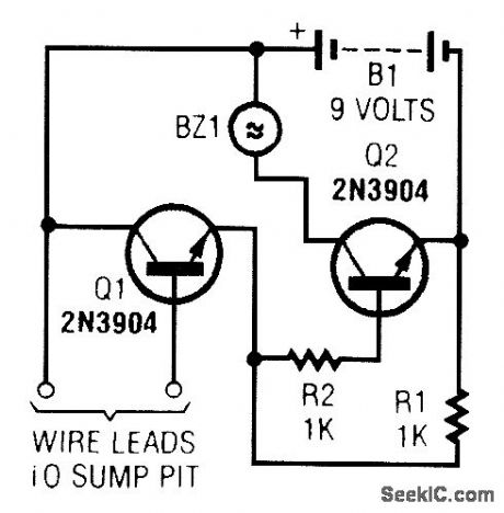
A common collector amplifier drives a 2N3904 switch to sound alarm BZ1. The wire leads to wa-ter sensor or surnp pit, level switch, etc. and used to allow the alarm to operate and be mounted in a dry place. (View)
View full Circuit Diagram | Comments | Reading(0)
WATER_ACTIVATED_ALARM
Published:2009/6/23 3:42:00 Author:May
When sensor gets wet, it conducts, forward-biases Q1, and activates audio oscillator U1. A tone is heard from the speaker. (View)
View full Circuit Diagram | Comments | Reading(0)
Photosensitive anti-theft alarm circuit diagram
Published:2011/5/17 3:36:00 Author:Ecco | Keyword: Photosensitive , anti-theft, alarm
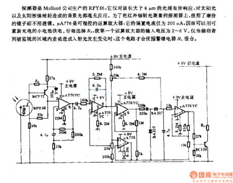
Detector is PRY86 produced by Mullard PRY86, it only responses to wavelengths whcih is greater than 6μm, and it has no reaction on background light caused by continued exposure of sunlight. In order to gather infrared light onto the detector, the inexpensive mirrors replace lenses. μA776 is a programmable operational amplifier, and its bias current is only 300μA, which can be recharged by a small battery. Careful selection of Ra could make the the input voltage of the first operational amplifier be 2 ~ 6V. Only if when the theft walksin the area being monitoredandit will causethe changing of incident light, then this circuit will make the alarm relay RL pull in.
(View)
View full Circuit Diagram | Comments | Reading(862)
Infrared anti-theft alarm circuit diagram
Published:2011/5/17 3:44:00 Author:Ecco | Keyword: Infrared, anti-theft , alarm circuit
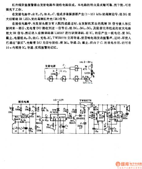
Infrared anti-theft alarm is composed of the radiating circuit and receiving circuit. This circuit is sensitive and reliable, anti-interference, it can work in bright light.
In radiating circuit, the multivibrator composed of F1, F2, and R1, C1 can produce 1 ~ 15KHz high frequency signal. After amplified by the BG, itdrives IR LED,emits a high-frequency infrared light (IR) signal.
In the receiving circuit, when there's someone passing or stopping in front of the launch head, the part of high-frequency IR signal from the transmitter will be reflected back by boby. DU photocell receives the signal, then it is amplifiered by the amplifier circuit composed of BG1, BG2, BG3 and RC components. And then it is decoded by the audio decoder LM567 and it produces low level on pin 8 of IC1 to stop BG1. Power charges for C1 by R1D1, ICdTWH8778 isimmediately turned onto make an alarm sound. At this time, even if the person has passed the restricted area , photodiode DU has no turn signal reception to make BG4, D1 cut off.
(View)
View full Circuit Diagram | Comments | Reading(1035)
FREEZER_MELTDOWN_ALARM
Published:2009/6/23 1:29:00 Author:May
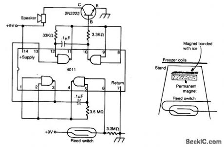
The meltdown is a magnet held to a small stand by ice. A reed switch is below the magnet. When the ice melts, the magnet falls on the switch, closing it, and completing the alarm circuit. (View)
View full Circuit Diagram | Comments | Reading(764)
SUN_POWERED_ALARM
Published:2009/6/23 1:29:00 Author:May
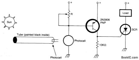
Circuit turns on when light (sunlight) strikes photocell. Potentiometer R sets light level at which the alarm sounds. Painted tube (black on inside) may be used on photocell to aim at the sun. (View)
View full Circuit Diagram | Comments | Reading(871)
LATCHING_BURGLAR_ALARM_1
Published:2009/6/22 23:58:00 Author:May
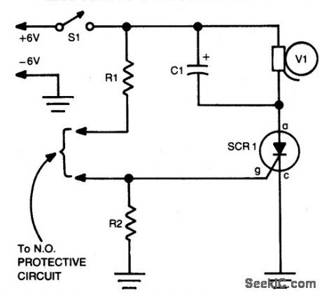
Closing the Protective circuit(i.e.,R1 to R2) applies positive voltage to the gate ofSCR1 and sounds the alapy). It can only be turned of with S1. (View)
View full Circuit Diagram | Comments | Reading(900)
| Pages:12/18 123456789101112131415161718 |
Circuit Categories
power supply circuit
Amplifier Circuit
Basic Circuit
LED and Light Circuit
Sensor Circuit
Signal Processing
Electrical Equipment Circuit
Control Circuit
Remote Control Circuit
A/D-D/A Converter Circuit
Audio Circuit
Measuring and Test Circuit
Communication Circuit
Computer-Related Circuit
555 Circuit
Automotive Circuit
Repairing Circuit