
Alarm Control
Index 13
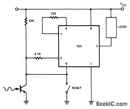
BURGLAR_ALARM
Published:2009/6/22 23:55:00 Author:May
View full Circuit Diagram | Comments | Reading(1368)
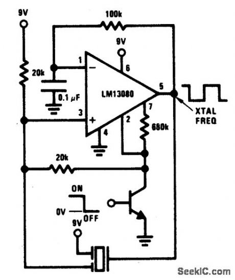
PIEZOELECTRIC_ALARM
Published:2009/6/22 23:54:00 Author:May
View full Circuit Diagram | Comments | Reading(0)
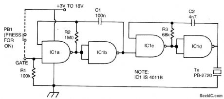
PULSED_TONE_ALARM,GATED_BY_A_HIGH_INPUT,WITH_DIRECT_DRIVE_OUTPUT
Published:2009/6/22 23:53:00 Author:May
View full Circuit Diagram | Comments | Reading(0)
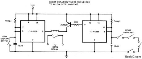
AUTO_BURGLAR_ALARM_1
Published:2009/6/22 23:50:00 Author:May
View full Circuit Diagram | Comments | Reading(0)
BLOWN_FUSE_ALARM
Published:2009/6/22 23:49:00 Author:May
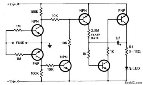
If the fuse blows, the LED indicator starts to blink. (View)
View full Circuit Diagram | Comments | Reading(0)
BOAT_ALARM
Published:2009/6/22 23:48:00 Author:May

Removing R1 or R2 from the circuit (i.e., the potentiai thief breaks a hidden wire that connects R1 to +12 V and R2 to ground) activates the alarm for about five minutes. (View)
View full Circuit Diagram | Comments | Reading(829)
LATCHING_BURGLAR_ALARM
Published:2009/6/22 23:46:00 Author:May
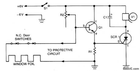
When the protective circuit is interrupted (opened), the alarm sounds. To set the circuit, adjust R2 (with protective circuit open) for 1 V across R1. (View)
View full Circuit Diagram | Comments | Reading(1095)
SECURITY_ALARM
Published:2009/6/22 23:38:00 Author:May

This alarm features open- and closed-loop detector and automatic alarm shutoff. Offers 15 second exit/entrance delay. Alarm on time can be adjusted from 1 to 15 minutes. (View)
View full Circuit Diagram | Comments | Reading(0)
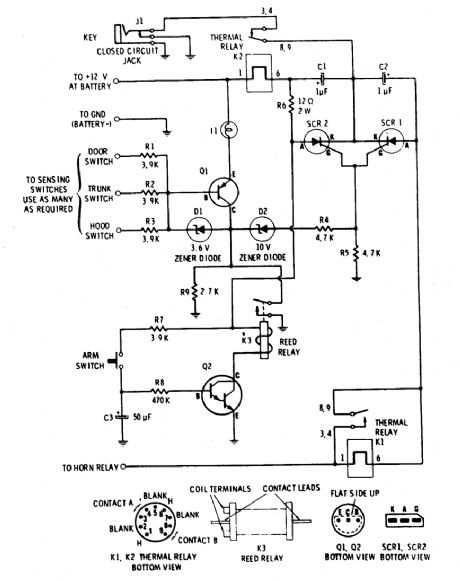
AUTOMOTIVE_BURGLAR_ALARM
Published:2009/6/22 23:35:00 Author:May
Alarm triggers on after a 13 second delay and stays on for 1-1 1/2 minutes. Then it resets automatically. It can also be turned off and reset by opening and reclosing S1. (View)
View full Circuit Diagram | Comments | Reading(0)
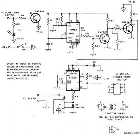
COMPUTALARM
Published:2009/6/22 23:25:00 Author:May
The circuit has a built-in, self-arming feature. The driver turns off the ignition, presses the arm button on the Computalarm, and leaves the car. Within 20 seconds, the alarm arms itself-all automatically! The circuit will then detect the opening of any monitored door, the trunk lid, or the hood on the car. Once acti-vated, the circuit remains dormant for 10 sec-onds. When the 10-second time delay has run out, the circuit will close the car's horn relay and sound the ham in periodic blasts (approxi-mately 1 to 2 seconds apart) for a period of one minute. Then the Computalarm automatically shuts itself off (to save your battery) and re-arms. If a door, the trunk lid, or the hood re-mains ajar, the alarm circuit retriggers and another period of horn blasts occurs. The Com-putalarm has a key switch by which the driver can disarm the alarm circuit within a 10-second period after he enters the door. The key switch consists of a closed circuit jack, J1, and a mating miniature plug. (View)
View full Circuit Diagram | Comments | Reading(0)
ALARM_DIALER
Published:2009/6/22 22:48:00 Author:May

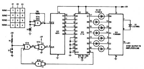
This circuit dials a stored DTMF tone sequence from EPROM when a control line is taken to 0 V. IC1 is a Schmitt trigger oscillator, running at around 2 Hz. It clocks a 4024 binary counter. The coun-ter's outputs connect to the address leads of the EPROM. A 2716 was used here, but the choice of EPROM is by no means critical.Normally, the counter is held reset by a logic 1 on its reset pin (pin 2). When the trigger input is sent low, pin 10 of IC1 goes low, pin 3 goes high, and the reset is removed from the counter. It then begins to clock, incrementing the EPROM. When moved from address 000000, the data on bit DO of the EPROM changes to a logic 1 and holds the circuit running. The last address should have data 11111110 to reset the circuit to standby. (View)
View full Circuit Diagram | Comments | Reading(0)
BACKUP_BATTERY_MONITOR_CHARGER_ALARM
Published:2009/6/19 2:59:00 Author:May


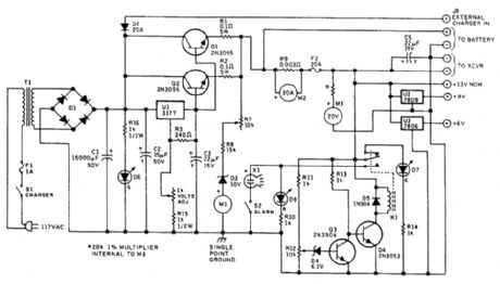
Battery Condition Meter Calibratio Lead-Acid Battery Lead Calcium RatteryColor Voltage Color VoltageRed 11.6 and below Red 11.6 and belowYellow 11.6 to 12.0 Yellow 11.6 to 12.0Green 12.0 to 13.8 Green 12.0 to 13.5Red 13.5 and higher Red 13.5 and higher
Charging voltage is constant at the normal full-charge level, so the charging current drops as full oharge is approached, and full charge is maintained with a trickle current. The charging voltage can be adjusted between approximately 10 and 15 Vdc to accommodate lead-acid (13.8 V) or lead-cal-ciurn (13.2V, 13.5V maximum) deep-cycle storage batteries.A separate connection is provided so that an extemal charger can be used when greater than 3 A is needed to charge a pa'rtially discharged battery. Intemal circuitry will maintain the charging volt-age to the battery at the nominal full-charge voltage level, regardless of the voltage supplied by the external charger, which will be 2V or more greater than that applied by the regulator to the storage battery. Warning: do not fast-charge deep-cycle storage batteries!A pair of meters calibrated to indicate 20 Vdc and 20 Adc full-scale monitor voltage and current when battery power is used.A separate, suppressed zero, expanded-scale meter calibrated over the range of about 10 to 15 Vdc allows immediate and constant indication of the state of charge of the station's backup battery.This meter scale is calibrated in bands of red, yellow, and green, as explained in the table. The nar-row yellow segment is based on the assurnption that solid-state transceivers might not operate prop-erly below +12 Vdc. The intemal power supply is used to calibrate this meter. A DMM should be used for greatest accuracy.An alarm circuit is included to indicate when the battery has been discharged by 60 percent tothe 11.6-Vdc level When battery voltage IS above 11.6 V, the green LED will be illuminated;when voltage falls to 11.6V, the green LED goes out and the red LED lights A piezo audible alarm soundsat this low voltage level unless silenced by the toggle switch controlling it.A pair offixed three-terminal regulators are included to provide+9 and+6 Vdc (View)
View full Circuit Diagram | Comments | Reading(1857)
TURN_SIGNAL_ALARM
Published:2009/6/19 2:25:00 Author:May
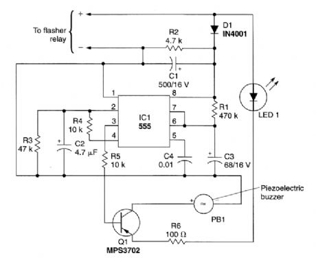
This circuit can be used to tell the driver of a vehicle when his or her turn signal has been left on for too long. The circuit consists of IC1, a 555 timer; transistor Q1, and MPS3702 PNP preamp/driver; PB1, a piezoelectric buzzer; along with an assortment of resistors, capacitors, and diodes. The 555 is connected in the mono.stable mode, requiring only a momentary negative pulse at pin 2 to trigger the timing cycle.Power for the circuit is picked off the flasher relay and applied to IC1, pin 8, provided by an ini-tially discharged capacitor, C2. After the initial triggering, the voltage across C2 rises as it becomes charged through R4, a 10-kΩ resistor. This prevents subsequent interference with the delay function caused by false triggering.Capacitor C3 and resistor R1 determine the delay. With the component values shown, a delay of about one minute will be provided before the intermittent tweet sound generated by the circuit be-gins. If higher values are used for C2 and R1, a longer delay time will result. The light-emitting diode, LED1, provides a voltage drop to assure complete transistor blocking during the off periods of the flasher. Alternatively, two diodes in series can be used. (View)
View full Circuit Diagram | Comments | Reading(1801)
DUAL_CLOCK_CIRCUIT_FOR_STEPPER_MOTORS
Published:2009/6/18 23:41:00 Author:May
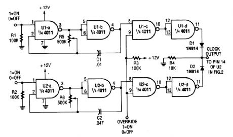
This oscillator can be used to drive a stepper motor circuit at two preset speeds with override to shut the motors off. (View)
View full Circuit Diagram | Comments | Reading(894)
ALTERNATE_TONE_ALARM
Published:2009/6/18 23:23:00 Author:May
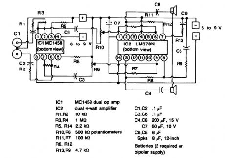
A two-tone generator that is alternately switched ON provides a high/low output as might be heard from a traffic vehicle like a police car or ambulance.IC1, CD4011, quad 2-input NAND gate is a two-tone oscillator in which each side, pins 1 through 7 and 8 through 13 set the tone frequencies. Changing the values of C2 and C1 determines the high/low tones. The outout frequencies are coupled to IC2, CD4011, of which one side (pins 1 through 6) acts as a buffer. The buffer is necessary to prevent loading on the outputs that would occur if one tried to go directly to the LM386 amplifier. The other side of IC2, pins 8 through 13, is a slow pulse osciLator of approximately 8 Hz per second. The output at pin 10 is bonnected to IC4 as a clock.IC4, CD4027, is a dual J-K master-slave flip-flop that is wired to perform as a toggle switch in which Q1 and 15, and Q1 (NOT) pin 14, go high and low alternately (flip-flop). The clock input from IC2 pin 10 is connected to pin 13 of IC4, and the outputs at pins 15 and 14 changes the flip/flop state with each positive pulse transition. The CD4027 functions in toggle mode when the set and reset inputs, pins 9 and 12, are held low or grounded. Also, J-K inputs, pins 10 and 11, must be held high or to the positive.The outputs Q1 and Q1 (NOT), pins 15 and 14 are connected to pins 13 and 1 respectively oflC1 that enables or disables. Thus, each tone oscillator is turned on and off alternately. IC3 is a straightforward low-voltage audio amplifier. (View)
View full Circuit Diagram | Comments | Reading(1780)
SIREN
Published:2009/6/18 23:12:00 Author:May
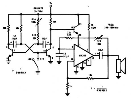
An LM380 audio IC is configured as a feed-transistor astable modu-a low frequency, which back audio oscillator. A lates this oscillator at a low frequency, which produces a siren tone. (View)
View full Circuit Diagram | Comments | Reading(2)
SPACESHIP_ALARM
Published:2009/6/18 22:51:00 Author:May
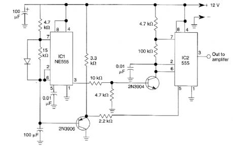
By using two 555 timers this circuit produces a low frequency tone that rises to a high frequency tone in a little over 1 second. Then the sound stops for about 0.3 seconds, thereafter the cycle re-peats. To produce the alarm sound of the Star Trek spaceship. (View)
View full Circuit Diagram | Comments | Reading(1033)
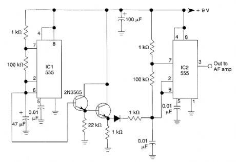
1000_Hz_PULSED_TONE_ALARM
Published:2009/6/18 22:48:00 Author:May
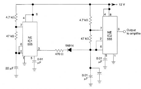
IC1 generates a pulse that modulates the 1000-Hz tone generated by IC2. This circuit can be used to generate warning or alert signals. (View)
View full Circuit Diagram | Comments | Reading(816)
SIREN_ALARM
Published:2009/6/18 22:48:00 Author:May
The ramp voltage from the low frequency oscillator IC1 modulates IC2 thereby producing a rising and falling tone like the siren wail of police cars. (View)
View full Circuit Diagram | Comments | Reading(991)
HORN_CIRCUIT_FOR_MOTORCYCLE_USE
Published:2009/6/18 2:02:00 Author:May
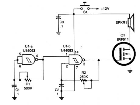
Gates U1-a and U1-b of the 4093 quad 2-tnput NAND Schmitt trigger are connected in variable, low-frequency, square-wave oscillator circuits. The output of gate U1-a is connected to one of the inputs of gate U1-b. The square-wave output of gate U1-a modulates oscillator U1-b, producing a two-tone output. A really interesting sound can be producecl by carefully adjusting po-tentiometers R1 and R2. (View)
View full Circuit Diagram | Comments | Reading(3658)
| Pages:13/18 123456789101112131415161718 |
Circuit Categories
power supply circuit
Amplifier Circuit
Basic Circuit
LED and Light Circuit
Sensor Circuit
Signal Processing
Electrical Equipment Circuit
Control Circuit
Remote Control Circuit
A/D-D/A Converter Circuit
Audio Circuit
Measuring and Test Circuit
Communication Circuit
Computer-Related Circuit
555 Circuit
Automotive Circuit
Repairing Circuit