
Control Circuit
Index 161
DIGITALLY_CONTROLLED_ASTABLE_M_ULTIVIBRATOR
Published:2009/6/26 2:00:00 Author:May
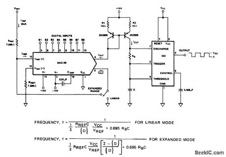
View full Circuit Diagram | Comments | Reading(533)
POWER_TOOL_TORQUE_CONTROL
Published:2009/6/26 1:51:00 Author:May
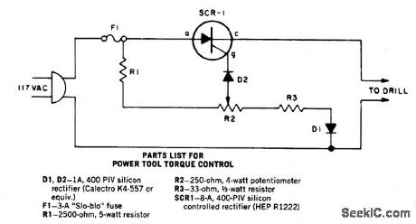
As the speed of an electric drill is decreased by loading, its torque also drops. A compensating speed control like this one puts the oomph back into the motor. When the drill slows down, a back voltage developed across the motor-in series with the SCR cathode and gate-decreases. The SCR gate voltage therefore increases relatively as the back voltage is reduced. The extra gate voltage causes the SCR to conduct over a larger angle and more current is driven into the drill, even as speed falls under load. The SCR should be mounted in 1/4-in. thick block of aluminum or copper at least 1-in. square. If the circuit is used for extended periods use a 2 inch square piece. (View)
View full Circuit Diagram | Comments | Reading(3549)
DIRECTION_AND_SPEED_CONTROL_FOR_SHUNT_WOUND_MOTORS
Published:2009/6/26 1:47:00 Author:May
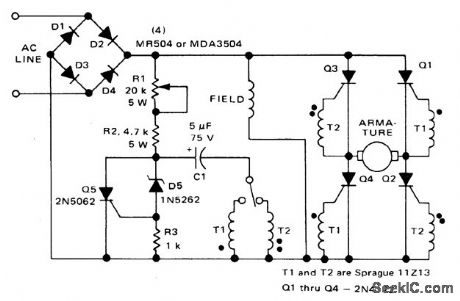
This circuit operates like the one shown in Fig. 57-4. The only differences are that the field is placed across the rectified supply and the armature is placed in the SCR bridge. Thus the field current is unidirectional but armature current is reversible; consequently the motor's direction of rotation is reversible. Potentiometer R1 controls the speed. (View)
View full Circuit Diagram | Comments | Reading(1)
SPEED_CONTROL_FOR_MODEL_TRAINS_OR_CARS
Published:2009/6/26 1:46:00 Author:May
Low voltage speed control gives very good starting torque and excellent speed regulation. A reversing switch may be incorporated in the leads to the motor. (View)
View full Circuit Diagram | Comments | Reading(709)
UNIVERSAL_MOTOR_CONTROL_WITH_BUILT_IN_SELF_TIMER
Published:2009/6/26 1:45:00 Author:May
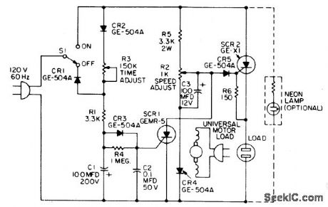
When the time delay expires, SCR1 conducts and removes the gate signal from SCR2, which stops the motor. Both the time delay and motor speed are adjustable by potentiometers R2 and R3. If heavier motor loads are anticipated, use the larger C30B SCR in place of the GE-X1 for SCR2. Also, the capacitance of C1 can be increased to lengthen the tinie delay, if desired. (View)
View full Circuit Diagram | Comments | Reading(1622)
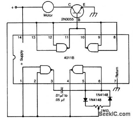
1DC_MOTOR_SPEED_CONTROL
Published:2009/6/26 1:43:00 Author:May

The circuit uses a 4011 CM0S NAND gate, a pair of diodes and an NPN power transistor to provide a variable duty-cycle dc source. Adjusting the speed control varies the average voltage applied to the motor. The peak voltage, however, is not changed. This pulse power is effective at very low speeds, constantly kicking the motor along. At higher speeds, the motor behaves in a nearly normal manner. (View)
View full Circuit Diagram | Comments | Reading(874)
DIFFERENTIAL_THERMOMETER
Published:2009/6/26 1:43:00 Author:May
View full Circuit Diagram | Comments | Reading(0)
1INDUCTION_MOTOR_CONTROL
Published:2009/6/26 1:42:00 Author:May
This single time-constant circuit can be used as proportional speed control for induction motors such as shaded pole or permanent split-capacitor motors when the load is fixed. The circuit is best suited to applications which require speed control in the medium to fullpower range. (View)
View full Circuit Diagram | Comments | Reading(2132)
WIND_ACTIVATED_CONTROL
Published:2009/6/25 23:47:00 Author:May
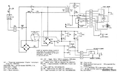
Anemometer feeding meter relay energizes control relay for antenna-tower hoist motor, to lower tower au-tomatically when wind exceeds preset safe speed and raise it again when wind drops well below danger level. When only K1 is energized, motor rotates in tower-lowering direction.When K1 and motor-reversing relay K2 are both energized, motor reverses and raises tower.-J.Bernstein, The Tower-Guard System, QST 1974,p 25-28 (View)
View full Circuit Diagram | Comments | Reading(1800)
DC_MOTOR_SPEED_CONTROL
Published:2009/6/25 23:47:00 Author:May
The circuit uses a 4011 CM0S NAND gate, a pair of diodes and an NPN power transistor to provide a variable duty-cycle dc source. Adjusting the speed control varies the average voltage applied to the motor. The peak voltage, however, is not changed. This pulse power is effective at very low speeds, constantly kicking the motor along. At higher speeds, the motor behaves in a nearly normal manner. (View)
View full Circuit Diagram | Comments | Reading(1981)
3_ANTENNA_REMOTE_SWITCHING
Published:2009/6/25 23:46:00 Author:May
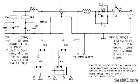
Single RF feed line serves for feeding transmitter power to tower and selecting desired one of three an-tennas. With S1 at a, neither K1 nor K2 is energized. RF energy then passes through cable to antenna terminals a' and GND. In position b,positive half-waves from 12-VAC supply operate relay K1 through CP1 and CR3, so antenna b' is energized. With S1 at c, K2 is energized through CR4 and CR2 forfeeding c'.-U. H. Lam-mers, A Remote Antenna Switch, QST, Aug.1974, p 41-43. (View)
View full Circuit Diagram | Comments | Reading(853)
INDUCTION_MOTOR_CONTROL
Published:2009/6/25 23:45:00 Author:May

This single time-constant circuit can be used as proportional speed control for induction motors such as shaded pole or permanent split-capacitor motors when the load is fixed. The circuit is best suited to applications which require speed control in the medium to fullpower range. (View)
View full Circuit Diagram | Comments | Reading(1811)
MODEL_TRAIN_SPEED_CONTROL
Published:2009/6/25 23:44:00 Author:May
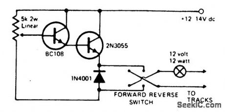
Virtually any NPN small signal transistor may be used in place of the BC 108 shown.Likewise any suitable NPN power transistor can be used in place of the 2N3055. The output transistor must be mounted on a suitable heat-sink. Short circuit protection may be provided by wiring a 12 volt 12 watt bulb in series with the output. This will glow in event of a short circuit and thus effectively current-limit the output, it also acts as a visual short-circuit alarm. (View)
View full Circuit Diagram | Comments | Reading(2270)
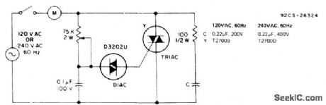
2MOTOR_SPEED_CONTROL
Published:2009/6/25 23:43:00 Author:May
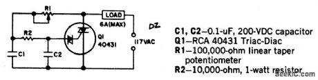
Universal motors and shaded-pole induction motors can be easily controlled with a full-wave Triac speed controller. Q1 combines both the triac and diac trigger diodes in the same case. The motor used for the load must be limited to 6 amperes maximum. Triac Q1 must be provided with a heat sink. With the component values shown, the Triac controls motor speed from full off to full on. (View)
View full Circuit Diagram | Comments | Reading(1651)
DC_MOTOR_SPEED/DIRECTION_CONTROL_CIRCUIT
Published:2009/6/25 23:41:00 Author:May
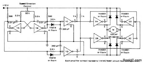
View full Circuit Diagram | Comments | Reading(774)
HIGH_SPEED_PEAK_DETECTOR
Published:2009/6/25 23:19:00 Author:May
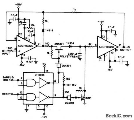
View full Circuit Diagram | Comments | Reading(859)
TEMPEATURE_CONTROLLER
Published:2009/6/25 23:18:00 Author:May
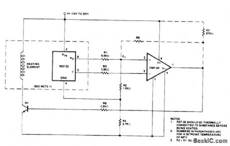
Temperature control is achieved using the REF-02 +5 V Reference/Thermometer and a CMP-02 Precision Low Input Current Com-parator. The CMP-02 turns on a heating ele-ment driver (Q1) whenever the present temperature drops below a setpoint temperature determined by the ratio of RI to R2. The circuit also provides adjustable hysteresis and single supply operation. (View)
View full Circuit Diagram | Comments | Reading(652)
TEMPERATURE_CONTROL
Published:2009/6/25 23:16:00 Author:May
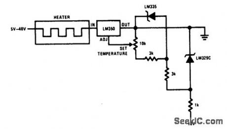
View full Circuit Diagram | Comments | Reading(1127)
UNIVERSAL_MOTOR_SPEED_CONTROL_WITH_LOAD_DEPENDENT_FEEDBACK(FOR_MIXER,SEWING_MACHINE,ETC)
Published:2009/6/25 23:40:00 Author:Jessie
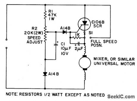
Simple half-wave motor speed control is effective for use with small universal (ac/dc) motors. Maximum current capability 2.0 amps RMS. Because speed-dependent feedback is provided, the control gives excellent torque characteristics to the motor, even at low rotational speeds. Normal operation at maximum speed can be achieved by closing switch S1, thus bypassing the SCR. (View)
View full Circuit Diagram | Comments | Reading(2508)
AC_MOTOR_BRAKE
Published:2009/6/25 23:37:00 Author:Jessie
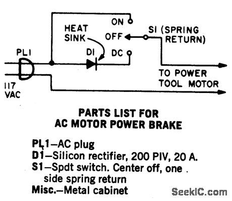
A shot of direct current will instantly stop any ac power tool motor. Switch S1 is a center-off, one side spring return. With S1 on, ac will be fed to the motor and the motor will run. To brake the motor, simply press S1 down and a quick shot of dc will instantly stop it. The switch returns to the center off position when released. This Power Brake can only be used with ac motors; it will not brake universal (ac-dc) motors. A heat sink must be provided for the diode. (View)
View full Circuit Diagram | Comments | Reading(1790)
| Pages:161/312 At 20161162163164165166167168169170171172173174175176177178179180Under 20 |
Circuit Categories
power supply circuit
Amplifier Circuit
Basic Circuit
LED and Light Circuit
Sensor Circuit
Signal Processing
Electrical Equipment Circuit
Control Circuit
Remote Control Circuit
A/D-D/A Converter Circuit
Audio Circuit
Measuring and Test Circuit
Communication Circuit
Computer-Related Circuit
555 Circuit
Automotive Circuit
Repairing Circuit