
Control Circuit
Index 175
Photosensitive anti-theft alarm circuit diagram
Published:2011/5/17 3:36:00 Author:Ecco | Keyword: Photosensitive , anti-theft, alarm
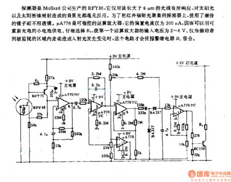
Detector is PRY86 produced by Mullard PRY86, it only responses to wavelengths whcih is greater than 6μm, and it has no reaction on background light caused by continued exposure of sunlight. In order to gather infrared light onto the detector, the inexpensive mirrors replace lenses. μA776 is a programmable operational amplifier, and its bias current is only 300μA, which can be recharged by a small battery. Careful selection of Ra could make the the input voltage of the first operational amplifier be 2 ~ 6V. Only if when the theft walksin the area being monitoredandit will causethe changing of incident light, then this circuit will make the alarm relay RL pull in.
(View)
View full Circuit Diagram | Comments | Reading(861)
Infrared anti-theft alarm circuit diagram
Published:2011/5/17 3:44:00 Author:Ecco | Keyword: Infrared, anti-theft , alarm circuit
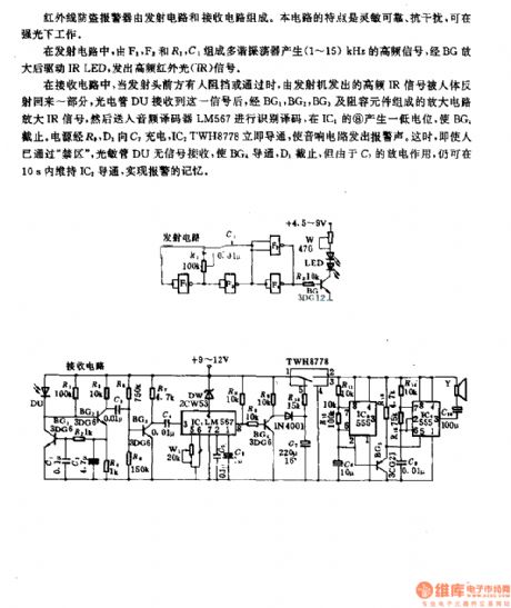
Infrared anti-theft alarm is composed of the radiating circuit and receiving circuit. This circuit is sensitive and reliable, anti-interference, it can work in bright light.
In radiating circuit, the multivibrator composed of F1, F2, and R1, C1 can produce 1 ~ 15KHz high frequency signal. After amplified by the BG, itdrives IR LED,emits a high-frequency infrared light (IR) signal.
In the receiving circuit, when there's someone passing or stopping in front of the launch head, the part of high-frequency IR signal from the transmitter will be reflected back by boby. DU photocell receives the signal, then it is amplifiered by the amplifier circuit composed of BG1, BG2, BG3 and RC components. And then it is decoded by the audio decoder LM567 and it produces low level on pin 8 of IC1 to stop BG1. Power charges for C1 by R1D1, ICdTWH8778 isimmediately turned onto make an alarm sound. At this time, even if the person has passed the restricted area , photodiode DU has no turn signal reception to make BG4, D1 cut off.
(View)
View full Circuit Diagram | Comments | Reading(1033)
TRIAC_LAMP_DIMMER_CIRCUIT
Published:2009/6/23 1:58:00 Author:May
The brightness of a lamp or lamps can be varied with this circuit. The snubber circuit values are typically 0.1 μF and 100-Ω.R8, is typically 25 to 100 kQ. (View)
View full Circuit Diagram | Comments | Reading(964)
AUTOMATIC_TTL_MORSE_CODE_KEYER
Published:2009/6/23 1:53:00 Author:May
Automatic'any generated dits and dahs are produced over a speed range of 11 to 39 wpm. The upper limit can be raised by decreasing R2. SW1 and SW2 can be a home, brew paddle operated key. (View)
View full Circuit Diagram | Comments | Reading(656)
AUTOMATIC_TAPE_RECORDING
Published:2009/6/23 1:42:00 Author:May
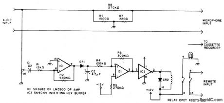
Amateurs don’t haveto missthe action while away from the tug.This circuit turns on a tape recorder whenever the recelver’s squelch IS broken. After signal loss, the recorder will shut off following a slight delay. (View)
View full Circuit Diagram | Comments | Reading(0)
FREEZER_MELTDOWN_ALARM
Published:2009/6/23 1:29:00 Author:May
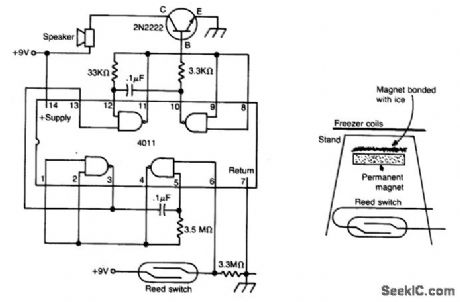
The meltdown is a magnet held to a small stand by ice. A reed switch is below the magnet. When the ice melts, the magnet falls on the switch, closing it, and completing the alarm circuit. (View)
View full Circuit Diagram | Comments | Reading(762)
Liquid level automatic controller circuit diagram 6
Published:2011/7/28 20:40:00 Author:Ecco | Keyword: Liquid level , automatic controller
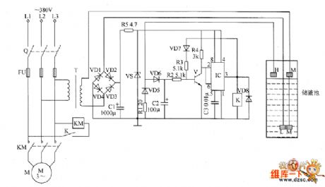
The liquid level automatic controller circuit is composed of the power supply circuit, level detection circuit and control implementation circuit, and the circuit is shown as the chart. Power supply circuit is composed of the knife switch Q, fuse FU, power transformer T, rectifier diodes VD1 ~ VD4, current limiting resistors R1 and R5, filter capacitor C1 and Zener diode VS. Level detection circuit is composed of the high-level electrode H, low-level electrode L and the main electrode M. Control implementation circuit is composed of the transistor V, relay K, time-base integrated circuit IC, diodes VD5 ~ VD8 and external RC components.
(View)
View full Circuit Diagram | Comments | Reading(1218)
SUN_POWERED_ALARM
Published:2009/6/23 1:29:00 Author:May
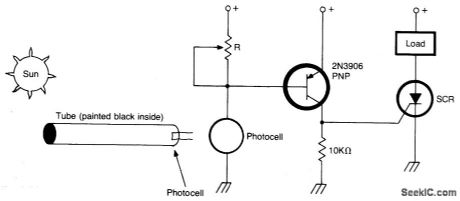
Circuit turns on when light (sunlight) strikes photocell. Potentiometer R sets light level at which the alarm sounds. Painted tube (black on inside) may be used on photocell to aim at the sun. (View)
View full Circuit Diagram | Comments | Reading(869)
Temperature controller circuit diagram 2
Published:2011/7/28 21:37:00 Author:Ecco | Keyword: Temperature controller
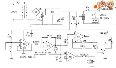
The temperature controller circuit is composed of the power supply circuit, temperature detection circuit, reference voltage circuit, temperature indicator circuit, voltage comparator amplifier and control implementation circuit, and it is shown as the chart. Power supply circuit is composed of the power switch S, power transformer T, bridge rectifier UR, filter capacitors C1, C2, three-terminal voltage regulator integrated circuit IC2, current limiting resistor RIO and power indicator LED VL1. Temperature detection circuit consists of the transistor temperature sensor V1, resistor R1, capacitor C3 and N1 which is inside of the operational amplifier integrated circuit IC1 (N1 ~ N4).
(View)
View full Circuit Diagram | Comments | Reading(1577)
Temperature controller circuit diagram 5
Published:2011/7/28 21:46:00 Author:Ecco | Keyword: Temperature controller
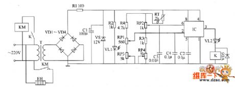
The temperature control circuit is composed of the power supply circuit, temperature detection control circuit and control implementation circuit, and it is shown as the chart. Power supply circuit is composed of the power transformer T, rectifier diodes VD1 ~ VD4, resistors R1 and R2, power indicator LED VL1, filter capacitor C1 and Zener VS and so on. Temperature detection control circuit consists of thermistor RT, time-base integrated circuit IC, potentiometers RP1 ~ RP4, resistor R3 and capacitors C2 ~ C4. Control implementation circuit is composed of the relay K1, LED VL2, diode VD5, AC contactor KM and electric heater EH.
(View)
View full Circuit Diagram | Comments | Reading(992)
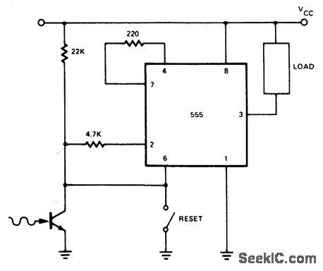
LATCHING_BURGLAR_ALARM_1
Published:2009/6/22 23:58:00 Author:May
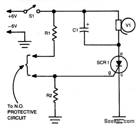
Closing the Protective circuit(i.e.,R1 to R2) applies positive voltage to the gate ofSCR1 and sounds the alapy). It can only be turned of with S1. (View)
View full Circuit Diagram | Comments | Reading(899)
Temperature controller circuit diagram 3
Published:2011/7/28 21:41:00 Author:Ecco | Keyword: Temperature controller
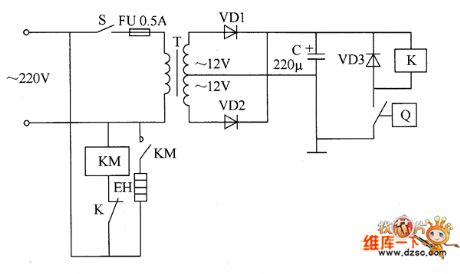
The temperature controller circuit is composed of the power supply circuit and temperature detection control circuit, and it is shown as the chart. Power supply circuit is composed of the power switch S, fuse FU, power transformer T, rectifier diodes VD1, VD2 and filter capacitor C. Temperature detection control circuit is composed of electric contact thermometer Q, relay K, AC contactor KM, diode VD3 and electric heater EH. C selects the aluminum electrolytic capacitor with the voltage in 25V. VD1 ~ VD3 select the 1 N4007 silicon rectifier diodes. K selects the JRX-13F orJQX-4F 12V DC relay.
(View)
View full Circuit Diagram | Comments | Reading(723)
BURGLAR_ALARM
Published:2009/6/22 23:55:00 Author:May
View full Circuit Diagram | Comments | Reading(1367)
PIEZOELECTRIC_ALARM
Published:2009/6/22 23:54:00 Author:May
View full Circuit Diagram | Comments | Reading(0)
SWR_WARNING_INDICATOR
Published:2009/6/23 1:47:00 Author:Jessie
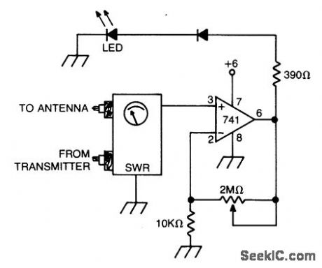
Op amp with dc input from SWR metercan be adjusted to preset the SWR reading at which the LED lights. (View)
View full Circuit Diagram | Comments | Reading(0)
MC33035 over-current protection circuit diagram
Published:2011/7/28 21:32:00 Author:Ecco | Keyword: over-current protection circuit
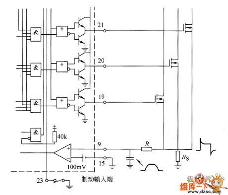
MC33035 overcurrent protection circuit is shown as the chart. MC33035 uses the external inverter to be grounded by resistor RS for the current sampling. Sampling voltage is input to the current sense comparator by pin 9 and pin 15. Inverting input of the comparator (pin 15) is set a 100mV reference voltage, which is used as the current limit ing benchmark. In the oscillator sawtooth rising time, if the current is too large, the comparator will flip so that the next RS flip-flop resets and closes the driven output to limit the current from continuing increase.
(View)
View full Circuit Diagram | Comments | Reading(1583)
Temperature controller circuit diagram 4
Published:2011/7/28 21:44:00 Author:Ecco | Keyword: Temperature controller
The temperature controller circuit is composed of the power supply circuit, temperature detection control circuit and control implementation circuit, and it is shown as the chart. Power supply circuit is composed of the power switch s, power transformer T, bridge rectifier UR, filter capacitors C1 ~ C3, three-terminal voltage regulator integrated circuit IC1, resistor R2 and power indicator LED VL1. Temperature detection control circuit is composed of the temperature detection diode VD1, resistors R3 ~ R1O, operational amplifier integrated circuit IC2 (N1 ~ N3) and the potentiometer RP. R1 ~ R12 select the 1/4W metal film resistors. RP uses a linear potentiometer. C1 selects the aluminum electrolytic capacitor with voltage in 25V.
(View)
View full Circuit Diagram | Comments | Reading(961)
OUTPUT_TO_CURRENT_CONVERTER
Published:2009/6/23 1:44:00 Author:Jessie
Occasionally, it is preferable to generate a cur-rent, rather than a voltage, output into the load.The availability of differential inputs aJlows this to be accomplished in any of the four basic modes.If the output is to integrated, ZL can be sim-ple high-quality capacitor, unloaded by an op amp connected as a high-impedance follower.Note that, if desired, one side of a rest switch can be grounded.The compliance constraint for this configura-tion, where VL is an arbitrary common-mode po-tential, is: |VL+IOUT(ZL+RS)|≤12V (View)
View full Circuit Diagram | Comments | Reading(1510)
CURRENT_TO_VOLTAGE_CONVERTER_FOR_GROUNDED_LOADS
Published:2009/6/23 1:42:00 Author:Jessie
This circuit uses an Analog Devices AD830 video difference amplifier. The circuit consists of two differential inputs. Unlike a conventional op amp, the AD830's output is nulled when the sum of the differences of the two inputs is zero.The AD830's stated unity-gain bandwidth is 60 MHz, and the device is capable of driving up to ±30 mA directly. The differential input voltage is limited to ±2V, while the maximum power supply is ±15 V.If more output current is desired, the AD830 can drive a bipolar transistor (such as an MJE200) directly. This will produce a one-sided output.A ferrite bead can be placed on the base to prevent oscillation under some conditions. Com-pensation can be added by splitting RS, and adding a variable capacitor. A resistor can be po-sitioned at the input to match the amplifier's in-put to a transmission line. (View)
View full Circuit Diagram | Comments | Reading(1716)
PULSED_TONE_ALARM,GATED_BY_A_HIGH_INPUT,WITH_DIRECT_DRIVE_OUTPUT
Published:2009/6/22 23:53:00 Author:May
View full Circuit Diagram | Comments | Reading(0)
| Pages:175/312 At 20161162163164165166167168169170171172173174175176177178179180Under 20 |
Circuit Categories
power supply circuit
Amplifier Circuit
Basic Circuit
LED and Light Circuit
Sensor Circuit
Signal Processing
Electrical Equipment Circuit
Control Circuit
Remote Control Circuit
A/D-D/A Converter Circuit
Audio Circuit
Measuring and Test Circuit
Communication Circuit
Computer-Related Circuit
555 Circuit
Automotive Circuit
Repairing Circuit