
Control Circuit
Index 165
BATTERY_LANTERN_CIRCUIT_
Published:2009/6/25 2:15:00 Author:Jessie
View full Circuit Diagram | Comments | Reading(0)
HALF_WAVE_AC_PHASE_CONTROLLED_CIRCUIT
Published:2009/6/25 2:05:00 Author:May
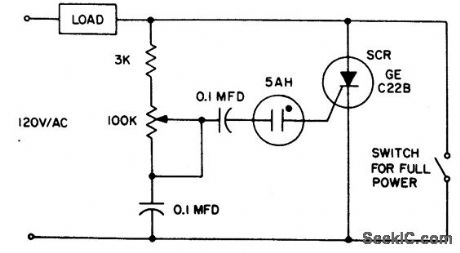
The 5AH will trigger when the voltage across the two 0.1 μF capacitors reaches the breakdown voltage of the lamp. Control can be obtained full off to 95% of the half wave RMS output voltage. Full power can be obtained with the addition of the switch across the SCR. (View)
View full Circuit Diagram | Comments | Reading(754)
LOW_LOSS_BRIGHTNESS_CONTROL
Published:2009/6/25 2:04:00 Author:May
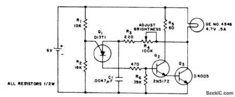
This circuit changes the average value of the dc supply voltage because of the high switching frequency. The tungsten lamp will have an almost continuous adjustable light output between 0 and 100%. If a light emitting diode is used as the emitting device, the iradiance will be in phase with the applied current pulses and will decrease to zero when the supply current is zero. (View)
View full Circuit Diagram | Comments | Reading(744)
ZERO_POINT_SWITCH
Published:2009/6/25 2:01:00 Author:May
View full Circuit Diagram | Comments | Reading(1386)
COMPLEMENTARY_AC_POWER_SWITCHING
Published:2009/6/25 2:11:00 Author:Jessie
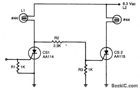
An input signal of less than 1 mA and 1 V is required to switch on CS1. As long as this input signal is maintained, CS1 will conduct during each positive half cycle of anode voltage, thereby energizing load L1 with half-wave rectified dc. L2 remains de-energized, since the anode of CS1 will not go more positive than 1.5 volts, and voltage divider R2 - R3 cannot provide enough voltage to trigger CS2. Upon removal of the input signal, CS1 will drop out.L1 will be de-energized, except for a small amount of ac current through R2 and R3. CS2will be triggered on at the beginning of each positive half-cycle, when CS1 anode voltage reaches 2 to 3 volts. CS2 will conduct for nearly the entire positive half-cycle energizing L2. It should be noted that the 6.3 volt lamps used will operate at 1/3 the rated brilliance because of the controlled switch half-wave rectifying action and will extend the operating lamp life by several orders of magnitude. Should full brilliance be desired, the anode supply voltage level should be raised to 9 volts ac. (View)
View full Circuit Diagram | Comments | Reading(1339)
LOW_COST_LAMP_DIMMER
Published:2009/6/25 1:59:00 Author:Jessie
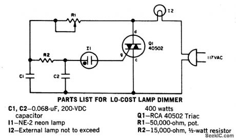
Without a heatsink, Triac Q1 handles up to a 400-watt lamp. The neon lamp does not trip the gate until it conducts so the lamp turns on a medium brilliance. The lamp can then be backed off to a soft glow. (View)
View full Circuit Diagram | Comments | Reading(0)
800_W_SOFT_START_LIGHT_DIMMER
Published:2009/6/25 1:58:00 Author:Jessie

View full Circuit Diagram | Comments | Reading(0)
860_WATT_LIMITED_RANGE_LOW_COST_PRECISION_LIGHT_CONTROL
Published:2009/6/25 1:56:00 Author:Jessie
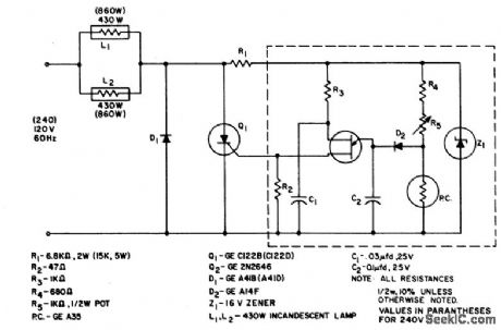
The system is designed to regulate an 860 a watt lamp load from half to full power. This is achie ved by the controlled-half-plus-fixed-half-wave phase control method. Half power applied to an incandescent lamp results in 30% of the full light output. Consequently the circuit is designed to control the light output of the lamp from 30% to 100% of maximum. (View)
View full Circuit Diagram | Comments | Reading(539)
FULL_WAVE_SCR_CONTROL
Published:2009/6/25 1:51:00 Author:May
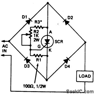
This circuit enables a single SCR to provide fullwave control of resistive loads. Resistor R3 should be chosen so that when potentiometer R2 is at its minimum setting, the current in the load is at the required minimum level. Diodes should have same current and voltage rating as the SCR. (View)
View full Circuit Diagram | Comments | Reading(975)
HYSTERESIS_FREE_PHASE_CONTROL_CIRCUIT
Published:2009/6/25 1:48:00 Author:May
This circuit is intended for lamp dimming and similar applications. It requires only one RC phase lag network. To avoid the hysteresis (or snap-on ) effect, the capacitor is reset to approximately 0 volts at the end of every positive half cycle using the gate lead. (View)
View full Circuit Diagram | Comments | Reading(871)
FLOODLAMP_POWER_CONTROL
Published:2009/6/25 1:44:00 Author:May
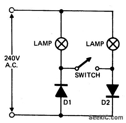
When setting up photographic floodlamps, it is sometimes desirable to operate the lamps at lower power levels until actually ready to take the photograph. The circuit allows the lamps to operate on half cycle power when the switch is open, and full power, when the switch is closed. The diodes D1 and D2 should have a 400 volt PIV rating at 5 amps. (View)
View full Circuit Diagram | Comments | Reading(648)
COMPLE_ME_NTARY_LIGHTING_CONTROL
Published:2009/6/25 1:43:00 Author:May
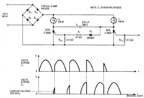
This lighting-control unit will fade out one lamp while simultaneously increasing the light output of another. The two loads track each other accurately without adjustments. The gate of SCR1, a silicon-controlled rectifier, is driven from a standard phase-control circuit, based, for example, on a unijunction transistor or a diac. It controls the brightness of lamp L1 directly. Whenever SCR1 is not on, a small current flows through L1, D1, and R1, permitting SCR2 to fire. When SCR1 turns on, current flow ceases through D1 and R1; the energy stored in C1 produces a negative spike that turns SCR2 off. (View)
View full Circuit Diagram | Comments | Reading(775)
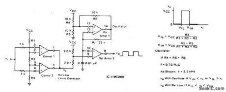
HIGH_LOW_LIMIT_ALARM
Published:2009/6/25 1:38:00 Author:May
View full Circuit Diagram | Comments | Reading(0)
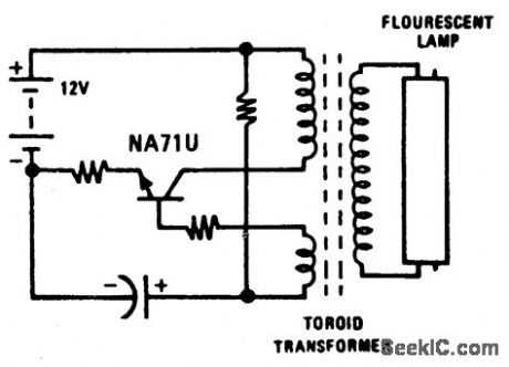
REMOTE_CONTROL_FOR_LAMP_OR_APPLIANCE
Published:2009/6/25 1:38:00 Author:May
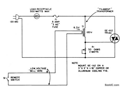
The circuit uses the primary current of a small6.3 volt filament transformer to actuate a triac and energize the load. When switch S1, in the six-volt secondary, of the transformer is open, a small magnetizing current flows through the primary winding. This magnetizing current may be large enough to trigger the triac. Therefore, a shunting resistor, R1, is required to prevent such triggering. R1, is adjusted for the highest resistance that will not cause the triac to trigger with S1 open. When single-pole remote switch, S1, closes, the secondary of the transformer is shorted and a high current flows through the 120-volt primary.This triggers the triac and energizes the load.When the triac conducts, current through the primary stops and thus prevents burning out the transformer. (View)
View full Circuit Diagram | Comments | Reading(0)
UNDERVOLTAGE_OVERVOLTAGE_INDICATOR
Published:2009/6/25 1:36:00 Author:Jessie
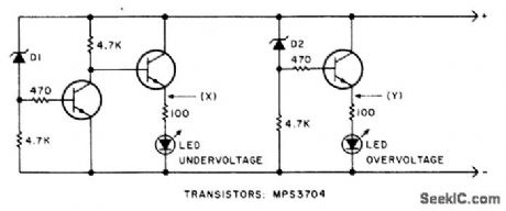
This circuit will make the LED glow if the monitored voltage goes below or above the value determined by zener diodesD1 and D2. (View)
View full Circuit Diagram | Comments | Reading(0)
LIGHT_DIMMERS
Published:2009/6/25 1:35:00 Author:Jessie
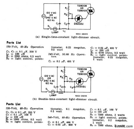
The two lamp-dimmer circuits differ in that (a) employs a s ingle-time-constant trigger network and (b) uses a double-time-constant trigger circuit that reduces hysteresis effects and thereby extends the effective range of the light-control potentiometer. (Hysteresisrefers to a difference in the control potentiometer setting at which the lamp turns on and the setting at which the light is extinguished.) The additional capacitor C2 in (b) reduces hysteresis by charging to a higher voltage than capacitor C3. During gate triggering, C3 discharges to form the gate current pulse.Capacitor C2, however, has a longer discharge time constant and this capacitor restores some of the charge removed from C3 by the gate current pulse. (View)
View full Circuit Diagram | Comments | Reading(0)
LIGHT_BEAM_OPERATED_ON_OFF_RELAY
Published:2009/6/24 23:50:00 Author:May
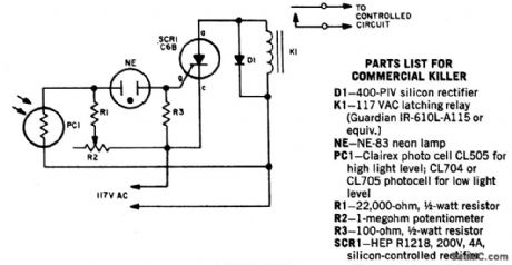
When a beam of light strikes the photocell, the voltage across neon lamp NE-1 rises sharply. NE-1 turns on and fires the SCR. K1 is an impulse relay whose contacts stay in position even after coil current is removed. The first impulse opens K1's contacts, the second impulse closes them, etc. (View)
View full Circuit Diagram | Comments | Reading(1043)
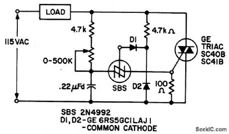
LIGHT_ISOLATED_SOLID_STATE_POWER_RELAY_CIRCUITS
Published:2009/6/24 23:48:00 Author:May
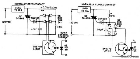
Both circuits use the G.E. SC146B, 200 V, 10 A Triac as load current contacts. These triacs are triggered by normal SBS (2N4992) trigger circuits, which are controlled by the photo-Darlington, acting through the DA806 bridge as an ac photo switch. To operate the relays at other line voltages the asterisked (*) components are scaled to supply identical current. Ratings must be changed as required.Incandescent lamps may be used in place of the light emitting diodes, if desired. (View)
View full Circuit Diagram | Comments | Reading(1726)
PHOTOCELL_MEMORY_SWITCH_FOR_AC_POWER_CONTROL
Published:2009/6/24 23:42:00 Author:May
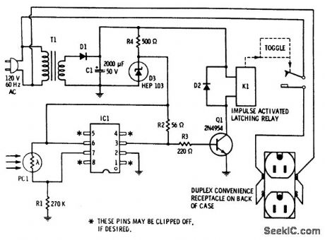
Provides remote control for ac-powered devices by using the beam of a flashlight as a magic wand. The important aspect of this gadget is that it remembers. Activate it once to apply power to a device and it stays on. Activate it a second time and power goes off and stays off. It consists of a combination of a high-sensitivity photocell, a highgain IC Schmitt trigger, and an impulse-actuated latching relay. (View)
View full Circuit Diagram | Comments | Reading(0)
CARRIER_CURRENT_REMOTE_CONTROL_OR_INTERCOM
Published:2009/6/24 23:34:00 Author:May
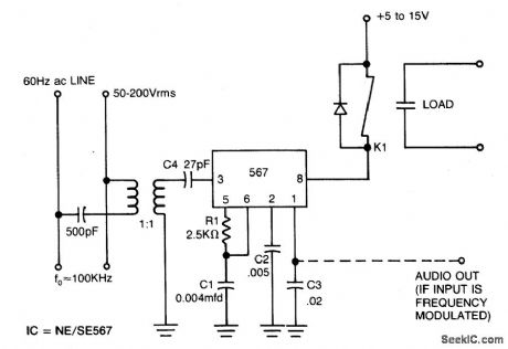
View full Circuit Diagram | Comments | Reading(674)
| Pages:165/312 At 20161162163164165166167168169170171172173174175176177178179180Under 20 |
Circuit Categories
power supply circuit
Amplifier Circuit
Basic Circuit
LED and Light Circuit
Sensor Circuit
Signal Processing
Electrical Equipment Circuit
Control Circuit
Remote Control Circuit
A/D-D/A Converter Circuit
Audio Circuit
Measuring and Test Circuit
Communication Circuit
Computer-Related Circuit
555 Circuit
Automotive Circuit
Repairing Circuit