
Control Circuit
Index 169
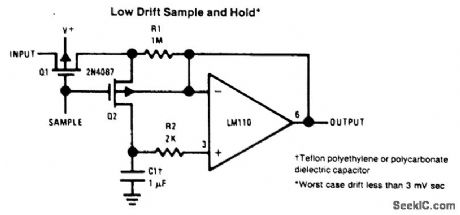
LOW_DRIFT_SAMPLE_AND_HOLD
Published:2009/6/24 20:59:00 Author:Jessie
View full Circuit Diagram | Comments | Reading(0)
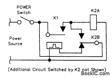
LOW_FREQUENCY_RELAY_OSCILLATOR
Published:2009/6/24 5:42:00 Author:Jessie
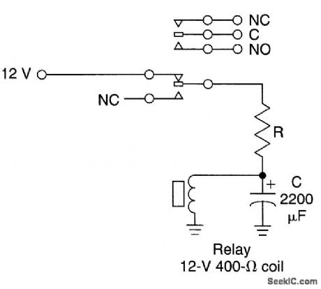
Depending on the value of C and the resistance of the relay coil, and the difference in pull-in and drop-out voltage, this circuit will oscillate at a low frequency. R limits in rush current to capacitor C to a level that the relay contacts can handle. Typically, for a 400-Ω relay, R can be 20 to 440 ohms.Flash rate is approximately 1 cycle/second, depending on the relay. (View)
View full Circuit Diagram | Comments | Reading(2905)
MOMENTARY_RELAY_CIRCUIT
Published:2009/6/24 5:33:00 Author:May
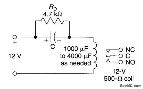
The charging current of a capacitor can be used if a momentary relay-on circuit is needed Depending fin the relay characteristics,C will vary from 1000 to 4000 μF or so for a 1-s hold time if a 500-Ω relay is used.RD discharges capacitor C to reads,the circuit for the next oPeration The valueshould be high enoughso as notto maintian the relay closure at highest expected supply voltage. (View)
View full Circuit Diagram | Comments | Reading(3050)
LATCHING_RELAY_ALARM_CIRCUIT
Published:2009/6/24 5:30:00 Author:May
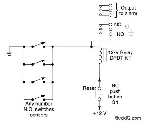
Momentarily closing any sensors will cause K1 to latch. S1 must be depressed to reset circuit. If any sensor is still closed circuit will not reset. (View)
View full Circuit Diagram | Comments | Reading(1398)
LOW_DROPOUT_THREE_TERMINAL_REGULATORS_FOR_NEW_MICROPROCESSOR_APPLICATIONS
Published:2009/6/24 5:20:00 Author:May
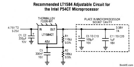
The LT1584/LT1585/LTL1587 are high-perf ormance, low-dropout regulators designed to meet the demands of the newest high speed, low voltage microprocessors. These devices are designed to regulate from 5-V supplies to output voltages between 1.25 V and 3.6 V. The LT1584 can provide up to 7 A of current, making it ideal for powerful Pentium processor or similar applications. The LT1585 can supply up to 4 A, while the LT1587 supplies up to 3 A. The excellent transient response capabil-tty allows thent to maintain good regulation even with significant load steps. Fixed 3.3 V, 3.45 V, 3.6 V and adjustable output voltages are available. (View)
View full Circuit Diagram | Comments | Reading(1367)
LOGIC_CONTROL_OF_78XX_REGULATOR
Published:2009/6/24 5:09:00 Author:May
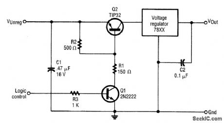
Transistors can be used to contorl any 78xx series regulator with logic signals.Both transistors are controlled by the logic level present at the base of Q1. (View)
View full Circuit Diagram | Comments | Reading(808)
TREBLE_CONTROL_CIRCUIT
Published:2009/6/24 4:40:00 Author:May
This tone control has an insertion loss of 20 dB at flat setting and is effective above 1 kHz,It little effect below about 1 kHz. (View)
View full Circuit Diagram | Comments | Reading(0)
LAMP_TIMER
Published:2009/6/24 4:35:00 Author:May

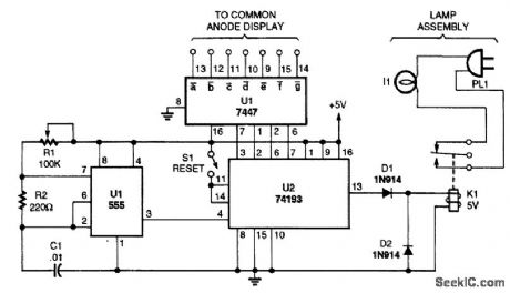
A timed switch uses a 555 oscillator/timer wired to operate in the astable mode. The timer sup-plies a positive pulse to the clock input of a 74193 4-bit binary up/down count every five minutes. Be-cause the 74193 is set to operate in the count-down mode, the output of the 555 is connected to the count-down input of the 74193.As the binary counter is reset, it starts counting at nine and counts down to zero with each clock pulse. When the counter hits zero, the output from the 74193 goes low, tuming off the relay and the light. The light can be tumed back on by pressing the reset button again. (View)
View full Circuit Diagram | Comments | Reading(7157)
ALARM_CLOCK_TIMER
Published:2009/6/24 4:34:00 Author:May

Turn your alarm clock into a specialized timer with this simple circuit. The clock used with the circuit should be the kind that turns on a little lamp when the alarm is activated. (View)
View full Circuit Diagram | Comments | Reading(0)
ACTIVE_BASS_AND_TREBLE_TONE_CONTROL
Published:2009/6/24 4:41:00 Author:Jessie
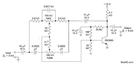
A single transistor used as a feedback amplifier is connected with ac feedback through the tone controls, which determine the frequency response of the stage. (View)
View full Circuit Diagram | Comments | Reading(1834)
COMBINED_BASS_AND_TREBLE_CONTROL
Published:2009/6/24 4:41:00 Author:Jessie
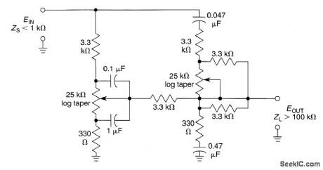
This positive tone control system uses two pots to control bass and treble. (View)
View full Circuit Diagram | Comments | Reading(726)
BASS_TONE_CONTROL_CIRCUIT
Published:2009/6/24 4:40:00 Author:Jessie
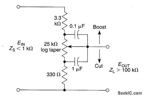
This tone control has an insertion loss of 20 dB at flat setting and is effective below 350 Hz. The control has little effect above this frequency. (View)
View full Circuit Diagram | Comments | Reading(1014)
IMPROVED_THERMOSTATIC_RELAY_CIRCUIT
Published:2009/6/24 4:24:00 Author:May
View full Circuit Diagram | Comments | Reading(693)
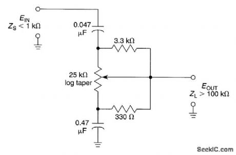
TREBLE_CONTROL_CIRCUIT
Published:2009/6/24 4:40:00 Author:Jessie
This tone control has an insertion loss of 20 dB at flat setting and is effective above 1 kHz,It little effect below about 1 kHz. (View)
View full Circuit Diagram | Comments | Reading(1206)
SPEED_SWITCH
Published:2009/6/24 4:24:00 Author:May
View full Circuit Diagram | Comments | Reading(1221)
LONG_PERIOD_TIMER
Published:2009/6/24 4:38:00 Author:Jessie
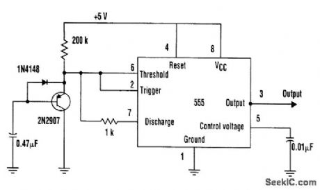
Adding a transistor to the 555 timer can create long timer periods, which is a key factor when the timer is operating at low speed. The transistor basically acts as a current divider or capacitance multiplier. The problem with low speed, however, is that the timing resistors and capacitors must be large and the charging current must be small, particularly when the desired timirtg period is in the range of seconds.
Typically, electrolytic capacitors are used in these situations, but their leakage current tends to aggravate or even prohibit operation at very low charging currents.This problem can be solved by adding a transistor. In effect, the transistor is used as a current divider or a capacitance multiplier. The normal charging current (emitter current) is divided by the transistor's current gain so that the capacitor charging current (base current) is reduced consider-ably. For example, 10μA of emitter current will require approximately 0.1 μA of base current, based on a current gain of 100.
In this circuit, the capacitor will be charged with such a low charging current that timing periods will typically be 100 times longer than usual. This means that substantial time periods can be achieved with film or ceramic capacitors that have much better leakage characteristics and are physically smaller.
The circuit's output pgriod was approximately 6 seconds, compared to 80 ms without the transistor. The transistor multiplied the normal time period by a factor of approximately 75. (View)
View full Circuit Diagram | Comments | Reading(2652)
ALARM_CLOCK_TIMER
Published:2009/6/24 4:34:00 Author:Jessie
Turn your alarm clock into a specialized timer with this simple circuit. The clock used with the circuit should be the kind that turns on a little lamp when the alarm is activated. (View)
View full Circuit Diagram | Comments | Reading(1822)
WINDSHIELD_WIPER_CONTROL
Published:2009/6/24 4:22:00 Author:May
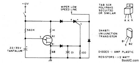
Here's a good way to set windshield wipers on an interval circuit. Only two connections to the car's wiper control, plus ground, are required. Variable control can be accomplished by substituting a 500 K pot in series with a100 K fixed resistor in place of the 560 K. (View)
View full Circuit Diagram | Comments | Reading(1211)
LM3911_TEMPERATURE_CONTROLLER
Published:2009/6/24 4:21:00 Author:May
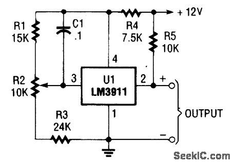
The LM3911 requires only a few resistors and a capacitor to tum into a full-function tem-perature controller. The LM3911 requires very few external components to implement a full-function temperature controller. The figure illus-trates the sirnplicity of the freeze fighter circuit.The resistor network consisting of R1, R2, and R3 is used to provide the set point voltage for the feedback input of the LM3911.Resistor R4 limits the current through the in-ternal voltage reference of the LM3911 and can be selected from a wide range of values. 7.5 kQ is specified in most of the application notes.Resistor R5 pulls the output of the IC high when the temperature is below the set point. The internal resistor is in series with a diode that al-lows a switching voltage up to 35 V to be used with the device. (View)
View full Circuit Diagram | Comments | Reading(729)
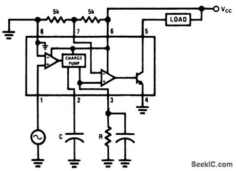
TEMPERATURE_TO_FREQUENCY_CONVERTER_KELVIN
Published:2009/6/24 4:17:00 Author:May
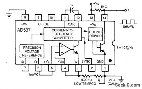
This simple connection results in a direct conversion of temperature to frequency. The 1-mV/°K temperature output serves as the input to the buffer amplifier, and the oscillator drive current is scaled to be 298μA at 298°K (+25℃). Use of a 1000-pF capacitor results in a corresponding fre-quency of 2.98 kHz. A single-point trim for calibration is normally sufficient to give errors less than ±2℃ from -55℃ to +125℃. An NPO capacitor is preferred to minimize nonlinearity that results from capacitance drift. (View)
View full Circuit Diagram | Comments | Reading(1675)
| Pages:169/312 At 20161162163164165166167168169170171172173174175176177178179180Under 20 |
Circuit Categories
power supply circuit
Amplifier Circuit
Basic Circuit
LED and Light Circuit
Sensor Circuit
Signal Processing
Electrical Equipment Circuit
Control Circuit
Remote Control Circuit
A/D-D/A Converter Circuit
Audio Circuit
Measuring and Test Circuit
Communication Circuit
Computer-Related Circuit
555 Circuit
Automotive Circuit
Repairing Circuit