
Control Circuit
Index 162
TEMPERATURE_CONTROLLER_1
Published:2009/6/25 23:15:00 Author:May
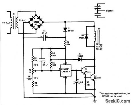
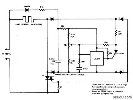
The sensor is a standard TO-5 or TO-46 package. For surface or air temperature sens-ing. Small clip-on heat sinks can be used. A simple probe can be made using heat-shrink tubing and RTV silicon rubber. Three-leads-plus-shield cable is a good choice for wire with the shield connected to pin 4. The controller can be used for baths, ovens, oven-temperature protection, or even home thermostats. Long-term stability and repeatability is better than 0.5 ℃. (View)
View full Circuit Diagram | Comments | Reading(0)
SINGLE_SETPOINT_TEMPERATRE_CONTROLLER
Published:2009/6/25 23:13:00 Author:May
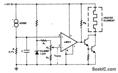
Ths AD590 produces a temperature-dependent voltage across R (C is for filtering noise). Setting R2 produces a scale-zero voltage. For the Celsius scale, make R=1K and Vzero=0.273 volts. For Fahrenheit, R=1.8K and Vzero=0.460 volts. (View)
View full Circuit Diagram | Comments | Reading(686)
PORTABLE_CALIBRATOR
Published:2009/6/25 23:19:00 Author:Jessie
View full Circuit Diagram | Comments | Reading(620)
TEMPERATURE_CONTROLLER_2
Published:2009/6/25 23:19:00 Author:Jessie
View full Circuit Diagram | Comments | Reading(650)
TEMPERATURE_CONTROLLER
Published:2009/6/25 23:09:00 Author:May
View full Circuit Diagram | Comments | Reading(0)
1MOTOR_SPEED_CONTROL
Published:2009/6/25 23:06:00 Author:May
Switching action of the 2N4990 allows smaller capacitors to be used while achieving reliable thyristor triggering. (View)
View full Circuit Diagram | Comments | Reading(918)
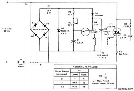
HIGH_TORQUE_MOTOR_SPEED_CONTROL
Published:2009/6/25 23:04:00 Author:Jessie
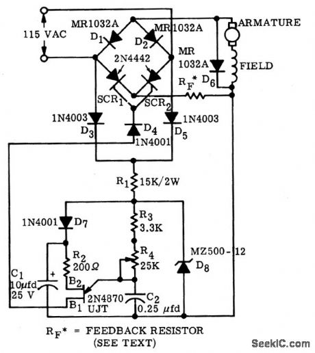


A bridge circuit consisting of two SCRs and two silicon rectifiers furnishes full-wave opower to the motor.Diodes,D3 and D5,supply dc to the trigger circuit through dropping reslstors,R1.Phase delay of SCR firing is obtained by charging C2 through resistors R3 and R4 from the voltage level established by the zener dione,D8.When C2 charges to the firing voltage of the unijunction transistor,the UJT fires,triggering the SCR that has a positive on its anode,When C2 discharges sufficiently,the unijunction transistor drops out of conduction.The value of RF is dependent upon the size of the motor and on the amount of feedback desired.A typical value for RF can be calculated from: RF=-2/IM where SIM is the max rated load current(rms)。 (View)
View full Circuit Diagram | Comments | Reading(1729)
TEMPERATURE_SENSITIVE_HEATER_CONTROL
Published:2009/6/25 22:58:00 Author:Jessie

View full Circuit Diagram | Comments | Reading(745)
THREE_WIRE_ELECTRONIC_THERMOSTAT
Published:2009/6/25 22:56:00 Author:Jessie
View full Circuit Diagram | Comments | Reading(794)
TWO_WIRE_REMOTE_AC_ELECTRONIC_THERMOSTAT(GAS_OR_OIL_FURNACE_CONTROL)
Published:2009/6/25 22:55:00 Author:Jessie
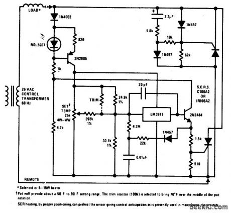
View full Circuit Diagram | Comments | Reading(764)
HEATER_CONTROL
Published:2009/6/25 22:54:00 Author:Jessie
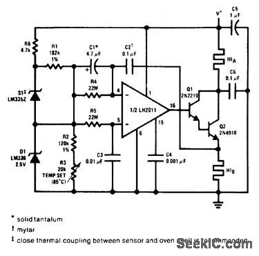
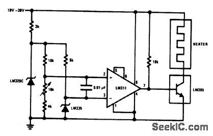
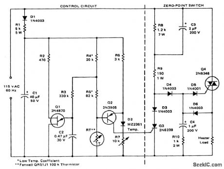
This proportional control crystal oven heater uses lead/lag compensation for fast set-ting. The time constant is changed with R4 and compensating resistor R5. If Q2 is inside the oven, a regulated supply is recommended for 0.1 ℃. control. (View)
View full Circuit Diagram | Comments | Reading(1348)
TWO_ROTATOR_CONTROL
Published:2009/6/25 22:52:00 Author:Jessie
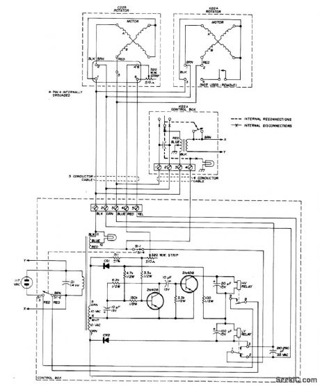
Low-cost Alliance C-225 TV antenna rotator and Alliance K22A ro-tator with control box are used with single tran-sistorized-bridge control circuit. Rotators op-erate in tandem on same shaft to provide double torque for handling medium-size 20-meter amateur radio antennas. One arm of bridge is 520-ohm wirewound pot in which wiper position is proportional to heading. Artiole covers wiring and bench-testing of rotators.-F.E.Gehrke,Antenna Rotator for Medium-sized Beams,Ham Radio,May 1976、p48-51. (View)
View full Circuit Diagram | Comments | Reading(4118)
MOTOR_SPEED_CONTROL_WITH_FEEDBACK
Published:2009/6/25 22:45:00 Author:May
View full Circuit Diagram | Comments | Reading(728)
PLUG_IN_SPEED_CONTROL_FOR_TOOLS_OR_APPLIANCES
Published:2009/6/25 22:43:00 Author:May
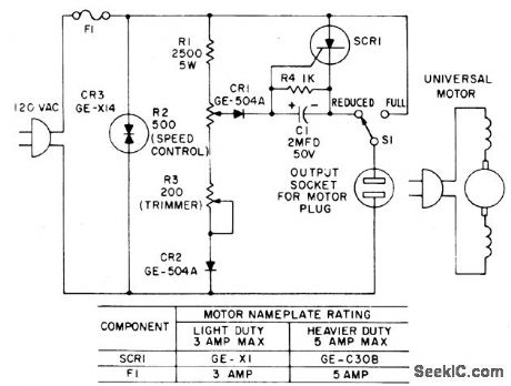
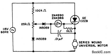
Most standard household appliances and portable hand tools can be adapted to variablespeed operation by use of this simple half-wave SCR phase control. It can be used as the speed control unit for the following typical loads providee they use series universal (brush type) motors.
DrillsFansSewing Machines LathesSaber saws VibratorsPortable band saws Movie projectors Food mixers SandersFood blendersDuring the positive half cycle of the supply voltage, the arm on potentiometer R2 taps off a traction of the sine wave supply voltage and compares it with the counter emf of the motor through the gate of the SCR. When the pot voltage rises above the armature voltage, current flows through CR1 into the gate of the SCR, triggering it, and thus applying the remainder of that half cycle supply voltage to the motor. The speed at which the motor operates can be selected by R2. Stable operation is possible over approximately a 3-to-1 speed range.
(View)
View full Circuit Diagram | Comments | Reading(1229)
DIRECTION_AND_SPEED_CONTROL_FOR_SERIES_WOUND_MOTORS
Published:2009/6/25 22:49:00 Author:Jessie

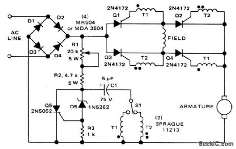
The circuit shown here can be used to control the speed and direction of rotation of a series-wound dc motor. Silicon controlled rectifiers Q1-Q4, which are connected in a bridge arrangement, are triggered in diagonal pairs. Which pair is turned on is controlled by switch St since it connects eithercoupling transformer T1 or coupling transformer T2 to a pulsing circuit. The current in the field can be reversed by selecting either SCRs Q2 and Q3 for conduction, or SCRs Q1 and Q4 for conduction. Since the armature current is always in the same direction, the field current reverses in relation to the armature current, thus reversing the direction of rotation of the motor. A pulse circuit is used to drive the SCRs through either transformer T1 or T2. The pulse required to fire the SCR is obtained from the energy stored in capacitor C1. (View)
View full Circuit Diagram | Comments | Reading(1)
BOILER_CONTROL
Published:2009/6/25 22:43:00 Author:May
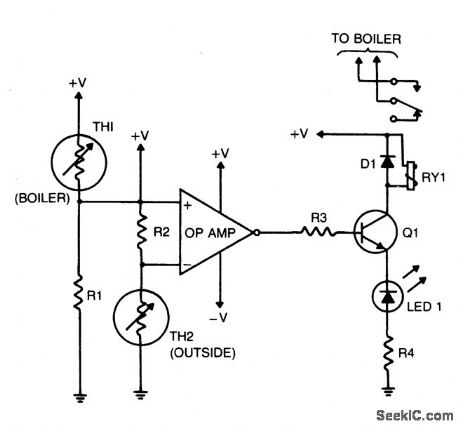
The purpose of this circuit is to control the water temperature in a hot-water heating sys-tem. What it does is to lower the boiler tem-perature as the outside air temperature in-creases. The op amp is used as a comparator. Therrnistor TH2 and R2 form a voltage divider that supplies a reference voltage to the op-amp's inverting input. Thermistor TH2 is placed outdoors, and the values of TH2 and R2 should be chosen so that when the outside temperature is 25 °F, the resistance of the thermistor and resistor are equal. Resistor R1 and thermistor TH1 make up a voltage divider that supplies a voltage to the op amp's nonin-verting input. Thermistor TH1 is placed inside the boiler and the values of TH1 and RI should be chosen so that when the boiler's tempera-ture is 160 °F, their resistances are equal. The output of the op amp controls Q1, which is configured as a transistor switch. When the logic output of the op amp is high, Q1 is turned on, energizing relay RY1. The relay's contacts should be wired so that the boiler's heat supply is turned off (relay energized). (View)
View full Circuit Diagram | Comments | Reading(2345)
MOTOR_SPEED_CONTROL
Published:2009/6/25 22:39:00 Author:May
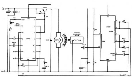
This circuit is a regulating series dc motor speed control using the LM3524 for the control and drive for the motor and the LM2907 as a speed sensor for the feedback network. (View)
View full Circuit Diagram | Comments | Reading(4242)
RAIN_ALARM/DOOR_BELL
Published:2009/6/25 22:37:00 Author:May
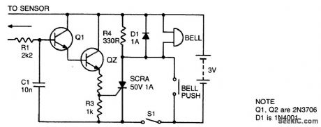
With S1 open the circuit functions as a doorbell. With S1 closed, rain falling on the sensor will turn on Q1, triggering Q2 and the thyristor and activating the bell, R4 provides the holding for the thyristor while D1 prevents any damage to the thyristor from back EMF in the bell coil. The sensor can be made from 3 square inches of copper clad board with a razor cut down the center. C1 prevents any mains pickup in the sensor leads. (View)
View full Circuit Diagram | Comments | Reading(725)
RAIN_ALARM
Published:2009/6/25 22:31:00 Author:Jessie
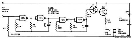
The circuit uses four NAND gates of a 4011 package. In eachoscillator, while one gate is configured as a straightforward inverter, the other has one input that can act as a control input. Oscillator action is inhibited if this input is held low. The first oscillator (IC1a and IC1b) has this input tied low via a high value resistor (R1) that acts as a sensitivity control. Thus this oscillator will be disabled until the control input is taken high. Any moisture bridging the sensor track will so enable the output which is a square wave at about 10 Hz. This in turn will gate on and off the 500 Hz oscillator formed by IC1c and IC1d. This latter oscillator drives the loudspeaker via R6, the Darlington pair formed by Q1 and Q2, and resistor R7. (View)
View full Circuit Diagram | Comments | Reading(0)
TELEPHONE_RELAY
Published:2009/6/25 22:17:00 Author:May
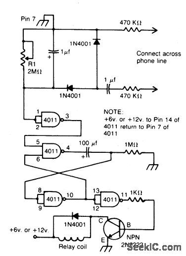
Connected across the bell circuit of phone, this circuit closes a relay when the phone is ringing. Use the delay contacts to actuate any bell, siren, buzzer or lamp. (View)
View full Circuit Diagram | Comments | Reading(1154)
| Pages:162/312 At 20161162163164165166167168169170171172173174175176177178179180Under 20 |
Circuit Categories
power supply circuit
Amplifier Circuit
Basic Circuit
LED and Light Circuit
Sensor Circuit
Signal Processing
Electrical Equipment Circuit
Control Circuit
Remote Control Circuit
A/D-D/A Converter Circuit
Audio Circuit
Measuring and Test Circuit
Communication Circuit
Computer-Related Circuit
555 Circuit
Automotive Circuit
Repairing Circuit