
Control Circuit
Index 173
200_V_REGULATOR
Published:2009/6/24 1:55:00 Author:May
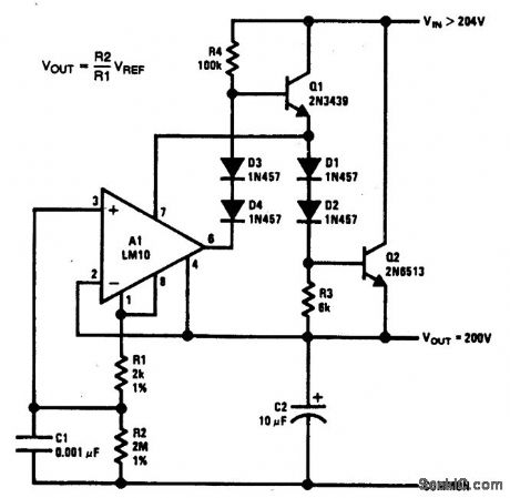
With high-voltage regulators, powering on the IC through the drive resistor for the pass transistors can become quite inefficient. This is avoided with the circuit shown. The supply current for the IC is derived from Q1. This allows R4 to be increased by an order of magnitude without affecting the dropout voltage.Selection of the output transistors will depend on voltage requirements. For output voltages above 200 V, it might be more economical to cascade lower-voltage transistors. (View)
View full Circuit Diagram | Comments | Reading(778)
Multivibrator Circuit Composed of Photocoupler
Published:2011/7/19 21:53:00 Author:Sue | Keyword: Multivibrator, Photocoupler
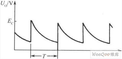
As seen in the figure 1, photocoupler composes the simplest multivibrator. After the power is on, as capacitor C's voltage can't change abruptly and resistor R's resistancevalue is larger than RL, so the power voltage Ec is mainly put on R. F's level is very low and LED is disconnected. As the capacitor's charging voltage is becoming larger and larger, F's level is becoming higher and higher. When it reaches a certain value, the LED will be connected and will be illuminated. The photistor will be connected. The output voltage will jump and become close to the power voltage. (View)
View full Circuit Diagram | Comments | Reading(587)
HIGH_VOLTAGE_POWER_SUPPLY_CONTROL_CIRCUIT
Published:2009/6/24 1:41:00 Author:May
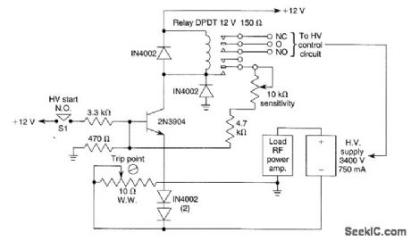

To start the HV supply, S1 is pressed,latching the relay.The 10-kΩ pot is set so that the relayjust latches. When HV current becomes excessive(arc-over,etc.) ,an excessive voltage is developedacross the 10-Ω WW pot,cutting off the 2N3904,causing the relay to unlatch This circuit was used in a 1000-W linear RF power amplifier. (View)
View full Circuit Diagram | Comments | Reading(1184)
Motor Control Circuit of LM339
Published:2011/7/17 10:22:00 Author:Michel | Keyword: Motor, Control, Circuit
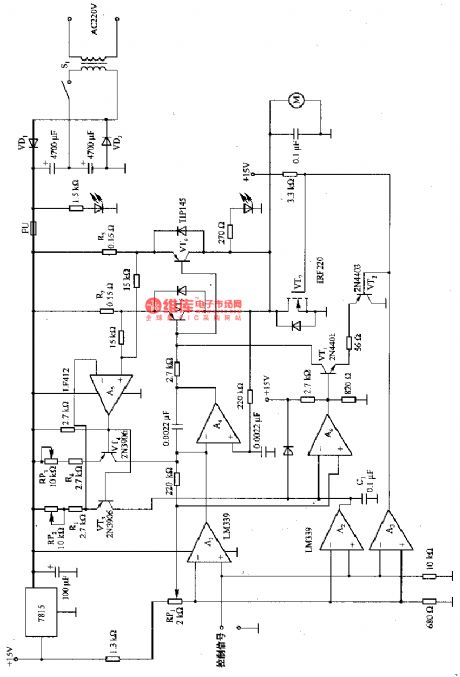
The above picture is the motor control circuit composed of LM339 etc.When the input control signal is high PWL,comparator A and A3 make power amplifier conduct composed of A4,VT5 and VT6 and it drives motor M.At the same time,comparator also outputs and removes the armature current integral capacitance C1 reset.The armature current monitors the current enters C1 through A5 and VT3.When RP2 adjustable proportional is constant, the current that enters C1 ,R2 Cl and R3 resistance test armature currentare in proportion.As long as comparator compares the voltage on C1 with RP1 setting voltage,A6 will output high PWL as long as voltage on C1 is lower than RP1 setting voltage. (View)
View full Circuit Diagram | Comments | Reading(4365)
Load Experiment Control Circuit
Published:2011/7/17 10:21:00 Author:Michel | Keyword: Load Experiment, Control Circuit
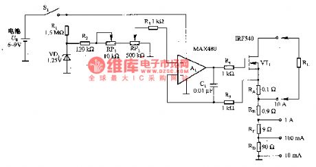
The above picture is load expriement control circuit.The largest external load of this circuit can reach up to 10 A and it's widely used in the exprimental power supply,power amplifier, bearing capacity experiments of the LED and relay and solenoid. Different from the general resistance loading,it keeps the experiment load constant through regulating 1.2-50V voltage range's load current.Circuit adopts power MOS-an FET (VTl) and measuring resistance (RA a RD) to consump load power and the battery is used to isolate so as to solve the ground work. RP2 uses ten laps, which improves the precision and potentiometer resolution.
(View)
View full Circuit Diagram | Comments | Reading(606)
HIGH_VOLTAGE_REGULATOR
Published:2009/6/24 1:35:00 Author:May
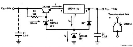
This circuit produces 48 V from an 80-V input. (View)
View full Circuit Diagram | Comments | Reading(3)
ASTABLE_MULTIVIBRATOR_OR_FREE_RUNNING_SQUARE_WAVE_OSCILLATOR
Published:2009/6/23 22:28:00 Author:Jessie
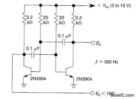
This free-running square-wave oscillator uses two npn transistors. Output frequency is approximately 300 Hz with the values shown. (View)
View full Circuit Diagram | Comments | Reading(965)
SPEED_CONTROL_SWITCH
Published:2009/6/23 22:15:00 Author:Jessie
The speed-control switch offers reasonably good control and stability to both ends of its operating range. This circuit uses two SCR devices in a full-wave configuration to control the dc power to a motor. A center-tapped transformer is used to supply the SCRs. (View)
View full Circuit Diagram | Comments | Reading(1532)
PULSE_WIDTH_MODULATED_MOTOR_SPEED_CONTROL
Published:2009/6/23 22:09:00 Author:Jessie
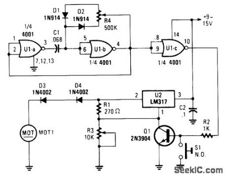
Connected in this manner, an LM317 1-A adjustable-voltage regulator can be used to control the speed of a miniature dc motor or vary the brilliance of a small lamp. The circuit does so by controlling the pulse width, and therefore the current, to the load device.
To set the desired maximum output voltage, momentarily close 51 and adjust R3. Connect either a lamp or small dc motor (as is shown in the schematic to the circuit's output) and adjust R4 for the desired results. Atv device that is driven by this circuit should have a current requirement of 1 A or less. And you should be sure to use good-sized heatsink for the LM317 regulator IC. (View)
View full Circuit Diagram | Comments | Reading(1152)
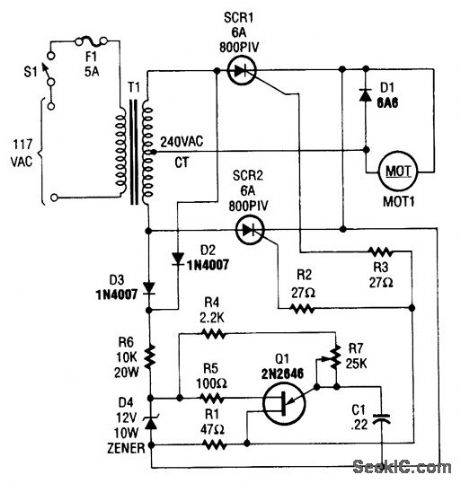
SPEED_CONTROL_SWITCH_CIRCUIT
Published:2009/6/23 22:03:00 Author:Jessie

A center-tapped 240-V transformer is used with two SCR devices to provide rectified ac (pulsating dc) to MOT1. Q1 is a UJT ramp generator used to generate trigger pulses for SCR1 and SCR2. (View)
View full Circuit Diagram | Comments | Reading(740)
BLENDER_CONTROL_CIRCUIT
Published:2009/6/23 21:52:00 Author:Jessie

A 10-speed touch-control blender circuit that uses the low-cost LS314 chip by LSI Systems. The 11th touch pad is for power off. (View)
View full Circuit Diagram | Comments | Reading(1922)
Motor vehicle steering light controller 1
Published:2011/7/29 3:06:00 Author:Ecco | Keyword: Motor vehicle, steering light controller
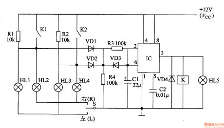
(View)
View full Circuit Diagram | Comments | Reading(546)
TWO_TERMINAL_100_mA_CURRENT_REGULATOR
Published:2009/6/23 4:14:00 Author:May
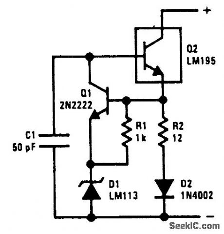
The circuit has a low temperature coefficient and operates down to 3 V. The reverse base current of the LM195 biases the circuit.
A 2N2222 is used to control the voltage across current-sensing resistor, R2 and diode D1, and therefore the current through it. The voltage across the sense network is the VBE of the 2N2222 plus 1.2 V from the LM113. In the sense network, R2 sets the current and D1 compensates for the VBE of the transistor. Resistor R1 sets the current through the LM113 to 0.6 mA. (View)
View full Circuit Diagram | Comments | Reading(824)
Vehicle flashing lights controller 5
Published:2011/7/29 2:55:00 Author:Ecco | Keyword: Vehicle, flashing lights, controller
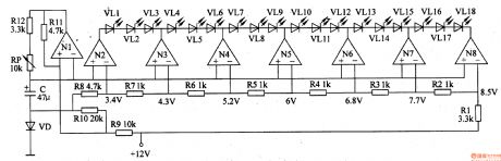
The motor vehicle flashing lights controller described in the example is composed of LED light-emitting diodes and control circuit.It can be installedin the rear window of the motorcycle or car, when driving at night, the light-emitting diode is lit like the water cycle; It can grasp people's attention.
Working principle
The motor controller circuit is composed of the LED drive circuit and oscillator, it is shownas Figure 7-29.
When the voltage of the two ends of C is lower than 3.4V, which is the reference voltage of N2, the output of N2-N8 is in low level, VLl-VLl8 are off.
When the voltage of the two ends of C ishigher than 43V, the output of N2 is in low level, and the output of N3 is in high level,VLl-VL3 are off, VL7-VL9 are on.
When the voltage of the two ends of C ishigher than 5.2V, the output of N3 is in low level, and the output of N4 is in high level,VL4-VL6 are off, VL7-VL9 are on.
When the voltage of the two ends of C ishigher than 6V, the output of N4 is in low level, and the output of N5 is in high level,VL7-VL9 are off, VL0-VL2 are on.
When the voltage of the two ends of C ishigher than 6.8V, the output of N5 is in low level, and the output of N6 is in high level,VL0-VL2 are off, VL3-VL5 are on.
When the voltage of the two ends of C ishigher than 7.7V, the output of N6 is in low level, and the output of N7 is in high level,VL3-VL5 are off, VL6-VL8 are on. (View)
View full Circuit Diagram | Comments | Reading(675)
The gas overranging alarm miner lamp 1
Published:2011/7/29 2:57:00 Author:Ecco | Keyword: gas overranging , alarm , miner lamp

The gas overranging alarm miner lamp described in the example is suitable for the environment with explosion gas in coal mine, the miners carry the device for lighting and detecting methane gas. When the methane gas is overlimit, the alarm signal will flash in time to remind miners to evacuate in time.
The working principle:The gas overranging alarm miner lamp circuit is composed of detection amplifier circuit and alarm circuit. It's shown as the figure 8-29.
The detection amplifier circuit is composed of sensor, resistors Rl-Rl5, potentiometer RP, transistors Vl-V7 and voltage regulator diode VS. The alarm circuit consists of resistors R16-Rl8, capacitors Cl-C4, transistors V8 and V9, Diodes VDl and VD2, the relay K and miner's lamp EL.Turning on the power switch S (Sl, S2), EL is lit, the entire circuit gets power supply. The end of the sensor detects methane gas, the internal resistance of pure white carrier elements B and black catalytic elements A in sensor keep stable, V6 and V7 is off, the oscillator composed of V8, V9, and Cl-C4, R16-R18, K , VDl stops vibrating, K is in releasing state, EL in normal lighting condition.
(View)
View full Circuit Diagram | Comments | Reading(711)
The gas overranging alarm miner lamp 2
Published:2011/7/29 2:58:00 Author:Ecco | Keyword: gas overranging, alarm, miners lamp
The gas overranging alarm miner lamp described in the example is based on miner's lamp or miner's helmet. It couldflash in time to remind miners paying attention on safety.
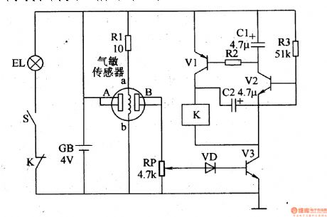
The working principle: The gas overranging alarm miner lamp circuit is composed of gasdetection circuit, controlled oscillator circuit and lighting circuit. It's shown as the figure 8-30.
The gas detection circuit is composed of gas sensor, resistors Rl and potentiometer RP. The controlled oscillator circuit is composed of the potentiometer RP, a diode VD, transistors Vl-V3, resistor R2 and R3, capacitor Cl and C2 and the relay K. The lighting circuit is composed of the battery GB, lights EL, the constant moving contact of S and K light switch. The switch S turns off, EL will be lit. The end of the gas sensor detects methane gas, the place between A and B shows the state with high resistance, VD and V3 are in the OFF state, K is not action, miner working in the lighting condition.
(View)
View full Circuit Diagram | Comments | Reading(771)
The gas overranging alarm miner lamp 3
Published:2011/7/29 2:59:00 Author:Ecco | Keyword: gas overranging , alarm, miners lamp
The gas overranging alarm miner lamp described in the example uses the batteries of miner's lamp as power supply. It is installed in the mine cap.When the gas is over the limit, the alarm signal will remind miners to evacuate in time.
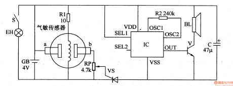
The working principle: The gas overranging alarm miner lamp circuit is composed of gas detection circuit,electronic switching circuit and sound alarm circuit. It's shown as the figure 8-31.
The gas detection circuit is composed of resistor Rl, and the gas sensor, potentiometer RP.
The electronic switching circuit is composed of thyristor VT and RP.
Thesound alarm circuit is composed of sound IC, resistor R2, transistor Vand speaker BL.
When the gas concentration is below the limit of safety standards, the conductivity between a and b of gas sensor is low, b point is in low level, VT is in the cut-off state, and IC does not work, BL does not sound.
When the gas concentration is over the limit of safety standards, the conductivity between a and b of gas sensor will increase, the voltage of b point increases, VT turns on by trigger, and IC works, the audio output signal amplified by the V will drive the alarm BL.
(View)
View full Circuit Diagram | Comments | Reading(627)
VCDO_II
Published:2009/6/23 4:41:00 Author:Jessie
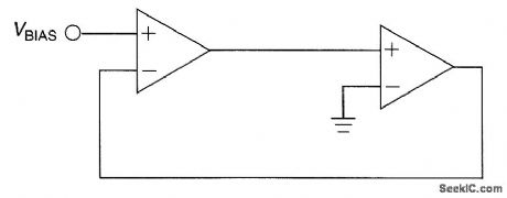
The output frequency of this simple low-cost active voltage-controlled oscillator circuit is based upon the inherent frequency dependent characteristics of our operational amplifier.
The oscillator circuit shown uses a TL082 op amp. When power is applied, the circuit generates a sinusoidal wave. The frequency of oscillation can be changed by varying the bias supply. (View)
View full Circuit Diagram | Comments | Reading(913)
The gas overranging alarm miner lamp 4
Published:2011/7/29 2:59:00 Author:Ecco | Keyword: gas overranging, alarm , miners lamp
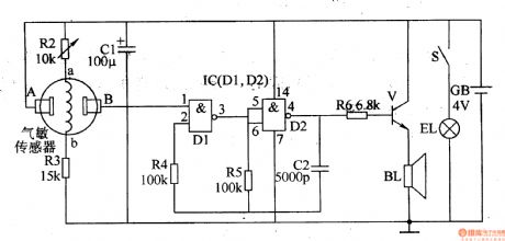
The working principle: The gas overranging alarm miner lamp circuit is composed of gas detection circuit, multivibrator, audio output circuit and lighting circuit. It's shown as the figure 8-32.
Gas detection circuitis composed ofthe gas sensor and resistors R2, R3.
Multivibrator is composed oftwo NAND gates Dl, D2 of internal NAND gate and resistors R4 and R5, capacitor C2.
Audio output circuit consists of resistors R6, audio amplification V and speaker BL.
Lighting circuit is composed of the battery GB, lights EL andK light switch.
When the indoor concentration of combustible gasis inthe allowable range (less than limit value), the resistance between the gas sensors A, B is high,the foot voltage of Ic is low, multivibrator does not work, the speaker BL has no sound. When the indoor concentration of combustible gasis over the limit, the resistance between the gas sensors A, B declines,the foot voltage of Ic is higher than conversion voltage of D1, multivibrator works,the output oscillation signal frompin 4of IC. The signal amplified by the V will promote the speaker BL.
(View)
View full Circuit Diagram | Comments | Reading(1302)
MODEL_RAILROAD_TRACK_CONTROL_SIGNAL
Published:2009/6/23 4:30:00 Author:May
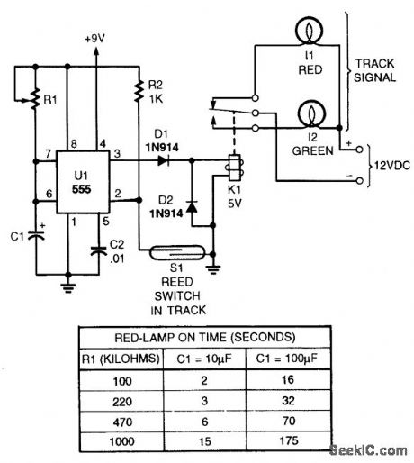
When a train passesS1 (a red switch), a small magnet glued to the underside operates Sl and causes UI to generate a pulse, activating relay K1 and changing the signal from green to red. After a time determined by RI and C1 (see table), the relay de-energizes and the signal goes back to green. (View)
View full Circuit Diagram | Comments | Reading(0)
| Pages:173/312 At 20161162163164165166167168169170171172173174175176177178179180Under 20 |
Circuit Categories
power supply circuit
Amplifier Circuit
Basic Circuit
LED and Light Circuit
Sensor Circuit
Signal Processing
Electrical Equipment Circuit
Control Circuit
Remote Control Circuit
A/D-D/A Converter Circuit
Audio Circuit
Measuring and Test Circuit
Communication Circuit
Computer-Related Circuit
555 Circuit
Automotive Circuit
Repairing Circuit