
Telephone-Related Circuit
Index 5
FCC_APPROVED_TELEPHONE_TONE_RINGER
Published:2009/6/25 22:03:00 Author:May
View full Circuit Diagram | Comments | Reading(1222)
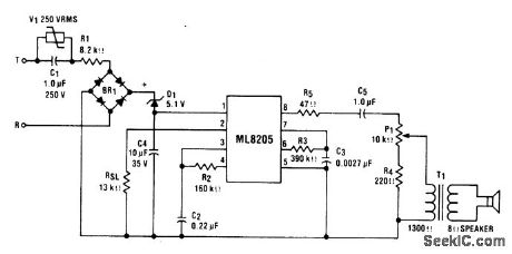
TELEPHONE_TONE_RINGER
Published:2009/6/25 22:02:00 Author:May
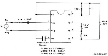
This is a complete telephone bell replacement circuit with minimum external components with on-chip diode bridge and transient protection and direct drive for piezoelectric transducers. (View)
View full Circuit Diagram | Comments | Reading(873)
THERMOCOUPLE_COLD_JUNCTION_COMPENSATION
Published:2009/6/24 4:27:00 Author:May
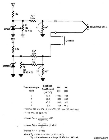
A single-supply circuit is shown. R3 and R4 divide down the 10-mV/°K output of the LM329B and its associated voltage divider provide a voltage to buck out the 0℃ output of the LM335. To calibrate, adjust R1 so that V1 = αT, where cc is the Seebeck coefficient and T is the ambient temperature in degrees Kelvin. Then, adjust R2 so that V1 - V2 is equal to the thermocouple output voltage at the known ambient temperature. (View)
View full Circuit Diagram | Comments | Reading(0)
NATIONAL_SEMICONDUCTOR
Published:2009/6/24 4:05:00 Author:May
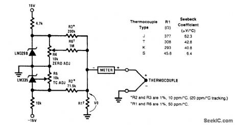
A circuit for use with grounded thermocouples is shown. To trim, short out the LM329B and ad-just R5 so that V°= αT, where cc is the Seebeck coefficient of the thermocouple and T is the absolute temperature. Remove the short and adjust R4 so that W equals the thermocouple output voltage at ambient. A good grounding system is essential here, for any ground differential will appear in series with the thermocouple output. (View)
View full Circuit Diagram | Comments | Reading(0)
PROPORTIONAL_TEMPERATURE_CONTROLLER
Published:2009/6/24 4:01:00 Author:May


Most temperature-controller circuits use upper and lower trip points to control a heater element, with the heater power full on and full off. Usually, this results in a temperature hysteresis of several degrees. This relatively large temperature hysteresis effect might cause modulation in the output of the circuit that's being controlled.
A proportional temperature controller eliminates this problem by continuously providing the power needed to maintain the oven at the desired temperature-within 1℃. From a cold start, maximum power is applied until the temperature is within 2℃ of the set point.
The circuit's mechanical construction is important. The five heater resistors (R12 through R16), the temperature-sensor IC (U1), and the circuit being controlled are mounted with thermal epoxy to a small piece of aluminum. This provides excellent heat transfer between the components. The heater resistors must be selected to raise the temperature from ambient to the set point within an acceptable warm-up time.
U1 is Analog Devices' TMP-01 temperature- controller IC. The voltage proportional to absolute temperature (VPTAT) has a temperature coefficient of exactly 5 mV/℃. The set point is determined by the R1/R2 ratio. U2 is a Linear Technology LT1014 quad precision op amp. U2C is an oscillator with a 50% duty cycle that supplies a triangle wave between 1/3 and 2/3 of the supply voltage at U2-2
U2B compares the amplified VPTAT to the triangle wave, which drives Q1 at a duty cycle of 100% or less. Because the triangle wave's peak-to-peak amplitude is 2.7 V, and VPTAT is amplified by a factor of 300, a temperature change of approximately 2 mV moves the duty cycle from 100% to 0%. (View)
View full Circuit Diagram | Comments | Reading(0)
PHONE_HELPER
Published:2009/6/24 3:44:00 Author:May
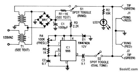
This phone-line simulator uses a 60-Hz transformer instead of a ring generator. The dial tone is provided by an NE555 astable oscillator. (View)
View full Circuit Diagram | Comments | Reading(0)
TELEPHONE_RECORDING_CIRCUIT
Published:2009/6/24 3:42:00 Author:May
This device will automatically record telephone calls. An ordinary cassette recorder can be hooked to it. (View)
View full Circuit Diagram | Comments | Reading(1171)
UNIVERSAL_TELEPHONE_HOLD_CIRCUIT
Published:2009/6/24 3:41:00 Author:May
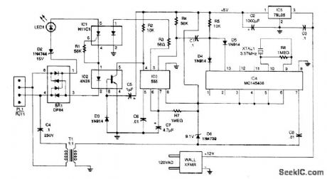
The telephone line is connected to the hold components through bridge rectifier BR1 so that the input is not polarity sensitive. If you have touch-tone telephone service, you can now put a call on hold from any phone in your house by plugging this simple device into any telephone jack. The uni-versal hold circuit works with any phone that has a key pad with a # key. To put a call on hold, press the # key and hang the phone up. A timer extends the #-key function while you hang up phones that have a keypad built into the handset. (View)
View full Circuit Diagram | Comments | Reading(1194)
TELEPHONE_SCRAMBLER
Published:2009/6/24 3:36:00 Author:May
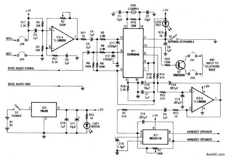
This circuit uses the usual speech inversion algorithm, implementing it with a COM9046 ASIC. This unit is designed to fit be-Lween the handset and base of a standard telephone. It is powered by a 9-V battery. (View)
View full Circuit Diagram | Comments | Reading(0)
TELEPHONE_CIRCUIT
Published:2009/6/22 22:58:00 Author:May
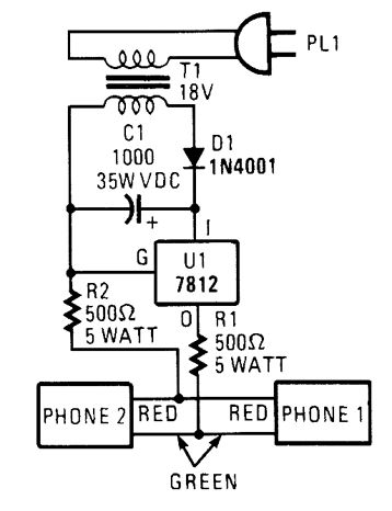
This circuit is useful for checking out old telephones by providing them with the dc voltage that they require for operation. (View)
View full Circuit Diagram | Comments | Reading(0)
5_V_DIAL_TONE_CIRCUIT
Published:2009/6/22 22:45:00 Author:May
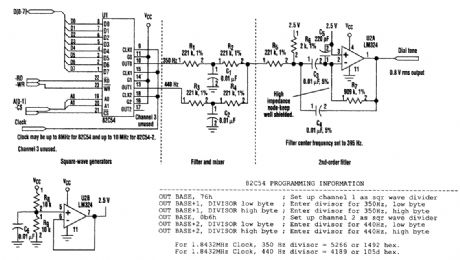
This circuit uses inexpensive, common components to generate a precise dial tone for phone applications (see the figure). U1 (an Intel 82C54 timer-counter) generates 350- and 440-Hz square waves that are filtered by R1/C1 and R3/C2, and mixed together by resistors R2 and R4.An operational amplifier configured as a 395-Hz, Sallen-Key, second-order bandpass filter (halfway between 350 and 440 Hz) removes unwanted signal harmonics. Almost any timer-counter can be used as the signal source, so long as it produces roughly square-wave outputs. (View)
View full Circuit Diagram | Comments | Reading(1765)
PHONE_PAGER
Published:2009/6/22 22:42:00 Author:May
This pager allows you to use your in-house phone wiring as a PA system. It uses two tone decoders to detect a particular touch-tone key. This key enables an audio amplifier. (View)
View full Circuit Diagram | Comments | Reading(2310)
TELEPHONE_SCRAMBLER
Published:2009/6/22 22:38:00 Author:May
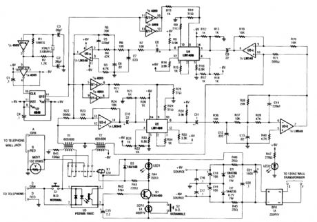
Two hybrids (T1 and T2) are used to allow direct connection to a telephone line. This circuit uses the common speech-in-version algorithm where the frequency of an audio signal is inverted about a center frequency. An LM1496 balanced modulator is used to heterodyne the specch range against a 3.58-kHz signal. (View)
View full Circuit Diagram | Comments | Reading(6)
SPEAKERPHONE_ADAPTER
Published:2009/6/22 22:29:00 Author:May
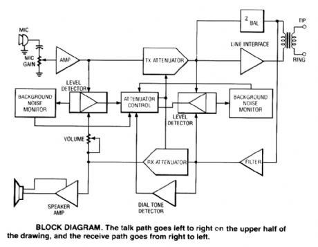
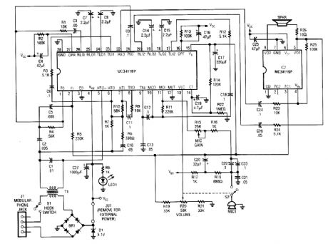
Using a Motorola MC34118 speakerphone IC, this adapter can be used with a regular telephone to provide speaker capability. This device is powered from the phone Iine, but it can be powered via an extemal power supply if the line loop current is marginally low. An external phone is needed for ringing and dialing functions. (View)
View full Circuit Diagram | Comments | Reading(4489)
PHONE_LINE_INTERFACE
Published:2009/6/22 22:26:00 Author:May
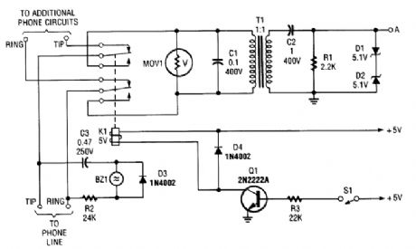
This circuit should be useful for interfacing phone projects to the telephone line. It has a ringer, can interrupt the wiring, and isolates project from the phone line. (View)
View full Circuit Diagram | Comments | Reading(2007)
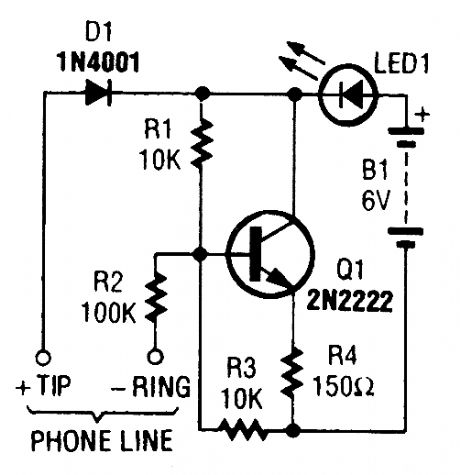
SIMPLE_TELEPHONE_RING_INDICATORLINE
Published:2009/6/22 22:25:00 Author:May
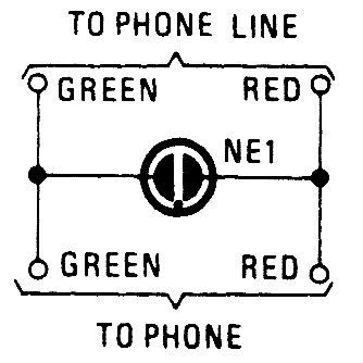
A neon lamp can easily be added to the phone line to act as a ring indicator. It's perfect for times when you can't hear the phone. (View)
View full Circuit Diagram | Comments | Reading(744)
TELEPHONE_BELL_SIMULATOR
Published:2009/6/22 22:24:00 Author:May

This circuit is intended for use in a small private telephone installation. The ringing tone se-quence is 400 ms on, 200 ms off, 400 ms on, 2 ms off. In the accompanying diagram, N1 and N2 form an oscillator that operates at a frequency of 5 Hz, which gives a period of 200 ms. The oscillator signal is fed to two decade sealers, which are connected in such a manner (by N3 and N4) that the in-put signal is divided by 15. The second input of N4 can be used to switch the divider on and off by logic levels. If this facility is not used, the two inputs of N4 should be interconnected. (View)
View full Circuit Diagram | Comments | Reading(764)
PHONE_IN_USE_INDICATOR
Published:2009/6/22 22:18:00 Author:May
This phone-in-use indicator also indicates the presence of a ring signal. Just the thing for the hearing impaired. (View)
View full Circuit Diagram | Comments | Reading(0)
TELEPHONE_RING_CONVERTER
Published:2009/6/22 22:17:00 Author:May
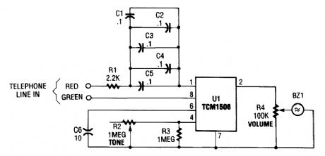
The circuit is based on the TCM1506 ring detector/driver integrated circuit. It is a monolithic IC specifically designed to replace the telephone's mechanical bell. The chip is powered and activated by the telephone-line ring, which can vary from 40 to 150 V rms at a frequency of from 15 to 68 Hz. No other source of power is required. Again, referring to the figure shown, C1 through C5 are placed in parallel to form a 0.5-μF capacitor that conducts the ac ring voltage to pin 1 of the TCM1506, but blocks any dc component. Of course, those capacitors can be replaced by a single 0.47- to 0.5-μF capacitor provided that it has at least a 400-WVdc rating. Resistor R1 is in series with the capacitor network and is used to dissipate power from any high-voltage transient that might appear across the line. The diluted ac voltage that reaches pin 1 on U1 powers the chip.Capacitor C6 is used to prevent bell tapping. That is an annoying ringing of the bell that occurs when a phone on the same line is used to dial an outgoing call. The capacitor prevents the short dial pulses from triggering the ring detector, but still allows the much longer ring signal to activate it.Potentiometer R2 is used to vary the tone of the ring signal from below 100 Hz to over 15 kHz. Potentiorneter R4 is the volume control; adjusting that potentiometer to its lowest resistance will mute the piezo element (BZl). When a ring signal is present on the phone-line, it powers U1. The IC then generates a tone (with a frequency that is determined by R2 and an amplitude set by R4) that is reproduced by BZ1. (View)
View full Circuit Diagram | Comments | Reading(1209)
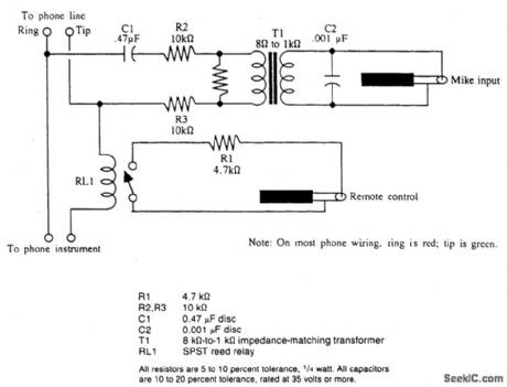
AUTOMATIC_TELEPHONE_CALL_RECORDING_CIRCUIT
Published:2009/6/22 22:11:00 Author:May
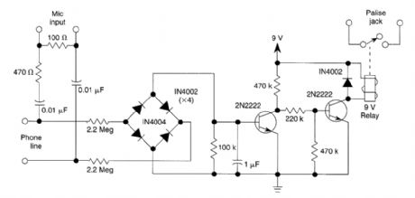
The dc voltage present on a telephone line is usually around 45 to 50 V on-hook and 6 V off-hook. This circuit uses this drop in voltage to activate a relay. The relay controls a cassette tape recorder. Audio is taken off through a network to the microphone input of the cassette. (View)
View full Circuit Diagram | Comments | Reading(1748)
| Pages:5/6 123456 |
Circuit Categories
power supply circuit
Amplifier Circuit
Basic Circuit
LED and Light Circuit
Sensor Circuit
Signal Processing
Electrical Equipment Circuit
Control Circuit
Remote Control Circuit
A/D-D/A Converter Circuit
Audio Circuit
Measuring and Test Circuit
Communication Circuit
Computer-Related Circuit
555 Circuit
Automotive Circuit
Repairing Circuit