
Telephone-Related Circuit
Index 4
PULSE_DIALING_TELEPHONE
Published:2009/7/7 21:36:00 Author:May

The TP5700 or TP5710 can reduce the number of components required to build a pulse-dialing telephone, as shown. The usual current source can be eliminated by using the VREG1 output to power a TP50982A low-voltage (1.7 V) pulse dialer via a blocking diode. A low forward-voltage drop diode such as a Schottky type is necessary because VREG1 is used in its nonregulated mode and its output voltage might fall to 2 V on a 20-mA loop. A 100-μF decoupling capacitor is required to hold up the pulse dialer supply voltage during dialing. This capacitor will take about one second to charge up when the telephone is first connected to the line, but thereafter, the 20-MΩ resistor, required to retain the last-number dialed memory, will keep this capacitor charged. Partial muting is obtained by directly connecting the N-channel opendrain mute output of the pulse dialer to the RCV in pin on the speech circuit. A fully muted pulse dialer design requires the use of a shunt-mode dialer, such as the TP50981A or TP50985A. (View)
View full Circuit Diagram | Comments | Reading(3264)
TONE_DIALING_TELEPHONE
Published:2009/7/7 21:11:00 Author:May
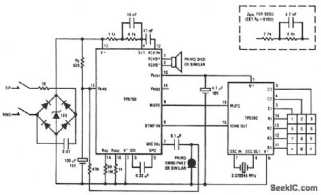
This circuit shows the TP5700 directly interfacing to a low-voltage DTMF generator.VREG1 supplies the necessary 2-V minimum bias to enable the TP5380 to sense key closures and pull its mute output high.VREG1 then switches to a 3-V regulated output to sustain the tone dialer during tone generation. The TP5700 DTMF input incorporates the necessary load resistor to V- and provides gain, plus AGC action, to compensate for loop length. A muted tone level is heard in the receiver. For DTMF generators with a higher output level than the TP5380, a resistive potentiometer should be added to reduce the level at the speech circuit DTMF input. (View)
View full Circuit Diagram | Comments | Reading(4602)
HANDS_FREE_TELEPHONE
Published:2009/7/7 20:55:00 Author:May
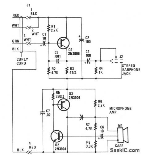
Transistor Q1 of the headset amplifier circuit amplifies the 30 mV signal, that would have gone to the earphones, to.5 V, which sufficiently drives the stereo earphones. Capacitor C1 blocks any dc current from shorting back into the telephone base. Capacitor C2 provides the very important ac signal short around the amplifier. Capacitor C3 provides high-frequency rolloff characteristics and prevents the amplifier from oscillating. Capacitor C4 is a dc block to the 35-Ω impedance of the stereo earphones, and resistor R4 bleeds off any charge build up to prevent a popping sound when the stereo earphones are plugged into the mini-earphone jack J2. The headset amplifier has only about 2 Vdc across it. The microphone amplifier circuit is composed of transistors Q2 and Q3 in an inverted-Darlington configuration.Another, and perhaps easier, way to understand the operation of this circuit is to consider Q3 as an emitter-follower stage. The electret microphone has a built-in FET IC amplifier that needs at least 3 V at 0.4 mA of clean supply power in order to provide an output impedance of 200 to 800 Ω. Resistors R6 and C5 provide that clean dc power to the FET IC and also provide the bias to Q2 without an ac feedback, which would have reduced Q2's gain. Capacitor CG blocks the output dc bias from the FET IC. (View)
View full Circuit Diagram | Comments | Reading(1118)
SPEECH_NETWORK
Published:2009/7/6 20:49:00 Author:May
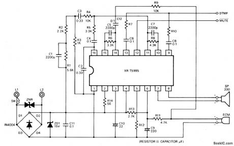
The XR-T5995 Speech Network is a monolithic integrated circuit specifically designed for implementing a low cost telephone circuit. It is designed to use an electrodynamic microphone and electromagnetic receiver to replace a carbon microphone and telephone network hybrid.
(View)
View full Circuit Diagram | Comments | Reading(6409)
TELEPHONE_HOLD_BUTTON
Published:2009/7/6 20:39:00 Author:May

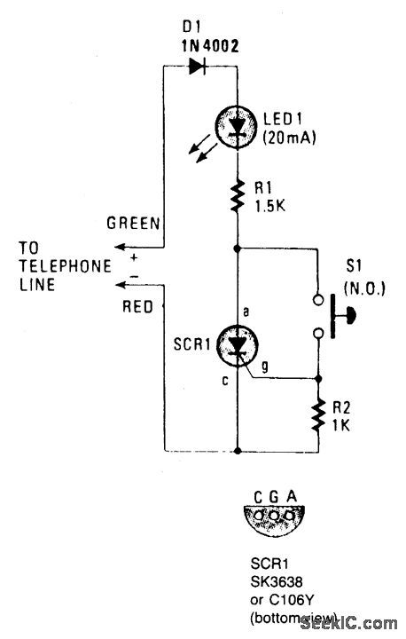
The on-hook (no load) voltage across the red-green wires will be 48 V or slightly less when all telephones are on-hook (disconnected). When any telephone goes off-hook the load current flowing in the telephone causes the voltage to fall below 5 volts dc.Although the telephone hold is connected across the red-green wires, silico1i control rectifier SCR1 is open; so there is no current path across the telephone line. To hold the call, depress normally-open switch S1 and hang up the telephone (still depressing S1). When the phone goes on-hook the red-green voltage jumps to 48 volts dc. Since switch S1 is closed, a positive voltage is applied to SCR1's gate, which causes SCR1 to conduct, thereby completing the circuit across the telephone line through D1, LED1, R1, and SCR1. The current that flows through those components also causes the LED to light up-indicating that the telephone line is being held. The effective load across the red-green wires is the 1500 ohm value of R1, which is sufflcient to seize the line while limiting the current through the LED to a safe value. When the telephone, or an extension, is once again placed off-hook the red-green voltage falls to 5 volts or less.But diode D1 has a normal voltage drop-called the breakover voltage-of 0.7 volts, and the LED has a forward drop of 2.0 volts. Excluding the voltage drop across R1 there is a maximum of 2.3 volts available for SCR1, which is too low to maintain conduction; so SCR1 automatically opens the hold circuit when any telephone goes off-hook. (View)
View full Circuit Diagram | Comments | Reading(95)
PLUG_IN_REMOTE_TELEPHONE_RINGER
Published:2009/7/6 20:37:00 Author:May
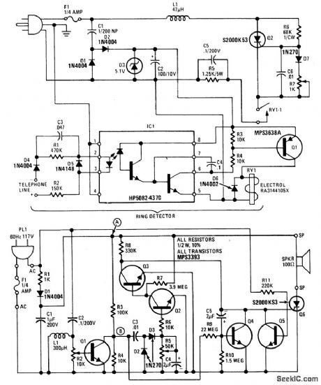
This device consists of a ring detector connected to the telephone line. When the telephone rings, the ring detector impresses high-frequency pulses on the ac power line.A receiver placed anywhere on the same power line detects these pulses and emits an audible tone in synchronization with the telephone signal. (View)
View full Circuit Diagram | Comments | Reading(1153)
HIGH_ISOLATION_TELEPHONE_RINGER
Published:2009/7/6 20:33:00 Author:May
The diode rectifies the ringing signal to supply the operating power to the audio relaxation oscillator made up of L1, L2, R1, R2, and C. Moreover, L2 together with Q1 acts as an opto-isolator, totally isolating the telephone line from the rest of the circuit.The oscillator audio frequency is optically coupled to the photo-Darlington which drives Q2 and thus the speaker. The 10 μF capacitor is not large enough to smooth the ringing ripple completely. This results in frequency modulation of the audio oscillator giving it an attention-getting warble.
(View)
View full Circuit Diagram | Comments | Reading(758)
PHONE_LIGHT
Published:2009/7/6 20:32:00 Author:May
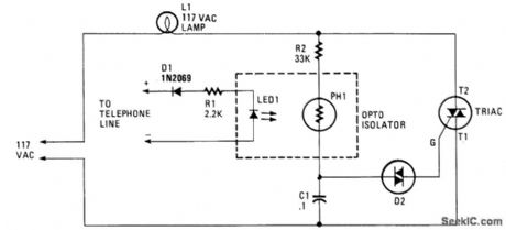
When the phone does ring the triac is triggered into conduction by a signal applied to its gate (G) through a bilateral switch (diac), D2. The triac acts as a switch, conducting only when a signal is present at the gate.
(View)
View full Circuit Diagram | Comments | Reading(910)
CIRCUIT_MONITORS_BLINKING_PHONE_LIGHTS
Published:2009/7/6 20:31:00 Author:May
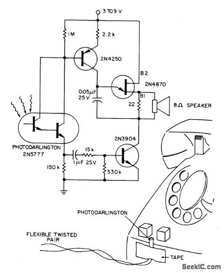
A 2N5777 photo-Darlington cell picks up blinking light from the transparent plastic buttons. The power is switched ON and OFF by a hibeta 2N3904 transistor. The circuit's 9 V battery can be left continuously connected. Less than a microampere is drawneven with normal, office ambient light and the phone lights not flashing. For noisy locations, the tone can be made louder with an output transformer (ratio of 250:8) or a 100 ohm speaker that replaces the 22 ohm resistor in the output. (View)
View full Circuit Diagram | Comments | Reading(1764)
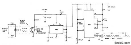
TELEPHONE_RINGING_DETECTORFREQUENCY_AND_VOLUME_CONTROLLED
Published:2009/7/6 20:28:00 Author:May
With the 555 timer connected as a multivibrator and an opto-isolator, a remote speaker can be driven. (View)
View full Circuit Diagram | Comments | Reading(823)
AUTOMATIC_TELEPHONE_RECORDING_DEVICE
Published:2009/7/6 20:27:00 Author:May
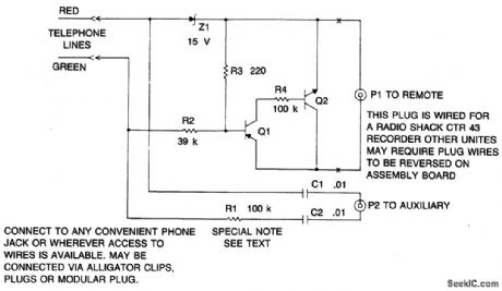
The device is a dc switch that is normally on via the forward biasing of Q1 via R3.Q1 now clamps Q2 into a forward state by biasing its complement well into a saturated state via R4. The dc switch is turned off via a negative voltage above that of the zener (D1). This voltage is usually about 48 and is the on-hook value of the phone line. This negative voltage overrides the effect of R3 and keeps the circuit off. When the phone is off the hook, the 48 vblts drops to 10 volts, that is below the zener voltage of D1 and R3 now tums the circuit on. The audio signal is via attenuator resistor R1 and dc isolating capacitors C1, C2. The device is a high impedance switch that isolates the recording controlled device from the phone line via some relatively simple electronic circuitry. It requires no battery and obtains power for operating via the remote jack that in most recorders is a source of 6 volts. When clamped to ground it initiates recorder operation. The unit interfaces with most portable cassette recorders providing they contain a remote control jack.
(View)
View full Circuit Diagram | Comments | Reading(858)
DUAL_TONE_DECODING
Published:2009/7/6 20:26:00 Author:May
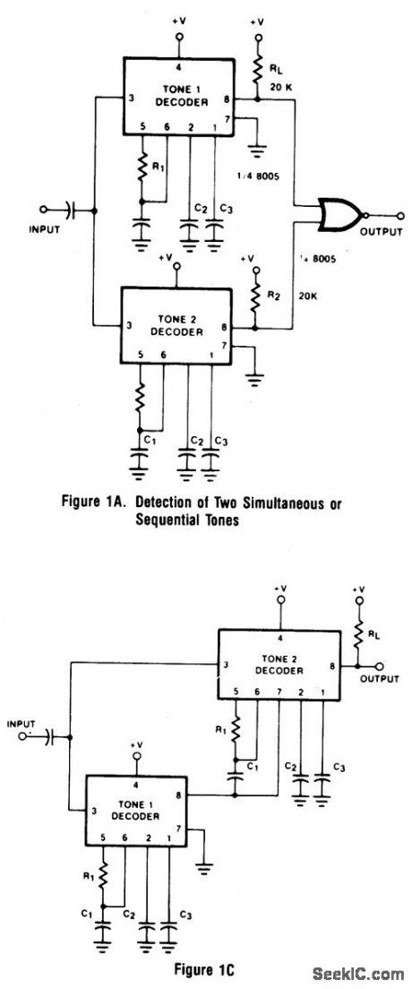
Two integrated tone decoders, XR-567 units, can be connected (as shown in Fig.1A) to permit decoding of simultaneous or sequential tones. Both units must be on before an output is given. RIC1 and R'1C'1 are chosen, respectively, for Tones 1 and 2. If sequential tones (1 followed by 2) are to be decoded, then C3 is made very large to delay turn-off of Unit Luntil Unit 2 has turned on and the NOR gate is activated. Note that the wrong sequence (2 followed by 1) will not provide an output since Unit 2 will turn off before Unit 1 comes on. Figure 1B shows a circuit variation which eliminates the NOR gate. The output is taken from Unit 2, but the Unit 2 output stage is biased off by R2 and CR1 until activated by Tone 1. A further variation js given in Fig. IC.Here, Unit 2 is turned on by the Unit 1 output wh.en Tone 1 appears, reducing the standby power to half. Thus, when Unit 2 is on, Tone 1 is or was present. If Tone 2 is now present, Unit 2 comes on also and an output is given. Since a transient output pulse may appear at Unit 1 turn-on, even if Tone 2 is not present, the load must be slow in response to avoid a false output due to Tone 1 alone. The XR-267 Dual Tone Decoder can replace two integrated tone decoders in this application.
(View)
View full Circuit Diagram | Comments | Reading(839)
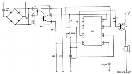
ELECTRONIC_PHONE_BELL
Published:2009/6/25 22:40:00 Author:May
The speaker emits a distinctive warble tone when ring pulses are applied to the phone line. Use this circuit as a remote bell or discon-nect the phone's ringer for direct use. R1 ad-justs the duration of the output; R2 and R3 control the tone's duty cycle and frequency. The transistor is a general-purpose NPN photodevice. The neon bulb and transistor are coupled with the heat-shrink tubing to form an optoisolator. (View)
View full Circuit Diagram | Comments | Reading(846)
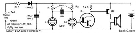
TELEPHONE_RINGER_USES_PIEZOELECTRIC_DEVICE
Published:2009/6/25 22:39:00 Author:May
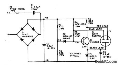
The electronic bell needs no power sup-ply. Most of the resistors are not critical, al-though C2, R2, and R3 work best at the values given. Leaving out RI will make the unit ring louder. The piezo buzzer may vary from store to store. If it has two leads, connect the red lead to the collector and the black lead to the emit-ter of Q1. If a third (blue) lead is present, connect it to the base of Q1. (View)
View full Circuit Diagram | Comments | Reading(863)
AUTOPATCH_TELEPHONE_LINE_INTERFACE
Published:2009/6/25 22:38:00 Author:May
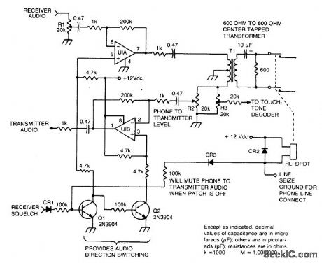
This circuit provides for the receiver-to-phone line and phone line-to-transmitter link, with both using an op amp for gain. (View)
View full Circuit Diagram | Comments | Reading(1808)
PHONE_AUTO_ANSWER_AND_RING_INDICATOR
Published:2009/6/25 22:37:00 Author:May

Ring detect circuit for automatic phone answering or tone generation for reverse autopatch use. (View)
View full Circuit Diagram | Comments | Reading(1404)
LOW_LINE_LOADING_RING_DETECTOR
Published:2009/6/25 22:36:00 Author:May

Low line current loading is provided by the H11BX522 photodarlington op-tocoupler, which provides a 1 mA output from a 0.5 mA input. (View)
View full Circuit Diagram | Comments | Reading(669)
TELEPHONE_HANDSET_TONE_DIAL_ENCODER
Published:2009/6/25 22:35:00 Author:May


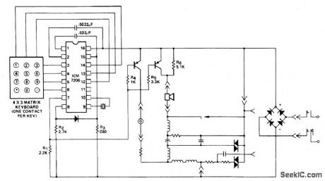
This encoder uses a single contact per key keyboard and provides all other switching func-tion electronically. The diode between termi-nals 8 and 15 prevents the output going more than 1 volt negative tive supply V-. The supply voltage range with respect to the nega-circuit operates over the from 3.5 volts to 15 volts. (View)
View full Circuit Diagram | Comments | Reading(921)
TELEPHONE_LINE_MONITOR
Published:2009/6/25 22:06:00 Author:May
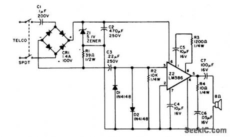
Using rectified audio as a power supply, this monitor will send the telephone line audio into an 8 ohm speaker. (View)
View full Circuit Diagram | Comments | Reading(132)
TELEPHONE_OR_EXTENSION_TONE_RINGER
Published:2009/6/25 22:06:00 Author:May
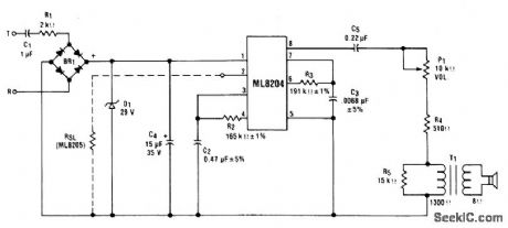
This circuit uses ML8204/ML8205 devices. With the components shown, theoutput frequency chops between 512 Hz (fH1) and 640 Hz (fH2) at a10 Hz (fL) rate. (View)
View full Circuit Diagram | Comments | Reading(1986)
| Pages:4/6 123456 |
Circuit Categories
power supply circuit
Amplifier Circuit
Basic Circuit
LED and Light Circuit
Sensor Circuit
Signal Processing
Electrical Equipment Circuit
Control Circuit
Remote Control Circuit
A/D-D/A Converter Circuit
Audio Circuit
Measuring and Test Circuit
Communication Circuit
Computer-Related Circuit
555 Circuit
Automotive Circuit
Repairing Circuit