
Electrical Equipment Circuit
Index
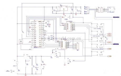
Audi A6 Radio Schematic
Published:2014/4/20 20:42:00 Author:lynne | Keyword: Audi A6 Radio Schematic
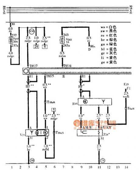
Audi A6 Radio Schematic shown as follow:
(View)
View full Circuit Diagram | Comments | Reading(2384)
Pump motor automatic switching circuit
Published:2013/4/6 22:28:00 Author:Ecco | Keyword: Pump motor automatic switching
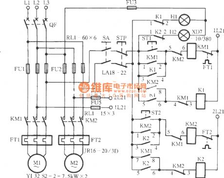
Pump motor automatic switching circuit is shown as figure.
(View)
View full Circuit Diagram | Comments | Reading(3750)
Electronics Attenuator electronic circuit
Published:2013/4/1 3:14:00 Author:Ecco | Keyword: Electronics Attenuator
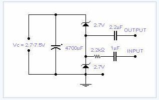
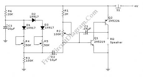
Two low voltage, low power zeners are used to control electronically the level of an audio signal. The attenuation range is from 6 to 58dB for an input current from 0.042 to 77 mA corresponding to a control voltage from 2.7 to 7.5V. If control voltage is limited to 5V, the attenuation is around 30dB at a control current of 2mA. This is not an HiFi attenuator but might come useful as a general purpose audio attenuator.
(View)
View full Circuit Diagram | Comments | Reading(2326)
Capacitor ESR Meter circuit
Published:2013/3/29 4:25:00 Author:Ecco | Keyword: Capacitor ESR Meter
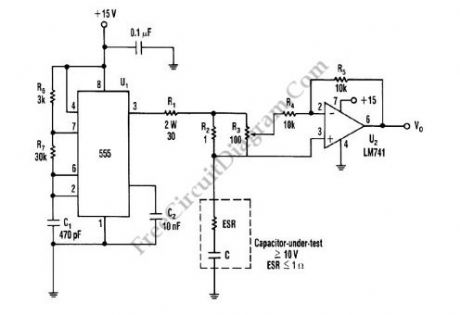
This is schematic diagram of capacitor ESR meter circuit. ESR is equivalent series resistance, and this parameter is used to express the resistance value of any electronic component that basically is not a resistor. ESR is present on many non-resistor component, such as capacitor, inductor, or semiconductor. The circuit shown in this schematic diagram is used to measure equivalent series resistance (ESR) of a capacitor. This ESR meter circuit uses 555 IC as 50-kHz square-wave generator. The ±180mA current waveform is driven in the capacitor-under-test by U1, through R2 and R1. Adjust R3 to the proper value, the inverting amplifier (U2) will null the voltage drop across the equivalent series resistor. The minimum voltage that can be produced at VO the pure capacitor voltage. Here is the schematic diagram of the circuit:
(View)
View full Circuit Diagram | Comments | Reading(9302)
Discrete Sliding Tone (Frequency Ramp) Doorbell circuit
Published:2013/3/28 4:06:00 Author:Ecco | Keyword: Discrete Sliding Tone , Doorbell
This doorbell circuit produces a low tone that will slide up to higher frequency. The equivalent total resistance connected between the base of Q1 and ground (Rbg) , and coupling capacitor C1 determines the AF oscillator’s frequency. The resistance (Rbg) is equal to (R2+R1)R3. Here is the schematic diagram of the circuit:
(View)
View full Circuit Diagram | Comments | Reading(2803)
The audible Logic Probe/Indicator
Published:2013/3/28 3:51:00 Author:Ecco | Keyword: Audible Logic Probe, Indicator
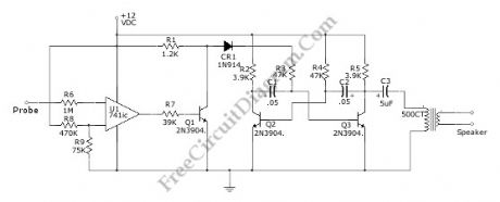
Logic indicator circuit / logic probe is used to identify logic level at any point of logic circuitry. The indicator can be visual (using LED, LCD, of 7 Segments) or auditory (using beeper or speaker). This circuit has a audible indicator, with the help of a loudspeaker to produce indication tone. Using the opamp,U1, as schmitt trigger, the Audio oscillator Q3-Q1-Q2 is isolated from TTL. Beside that, the op amp also acts as high input impedance inverter. The R8-R9 is used to set reference level at +16.6V which is a midway between low and high logic level. The Q3-Q2 will generate tone that indicate a high logic when the probe voltage is above +1.6V. If the probe voltage is below +1.6V then the OP-amp output will saturate the Q1 and disables Q3-Q2 to cut off tone. Here is the schematic diagram of the circuit:
(View)
View full Circuit Diagram | Comments | Reading(2907)
Miniature Black and White TV System
Published:2013/3/10 22:52:00 Author:Ecco | Keyword: Miniature Black , White TV System

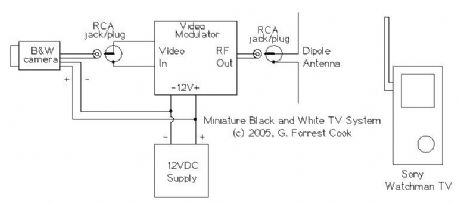
The camera's video signal is connected to the video modulator with an RCA jumper cable. Power to the camera and video modulator is connected to the 12V power supply. Be careful with polarity, reversing the leads may damage the modulator. The camera that was used had reverse polarity protection built in. The modulator's RF output signal is connected to a small antenna, the antenna can be made with two short lengths of #16 gauge solid wire. Alternately, for long distance wired operation, the RF signal can be fed into a length of 75 ohm coax cable with a 75 ohm terminating resistor across the far end of the cable. Connect the remote center conductor of the cable to the TV antenna through a 330 ohm resistor.
(View)
View full Circuit Diagram | Comments | Reading(2684)
Massage schematic SCH
Published:2013/3/7 2:21:00 Author:Ecco | Keyword: Massage schematic SCH
Massage schematic SCH is shown as figure.
(View)
View full Circuit Diagram | Comments | Reading(4289)
AUTOMATIC CURTAIN CLOSER Circuit
Published:2013/3/4 21:28:00 Author:Ecco | Keyword: AUTOMATIC, CURTAIN CLOSER
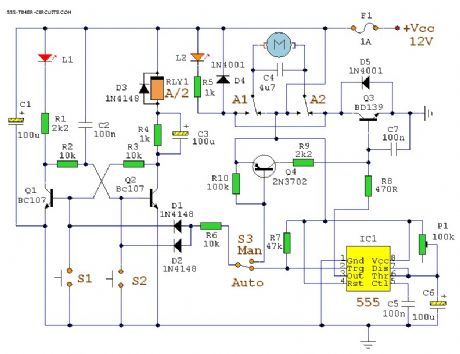
This circuit uses a mixture of transistors, an IC and a relay and is used to automatically open and close a pair of curtains. Using switch S3 also allows manual control, allowing curtains to be left only partially open or closed. The circuit controls a motor that is attached to a simple pulley mechanism, to move the curtains. Automatic OperationThe circuit can be broken into three main parts; a bi-stable latch, a timer and a reversing circuit. Toggle switch S3 determines manual or automatic mode. The circuit as shown above is drawn in the automatic position and operation is as follows. The bi-stable is built around Q1 and Q2 and associated circuitry and controls relay A/2. S1 is used to open the curtains and S2 to close the curtains. At power on, a brief positive pulse is applied to the base of Q2 via C2. Q2 will be on, and activate relay A/2.The network of C3 and R4 form a low current holding circuit for the relay. Relay A/2 is a 12V relay with a 500 ohm coil. It requires slightly less current to keep it energized than it does to operate it. Once the relay has operated, the current through the coil is reduced by R4, saving power consumption. When Q2 is off, C3 will be discharged, but when Q2 becomes active (either at switch-on or by pressing S1) capacitor C3 will charge very quickly via the relay coil. The initial charging current is sufficient to energize the relay and current flow through R4 sufficient to keep it energized.
(View)
View full Circuit Diagram | Comments | Reading(3329)
Oxygen circuit
Published:2013/3/4 3:11:00 Author:Ecco | Keyword: Oxygen
Oxygen circuit is shown as figure.
(View)
View full Circuit Diagram | Comments | Reading(3146)
tda1521 produced 2.1 computer subwoofer speaker circuit diagram
Published:2013/2/18 0:43:00 Author:Ecco | Keyword: computer subwoofer speaker
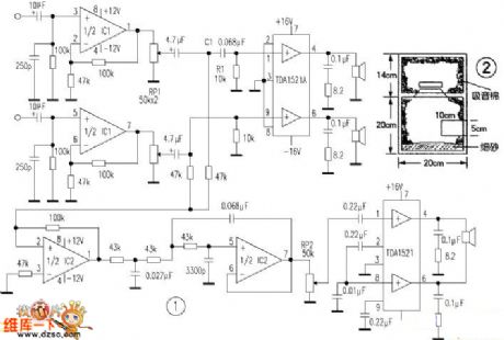
This circuit uses a tda1521 as a two-channel power amplifier, and another tda1521 btl output is used as subwoofer amplifier. ic1 and ic2 may use the ne5532, jrc4558 or tl082. You can also use other high-end op amp such as op275, lt1057, opa2604, etc. But for computer speaker, the ordinary op put is enough.
(View)
View full Circuit Diagram | Comments | Reading(15222)
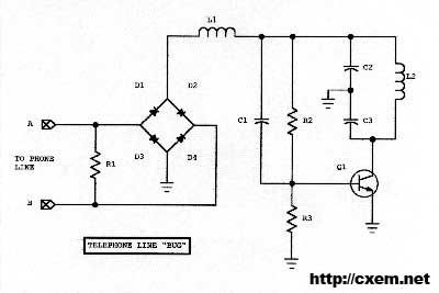
wireless telephone bug
Published:2013/2/17 20:34:00 Author:muriel | Keyword: wireless telephone bug
View full Circuit Diagram | Comments | Reading(3377)
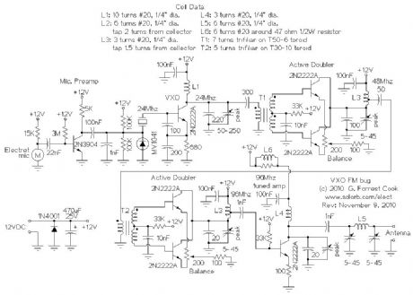
VXO FM Bug
Published:2013/2/17 20:33:00 Author:muriel | Keyword: VXO FM Bug
View full Circuit Diagram | Comments | Reading(2897)
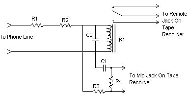
Simple Phone Tap 2
Published:2013/2/17 20:31:00 Author:muriel | Keyword: Simple Phone Tap
View full Circuit Diagram | Comments | Reading(2373)
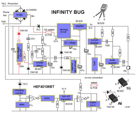
Infinity Bug 2
Published:2013/2/17 20:30:00 Author:muriel | Keyword: Infinity Bug
View full Circuit Diagram | Comments | Reading(2490)
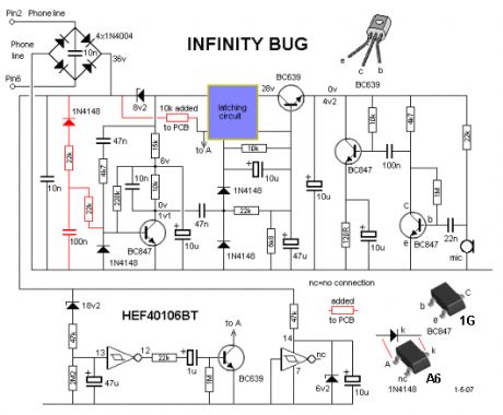
Infinity Bug 1
Published:2013/2/17 20:29:00 Author:muriel | Keyword: Infinity Bug
View full Circuit Diagram | Comments | Reading(2252)
FM Telephone Bug 2
Published:2013/2/17 20:28:00 Author:muriel | Keyword: FM Telephone Bug
View full Circuit Diagram | Comments | Reading(1937)
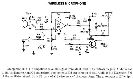
wireless microphone
Published:2013/2/17 20:27:00 Author:muriel | Keyword: wireless microphone
View full Circuit Diagram | Comments | Reading(0)
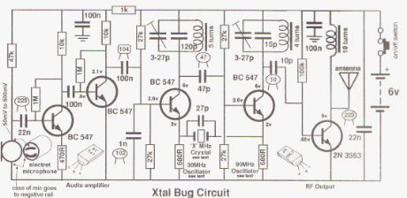
CRYSTAL LOCKED FM BUG
Published:2013/2/17 20:22:00 Author:muriel | Keyword: CRYSTAL LOCKED, FM BUG
View full Circuit Diagram | Comments | Reading(3175)
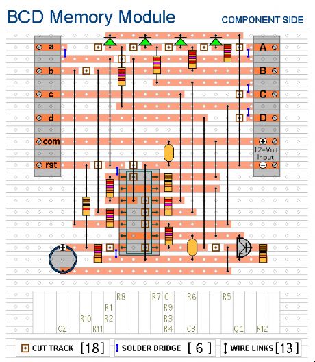
BCD Keypad Module 2
Published:2013/2/17 19:59:00 Author:muriel | Keyword: BCD Keypad Module
View full Circuit Diagram | Comments | Reading(2515)
| Pages:1/126 1234567891011121314151617181920Under 20 |
Circuit Categories
power supply circuit
Amplifier Circuit
Basic Circuit
LED and Light Circuit
Sensor Circuit
Signal Processing
Electrical Equipment Circuit
Control Circuit
Remote Control Circuit
A/D-D/A Converter Circuit
Audio Circuit
Measuring and Test Circuit
Communication Circuit
Computer-Related Circuit
555 Circuit
Automotive Circuit
Repairing Circuit