
Electrical Equipment Circuit
Index 5
Simple water detector circuits
Published:2012/9/24 4:07:00 Author:muriel | Keyword: water, detector

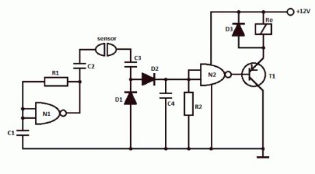
This simple water detector circuit uses alternative voltage in order to prevent the corrosion of the electrodes. It is easy to build and uses N1 as a trigger Schmitt gate which generate the AC. If between the electrodes is a electricity conductor, for example an aqueous solution, then because of the rectification action of D1 and D2, the C4 capacitor is charging.When the capacitor voltage reaches switching threshold of the N2 trigger Schmitt, the relay will trigger and connect, for example a drain pump. The pump will be disconnected as soon as the electrodes won’t touch the liquid.
Simple water detector circuit schematic
Water detector componentsR1 = 470KR2 = 10M … 22MC1 … C4 = 2.2nFN1, N2 = 1/2 4093D1 … D3 = 1N4148T1 = pnp transistor (BC557)?
10 Responses to “Simple water detector circuit”
(View)
View full Circuit Diagram | Comments | Reading(1553)
Simple water detector circuit
Published:2012/9/24 4:06:00 Author:muriel | Keyword: water, detector
This simple water detector circuit uses alternative voltage in order to prevent the corrosion of the electrodes. It is easy to build and uses N1 as a trigger Schmitt gate which generate the AC. If between the electrodes is a electricity conductor, for example an aqueous solution, then because of the rectification action of D1 and D2, the C4 capacitor is charging.When the capacitor voltage reaches switching threshold of the N2 trigger Schmitt, the relay will trigger and connect, for example a drain pump. The pump will be disconnected as soon as the electrodes won’t touch the liquid.
Simple water detector circuit schematic
Water detector componentsR1 = 470KR2 = 10M … 22MC1 … C4 = 2.2nFN1, N2 = 1/2 4093D1 … D3 = 1N4148T1 = pnp transistor (BC557)?
10 Responses to “Simple water detector circuit”
(View)
View full Circuit Diagram | Comments | Reading(292)
Sound Level Meter Circuit
Published:2012/9/24 4:04:00 Author:muriel | Keyword: Sound, Level Meter
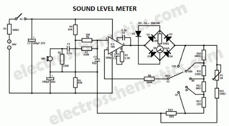
This sound level meter circuit can be used to control the intensity of a sound recording or in a disco. It has 5 measurement domains between 70 and 120 dB; reading accuracy is 0.5 dB. Microphone M1 is used to receive the acoustic signal and is coupled to C1, C2, R1 and R2. This components, together with the microphone’s capacity and with the input impedance of the amplifier form an input filter. The filtered signal goes to operational amplifier IC1 whose sensitivity can be switched with S2 corresponding to the five measuring domains.D1 … D4 diodes rectifies the alternating voltage at the amplifier output and feeds the indicator tool through R9. D5 is used in order to protect the sound level meter indicator against high voltages; it limits the rectifier’s output voltage when the sound level is too high.
On normal conditions the input current is about 2 mA that is why the circuit can be powered with 2 x 9V batteries. S1 switch is used to disconnect the sound level meter device after measurement. The indicator tool should have a graded scale in dB with the maximum value of +10.
Sound Level Meter Schematic
?
4 Responses to “Sound Level Meter Circuit”
(View)
View full Circuit Diagram | Comments | Reading(2368)
Small FM Radio Circuit
Published:2012/9/20 20:56:00 Author:Ecco | Keyword: Small FM Radio
Perhaps this is one of the simplest and smallest FM radio receiver that can receive the FM stations available locally. Its simple design makes it ideal for a pocket sized FM receiver. The output of the receiver drives a head phone.
Tiny FM Radio Receiver Circuit Schematic
The circuit works off a small 4.5 volt battery or two 3.6 volt Lithium button cells.The fm receiver section has two RF transistors T1 and T2 to detect the Frequency Modulated signals. Coil L1 and the trimmer capacito form the tuned tank circuit to tune the receiver to the best FM station with strong signals. The signals are capacitor coupled through C2.
10K preset VR controls the volume to the input of the amplifier. IC1 is the micro power audio amplifier that works between 4.5 to 12 volts DC. The amplified sound can be heard through the low impedance head phone or small Mylar speakers.
FM radio coilCoil is the important part of the FM tuner. It is made up of 18 SWG enameled copper wire. Wind 4 turns on a ball pen to get 0.5 cm inner diameter. Remove the enamel from the tip of the wire and solder tightly in the PCB. Trimmer and coil should be soldered very closely. Adjust the spacing of the coil winding if necessary to get the station clearly. Assemble all the receiver components as close as possible to get better result.
Pinout of BF494 and LM386
?
33 Responses to “Small FM Radio Circuit”
Source: electroschematics.com
(View)
View full Circuit Diagram | Comments | Reading(2887)
Smart Cooling Fan Circuit
Published:2012/9/19 21:41:00 Author:Ecco | Keyword: Smart , Cooling Fan
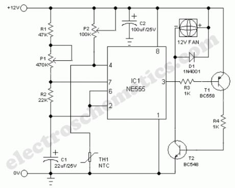
A continuously running cooling fan is a big nuisance and is not very crucial in most instruments. The 12V smart fan control presented here allows the fan to run at rates varying from once a second to once in ten seconds approximately. In case of a battery powered instrument, this idea will save some power too!Basically, the cooling fan circuit is an astable multivibrator built around NE555(IC1), in which the output level at pin 3 remains high for a long time and low for a short time. The low level output at pin 3 drives the cooling fan via T1 and T2. This timeout (delay) period can be adjusted using preset pot P1.A simple temperature detector mechanism is deliberately added to the main circuit. Here, a negative temperature coefficient (NTC) type thermistor (TH1) functions as the heat monitor. Normally the resistance of TH1 is high and the astable is enabled through trimpot P2. When temperature increases beyond a limit set by preset pot P2, the astable is disabled by the grounding of its reset terminal (pin4) via TH1. At this time, output at pin 3 of IC1 remains in low level and the cooling fan sweeps continuously.
Temperature dependent cooling fan schematic
?
11 Responses to “Smart Cooling Fan Circuit”
Source: electroschematic.com
(View)
View full Circuit Diagram | Comments | Reading(2546)
Sleep Aid in case of insomnia
Published:2012/9/18 21:18:00 Author:Ecco | Keyword: Sleep Aid, in case of, insomnia
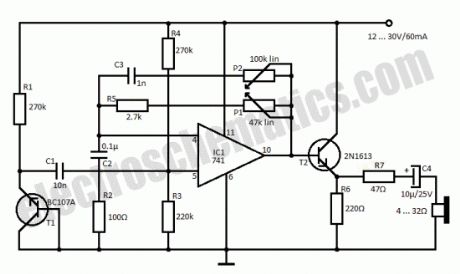
Insomnia treatment consist mostly of sleeping pills consumption but this circuit is an alternative for that and consists of a simple circuit that generates a rain sound effect. The japanese researches were the first to discover that sound of rain has a relaxing effect. With the help of this simple circuit we can generate the rain sound which can be a sleep aid in case of insomnia.T1 is used as a noise generator and its signal is amplified by the 741 IC and thru T2, R7 and C4 goes to a headset with low resistance. If you do not want to use the headphones then use a speaker with impedance between 4 and 16 Ω. With the help of P1 can adjust sound level and with P2 the tone.
Sleep Aid Circuit Schematic
?
5 Responses to “Sleep Aid in case of insomnia”
Source: electroschematics.com
(View)
View full Circuit Diagram | Comments | Reading(2134)
Thermostatical electric radiator circuit using TC621
Published:2012/9/14 2:59:00 Author:Ecco | Keyword: Thermostatical, electric radiator
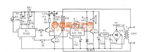
As shown in the circuit, the circuit consists of temperature control switch circuit, SCR trigger control heating circuit, music sound circuit and AC buck rectifier circuit. The circuit has wide temperature control range, simple line, good temperature control, and it does not have mechanical contacts, so it is safe, reliable, easy to set upper and lower limits of temperature. It can be widely used in the family bathroom, livestock, poultry sterile raising room and other occasions.
(View)
View full Circuit Diagram | Comments | Reading(1638)
Water Softener Circuit
Published:2012/9/16 20:50:00 Author:Ecco | Keyword: Water Softener
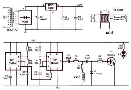
That circuit is based at a technique to remove or neutralize the salt in water, and protect the pipes at home as well as the washing machines or our selves from salt. Its called water softener and its automated circuit using two 555 timers. (View)
View full Circuit Diagram | Comments | Reading(0)
The simplest Electronic Door Lock
Published:2012/9/16 20:37:00 Author:Ecco | Keyword: simplest , Electronic Door Lock
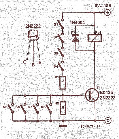
To put the relay in tension the 4 buttons S1 S4 must be pressed. If anyone of the 4 butoons S5 S8 are pushed the relay donts tension ( dont receives supply voltage ). The supply voltage must be equal to the working voltage of the relay. One transistor like BD135 can commute up to 0.5A, in the same tine 2N2222 can do only 0.2A.
(View)
View full Circuit Diagram | Comments | Reading(1505)
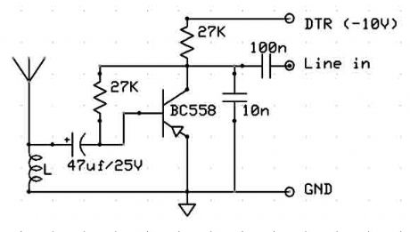
TV and FM jammer schematic
Published:2012/9/13 20:59:00 Author:Ecco | Keyword: TV, FM jammer
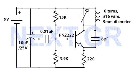
The Jammer is a very small circuit and can fit inside a small plastic box with 9V battery inside. It can be very illegal if you attach an external antenna so don't. adjust frequency by turning trimmer.
Source: NEXT.GR (View)
View full Circuit Diagram | Comments | Reading(0)
FM radio with TDA7000
Published:2012/9/13 20:58:00 Author:Ecco | Keyword: FM radio
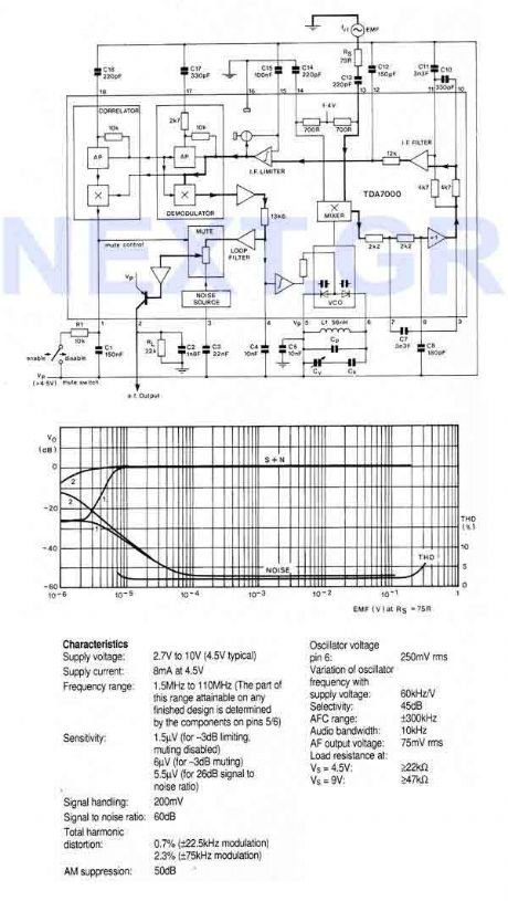
An FM radio on a single chip requiring only a few simple peripheral components. In particular the ship requires only one simple coil and alignment is very easy. The chip includes an RF input stage, mixer, local oscillator, IF amplifier/limiter, phase demodulator, mute detector and mute switch. The output will directly drive a crystal earpiece or could be used with a TBA820M to form a complete portable radio.
Source: NEXT.GR (View)
View full Circuit Diagram | Comments | Reading(2593)
Active Antenna for 10 to 30 MHz
Published:2012/9/13 20:37:00 Author:Ecco | Keyword: Active Antenna , 10 to 30 MHz
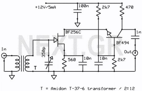
The schematic shown, is a 2 transistor signal amplifier between 10 MHz to 30 MHz. The BF256C and the BF494 are very popular transistors and are easy to find. The transformer works as insulator and amplifier.
Source: NEXT.GR (View)
View full Circuit Diagram | Comments | Reading(2405)
Active Antenna Circuit for 10KHz to 100MHz
Published:2012/9/13 3:52:00 Author:Ecco | Keyword: Active Antenna , 10KHz to 100MHz
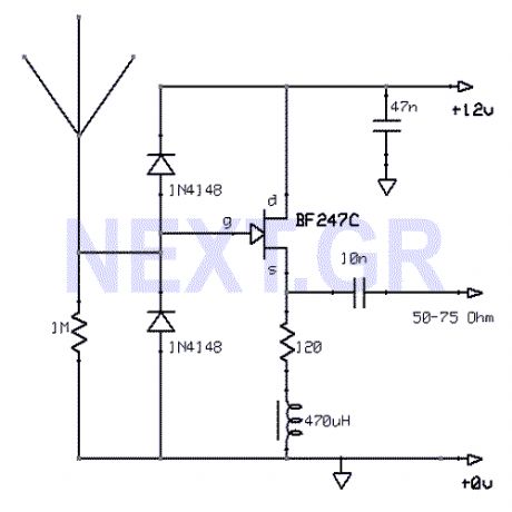
This active antenna schematic can be used to frequency range from 10 KHz to 100 MHz. The length of the Antenna can be between 0.5 to 1 meter long. The power consumption is 20-30mA.
Source: NEXT.GR (View)
View full Circuit Diagram | Comments | Reading(3282)
FSK Demodulator/Tone Decoder with RC2211N
Published:2012/9/13 3:46:00 Author:Ecco | Keyword: FSK, Demodulator, Tone Decoder
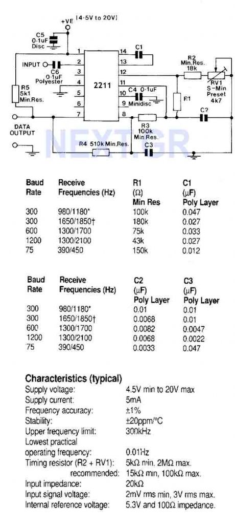
A monolithic phase locked loop for data communications. The IC contains a basic phase locked loop for tracking an input signal within the pass band, a quadrature phase detector which provided carrier detector and an FSK voltage comparator which provides FSK demodulation. In the circuit shown, the IC is used as an FSK demodulator such as would be found in the receiver circuit of a modem.
Source: NEXT.GR (View)
View full Circuit Diagram | Comments | Reading(0)
PAL Colour Encoder (TEA2000-V1)
Published:2012/9/13 3:45:00 Author:Ecco | Keyword: PAL , Colour , Encoder
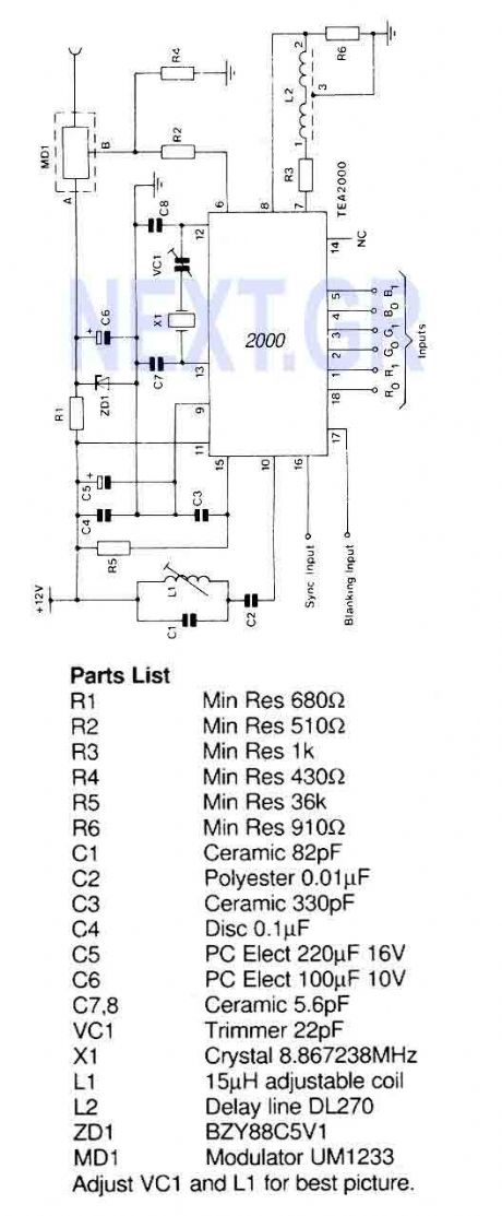
A PAL color encoder and video summer which requires just composite sync and composite blanking inputs, and a 6-bit binary coded input giving the color information. The inputs are organized as 2 bits per primary color with gamma correction automatically applied to the resultant luminance and chrominance levels.
Source: NEXT.GR (View)
View full Circuit Diagram | Comments | Reading(2393)
FM radio with TDA7000
Published:2012/9/12 20:59:00 Author:Ecco | Keyword: FM radio

An FM radio on a single chip requiring only a few simple peripheral components. In particular the ship requires only one simple coil and alignment is very easy. The chip includes an RF input stage, mixer, local oscillator, IF amplifier/limiter, phase demodulator, mute detector and mute switch. The output will directly drive a crystal earpiece or could be used with a TBA820M to form a complete portable radio.
Source: NEXT.GR (View)
View full Circuit Diagram | Comments | Reading(2)
Digital Voice Recorder/Playback (UM5100)
Published:2012/9/12 20:56:00 Author:Ecco | Keyword: Digital , Voice Recorder, Playback
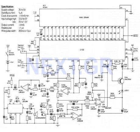
This Circuit is based on the UM5100 which can record speech into a digital memory and then play it back. The device is designed to be used directly with static RAM's up to 256K bits, or with EPROM 's or ROM's for playback only. High quality voice reproduction is possible and note that it is not a computer voice , it is the original speaker's voice played back. The bit rate is adjustable from 10kbs to 28kbs with higher quality at faster bit rates.
Source: NEXT.GR (View)
View full Circuit Diagram | Comments | Reading(2943)
AM reciever with TDA1072A
Published:2012/9/12 20:55:00 Author:Ecco | Keyword: AM reciever
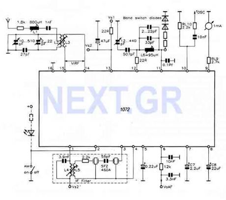
This reciever uses the TDA1072A which is a complete AM reciever on a chip and it only requires comparitively few peripheral components to complete a high quality AM radio Circuit. Unlike some other AM radio ICs, a minimum number of external tuned inductors are used to preserve reasonable performance, selectivity and quality of output. Only two of these, an RF input transformer and a single winding oscillator coil need be tuned either capacitively or inductively.
Source: NEXT.GR (View)
View full Circuit Diagram | Comments | Reading(2416)
Room Ioniser circuit
Published:2012/9/12 20:51:00 Author:Ecco | Keyword: Room Ioniser
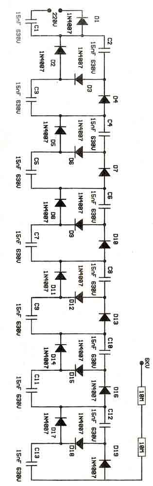
This is a voltage multiplier circuit acting as an Ioniser. Its calculated to feed 220V from mains and the output is about 6KV. Caution should take with the circuit as can be dangerous due to mains. You can place a needle at the output 3cm long. (View)
View full Circuit Diagram | Comments | Reading(2124)
Short wave radio for PC
Published:2012/9/12 20:47:00 Author:Ecco | Keyword: Short wave radio, PC
This Cheap circuit will amaze you with its wide range recieving signal between 6 and 17Mhz (49-19meters). Power supply is not necesery, just connect it to your pc, place the antena to your home piping network and voila! (View)
View full Circuit Diagram | Comments | Reading(5917)
| Pages:5/126 1234567891011121314151617181920Under 20 |
Circuit Categories
power supply circuit
Amplifier Circuit
Basic Circuit
LED and Light Circuit
Sensor Circuit
Signal Processing
Electrical Equipment Circuit
Control Circuit
Remote Control Circuit
A/D-D/A Converter Circuit
Audio Circuit
Measuring and Test Circuit
Communication Circuit
Computer-Related Circuit
555 Circuit
Automotive Circuit
Repairing Circuit