
Electrical Equipment Circuit
Index 12
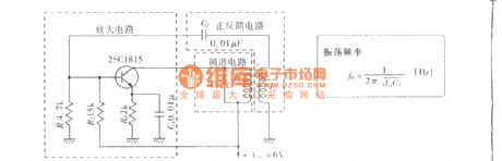
Collector tuned oscillator circuit
Published:2011/11/28 0:58:00 Author:Ecco | Keyword: Collector, tuned oscillator
View full Circuit Diagram | Comments | Reading(1092)
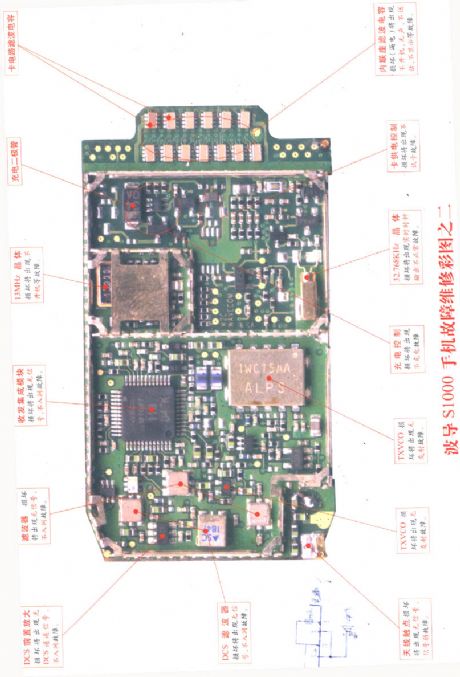
Bird S1000 cellphone repairing diagram 2
Published:2011/11/4 3:15:00 Author:Ecco | Keyword: Bird , cellphone repairing diagram
View full Circuit Diagram | Comments | Reading(1016)
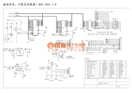
Fax circuit diagram 2
Published:2011/11/11 2:26:00 Author:Ecco | Keyword: Fax circuit
View full Circuit Diagram | Comments | Reading(1302)
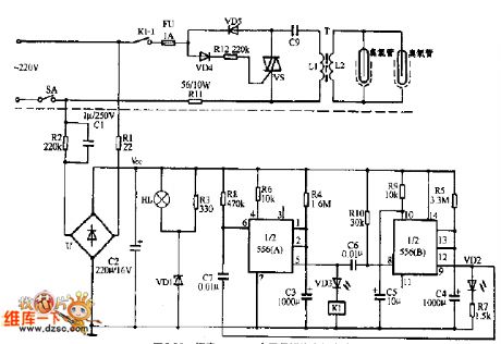
Doorbell circuit
Published:2011/10/18 22:08:00 Author:Ecco | Keyword: Doorbell
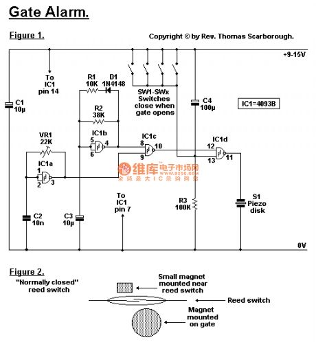
By Rev. Thomas Scarborough Cape Town E-mail scarboro@iafrica.com Figure 1 represents a cheap and simple Gate Alarm, that is intended to run off a small universal AC-DC power supply. IC1a is a fast oscillator, and IC1b a slow oscillator, which are combined through IC1c to emit a high pip-pip-pip warning sound when a gate (or window, etc.) is opened. The circuit is intended not so much to sound like a siren or warning device, but rather to give the impression: You have been noticed. R1 and D1 may be omitted, and the value of R2 perhaps reduced, to make the Gate Alarm sound more like a warning device. VR1 adjusts the frequency of the sound emitted. IC1d is a timer which causes the Gate Alarm to emit some 20 to 30 further pips after the gate has been closed again, before it falls silent, as if to say: I'm more clever than a simple on-off device. Piezo disk S1 may be replaced with a LED if desired, the LED being wired in series with a 1K resistor. Figure 2 shows how an ordinary reed switch may be converted to close (a normally closed switch) when the gate is opened. A continuity tester makes the work easy. Note that many reed switches are delicate, and therefore wires which are soldered to the reed switch should not be flexed at all near the switch. Other types of switches, such as microswitches, may also be used.
(View)
View full Circuit Diagram | Comments | Reading(1255)
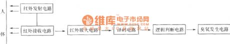
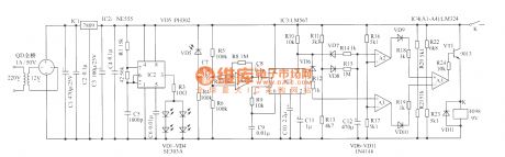
Automatic deodorizer
Published:2011/11/8 21:24:00 Author:Ecco | Keyword: Automatic deodorizer
View full Circuit Diagram | Comments | Reading(1181)
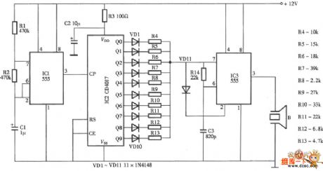
The principle diagram of ultrasonic pest repeller
Published:2011/10/18 3:48:00 Author:Ecco | Keyword: Ultrasonic pest repeller
View full Circuit Diagram | Comments | Reading(5014)
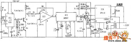
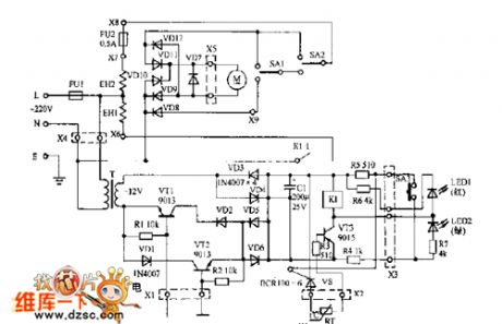
Eggs hatching incubator 4
Published:2011/10/18 3:45:00 Author:Ecco | Keyword: Eggs hatching incubator
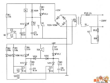
The eggs hatch incubator circuit is composed of the power supply circuit, temperature control circuit and sound and light alarm circuit, and it is shown as the chart. Power supply circuit is composed of the power switch S1, fuse FU2, power transformer T and rectifier diodes VD3 ~ VD6. Temperature control circuit is composed of electric hot thermometer Q1, resistors R1 ~ R3, capacitors C1, C2, thyristor VT1, diode VD9, relay K, light-emitting diode VL1 and manual / automatic switch S2. Sound and light alarm circuit consists of the electric hot thermometer Q2, resistors R4 ~ R9, capacitors C3 ~ C6, thyristors VT2, VT3, diodes VD1, VD2, VD7, VD8, light-emitting diodes VL2, VL3 and buzzer HA.
(View)
View full Circuit Diagram | Comments | Reading(1623)
Icebox operating pilot lamp circuit
Published:2011/10/24 2:36:00 Author:May | Keyword: Icebox, operating pilot lamp
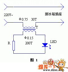
Installing operating light on the mains jack makes it convenient to watch icebox's starting and stoping, and can add the beauty to the mains jack to.
The circuit isshown asdiagram 1.It uses the secondaryinduced current of current transformerto lighten light-emitting diode.The current transformercan look for a slightly larger transistor radioinput or output transformer.And the data can bechanged according to the diagram. people should pay attention to winding-to-winding insulation. Current-limiting resistor R can be chosen in several to tens of ohm. (View)
View full Circuit Diagram | Comments | Reading(994)
Small phone deconcentrator circuit
Published:2011/10/23 22:22:00 Author:May | Keyword: Small phone, deconcentrator
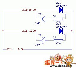
Working principleIfthe line connects totwo phones, which are separately connectedto L and L'. ( We know that when the phone is wating, the different of switch on office line L will have 60V or 48V DC voltage. When it is ringing, there is 95V or 75V AC voltage. When the phone is off-hook, the line voltage will drop to about 10V because the intervene of pnone internal resistance, this device is designed according to this principle. ) If there is phone now, AC current will ring through above-mentioned circuit diagram. If you want to turn to standy phone, the off-hook can dial number keylike standby phone ( attention: thephone must be in impulse dial state).
Components choose
BG1, B2are MCR100-6 small single-track SCRs, andthey require breakdown reverse voltage to begreater than 100V. D1, D2are 18V voltage regulator diodes. The whole cricuit can load in phone junction box.
(View)
View full Circuit Diagram | Comments | Reading(1379)
Home-use fan IR remote control circuit
Published:2011/10/23 21:39:00 Author:May | Keyword: Home-use fan, IR remote control
The diagram is home-use fan IR remote control circuit. This remote controller includes emitter and receiver controlling parts. The nucleus of IR emitter is an astable multivibrator which consists of 555 and R1, w1, c1, andits resonance frequency f=1.44/(R1+2Rw1)C1,whichis adjusted to 38KHz to drive infrared-emitting diode HG310 or HG450 and emit infrared pulse.
Infrared receiving tube should match to transmitting tube, and we should pay attention to light wave and light power. IC1 uses special infrared receiver manifold μPC1373HA to adjustthe L, C4 loop's center frequency in 38KHz, once it receives infrared light pulses, the signal is enlarged,detected,shapedby IC1to make IC1 output low level signal andBG2 stop accordingly, thenits collector outputs high level signal. (View)
View full Circuit Diagram | Comments | Reading(1558)
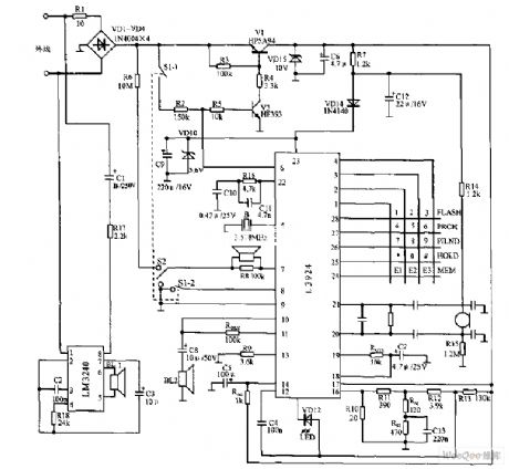
Valuables pilfering tracker circuit diagram 1 (KD400/JD400)
Published:2011/10/19 22:28:00 Author:Rebekka | Keyword: valuables pilfering tracker
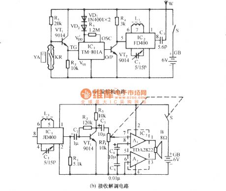
The circuit is shown as figure. It contains wireless Voice FM transmitter and wireless receiver, decoder.The transmitter is placed in the shellof precious appliances. It will automatically launch whistle sound frequency modulation (FM) radio signals. when the appliance is moved, the owner will get the signal by receiver. It will follow the stolen things untill the theft is caught. When someone is moving the valuables, KR and YA will be departed. The touch spot of reed switch will be cut. The TV1 gets bias current and be turned on. Pulse high jump is added to trigger control terminal TG of IC1to trigger itand make a sound. Figure B is receiver demodulation circuit. (View)
View full Circuit Diagram | Comments | Reading(3967)
Hands-free phone chip circuit diagram
Published:2011/10/21 1:56:00 Author:Rebekka | Keyword: Hands-free phone chip
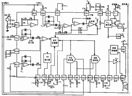
Hands-free phone chip circuit is shown as above, MC3418 chip is widely used in high-quality speakerphone representative blocks and half-duplex voice call. (View)
View full Circuit Diagram | Comments | Reading(2355)
Two-way telephone password device circuit diagram
Published:2011/10/21 2:05:00 Author:Rebekka | Keyword: Two-way telephone password device
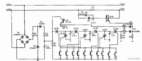
Two-way telephone password device is shown as above, the two-way telephone device is composed of the power circuit, password circuit, * circuit, and self-locking circuit. Password circuit is composed of digital keys 0 to 9, four password set. The figure is set to 4269. The *circuit is composed offour one-way thyristor SCR1 ~ SCR4, three capacitors C2, C3, C4, resistor R4, R5 and diode D3. Self-locking circuit is composed of infrared light emitting diodes D5, D6, infrared receiver, the resistance of transistor BG R7, R8 and diode D4. The 2 ends of LINa, LINb Access an outside line. TELa, TELb pick connect the phone. (View)
View full Circuit Diagram | Comments | Reading(1807)
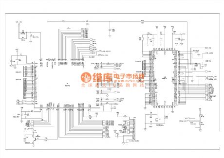
Italy high integrated telephone circuit diagram
Published:2011/9/15 22:48:00 Author:Rebekka | Keyword: Italy, high integrated telephone
Italy high integrated telephone circuit diagram. (View)
View full Circuit Diagram | Comments | Reading(4107)
Fax circuit diagram
Published:2011/9/27 22:56:00 Author:Rebekka | Keyword: Fax circuit
View full Circuit Diagram | Comments | Reading(1196)
SA866 pin array diagram
Published:2011/4/10 22:50:00 Author:may | Keyword: pin array
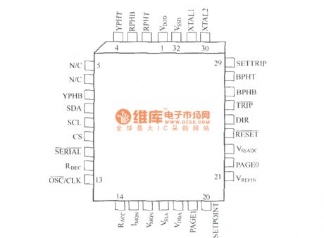
SA866 is special asynchronous machine SPWM control IC. It integrates kinds of protection function except generate SPWM pulse which is meeting requirements according to setup parameter. It also can fast cut off SPWM pulse in emergency, to protect frequency conversion power supply and load.
(View)
View full Circuit Diagram | Comments | Reading(994)
Emergency lighting circuit diagram 03
Published:2011/10/17 2:31:00 Author:Ecco | Keyword: Emergency lighting
View full Circuit Diagram | Comments | Reading(1400)
Electronic sterilizing cabinet circuit diagram 01
Published:2011/10/17 2:24:00 Author:Ecco | Keyword: Electronic sterilizing cabinet
View full Circuit Diagram | Comments | Reading(1069)
Electronic sterilizing cabinet circuit diagram 04
Published:2011/10/17 2:24:00 Author:Ecco | Keyword: Electronic sterilizing cabinet
View full Circuit Diagram | Comments | Reading(957)
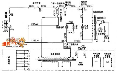
Microwave circuit diagram 02
Published:2011/10/17 2:26:00 Author:Ecco | Keyword: Microwave
View full Circuit Diagram | Comments | Reading(2862)
| Pages:12/126 1234567891011121314151617181920Under 20 |
Circuit Categories
power supply circuit
Amplifier Circuit
Basic Circuit
LED and Light Circuit
Sensor Circuit
Signal Processing
Electrical Equipment Circuit
Control Circuit
Remote Control Circuit
A/D-D/A Converter Circuit
Audio Circuit
Measuring and Test Circuit
Communication Circuit
Computer-Related Circuit
555 Circuit
Automotive Circuit
Repairing Circuit