
Electrical Equipment Circuit
Index 16
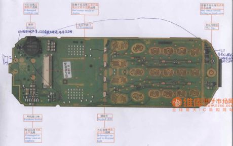
Siemens 3508 mobile phone maintenance circuit diagram
Published:2011/8/17 21:55:00 Author:Jessie | Keyword: mobile phone maintenance
View full Circuit Diagram | Comments | Reading(1229)
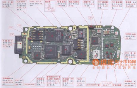
Waveguide MC938/936 mobile phone maintenance circuit diagram
Published:2011/8/17 21:56:00 Author:Jessie | Keyword: mobile phone maintenance
View full Circuit Diagram | Comments | Reading(2106)
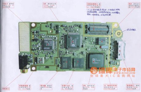
DongXin 788 mobile phone maintenance circuit diagram
Published:2011/8/17 21:47:00 Author:Jessie | Keyword: mobile phone maintenance
View full Circuit Diagram | Comments | Reading(2463)
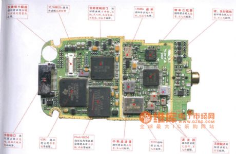
Soutec 70 mobile phone maintenance circuit diagram
Published:2011/8/17 21:46:00 Author:Jessie | Keyword: mobile phone maintenance
View full Circuit Diagram | Comments | Reading(2237)
Automatic washing circuit
Published:2011/8/17 20:46:00 Author:Jessie | Keyword: Automatic washing
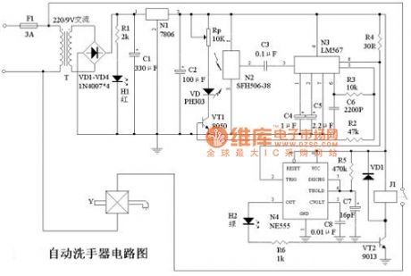
The principle of automatic washing circuit is shown in figure 1, and220VAC circuitis bucked by transformer T, and it changes to low voltage current. Then it is regulated by three terminal voltage circuit 7806 toget 6VDC to supply to control circuit. H1is a red led, which is used as a power supply instruction. N2 is theinfrared receiving circuit SFH506-38, and N3is PLL audio decoder LM567, and N3 and R3, C6form an oscillator, and R3, R6 decide the center frequency of N3's internal vco. LM567's pin 3 is the signal input,pin 8 islogic output, its output terminal is OC door output, max irrigation current is 100mA, the working voltage of LM567is 4.75 V ~ 9V. Working frequency can be from a few Hz to 500 KHZ, andthestatic working current is8mA. N4 isNE555 timer, andits peripheral componentsform the single state timing circuit, the purpose is to guarantee the normal water for washing hands when hands occasionally deviate infrared's detection range. (View)
View full Circuit Diagram | Comments | Reading(1310)
The white light LED drive circuit
Published:2011/8/23 22:06:00 Author:Borg | Keyword: white light, LED drive
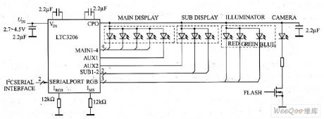
Compared to the EL backlight illuminating apparatus, the white light LED has a longer lifespan and its power consumption is lower. Most of the manufacturers confess that it has a working lifespan of 1 million hours under the standard condition, its efficiency of converting electricity into light is 80%. Since 1993 when the blue light LED whose wavelength is 470nm, the LEDs whose output is from ultraviolet light to yellow light are widely used. The wavelength of the white light LED is 430~700mm.
(View)
View full Circuit Diagram | Comments | Reading(976)
The booster and electric charge pump converter drive LED application circuit
Published:2011/8/23 22:07:00 Author:Borg | Keyword: booster, electric charge, pump converter
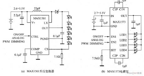
In the figure, there are two projects, MAX1561 booster converter and MAX1573 pump, to drive the LED, and the complexes of the two circuits are almost the same, i.e both of the two circuits have several simple elements, but the booster converter needs inductors and Schottky diodes(some booster converters integrate the Schottky diode inside themselves, but the efficiency is often low), and the electric charge pump circuit doesn't need the inductor.
(View)
View full Circuit Diagram | Comments | Reading(1563)
The domestic experiment electro medical apparatus circuit
Published:2011/8/23 22:13:00 Author:Borg | Keyword: domestic, electro medical apparatus
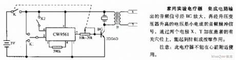
The domestic experiment electro medical apparatus circuit The audio signal output by the integrated circuit is amplified by BG, and the voltage boosted by the transformer is the audio pulse signal of the small current, by putting the two electrodes of X and Y on the acupuncture points of the patients, the machine can fulfill the function of puncturing or massage.Notes: the electro medical apparatus can't be used near the heart.
(View)
View full Circuit Diagram | Comments | Reading(1474)
The electric mosquito dispeller
Published:2011/8/23 22:36:00 Author:qqtang | Keyword: mosquito dispeller
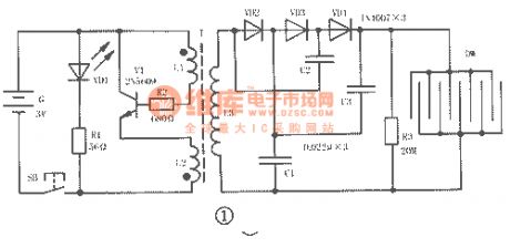
The electric mosquito dispeller circuit is shown in figure 1, which consists of the high frequency oscillator circuit, triple voltage rectifier circuit and high voltage shock net DW.
When the power supply switch SB is pressed, the high frequency oscillator, which consists of the triode VT and transformer T, is getting power and working, it switches the 3V DC into the 18kHz high frequency AC, then it is boosted to about 500V(which is got from the 2 terminals of L3) by T, and then it is boosted to 1500V by the diodes VD2~VD4 and capacitors C1~C3, the boosted voltage is added on the metal net DW. (View)
View full Circuit Diagram | Comments | Reading(4051)
Optical electronic doorbell 2
Published:2011/8/11 21:05:00 Author:Ecco | Keyword: Optical electronic doorbell
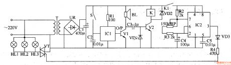
The optical electronic doorbell circuit is composed of the power supply circuit, oscillator circuit, music generating circuit and color bulb control circuit and other components, and it is shown in Figure 3-112. Power supply circuit consists of the power transformer T, bridge rectifier UR and filter capacitor CI. Oscillator circuit consists of the time-base integrated circuit IC2 and external RC components. Music generating circuit consists of the button S, music integrated circuit ICl, transistor Vl, speaker BL and resistor Rl, capacitor C2 and so on. Color bulb control circuit consists of lantern lights HL1-HL3, two-way thyristor VT, transistor V2 and relay K and other components. Rl-R4 select the 1/4W or 1/8W carbon film resistors.
(View)
View full Circuit Diagram | Comments | Reading(1224)
Infrared reflective electronic doorbell circuit diagram
Published:2011/8/22 3:20:00 Author:Ecco | Keyword: Infrared reflective , electronic doorbell
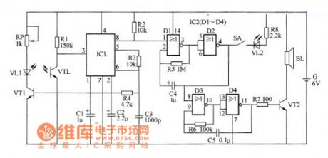
Infrared reflective electronic doorbell circuit is composed of the infrared transmitter, infrared receiver circuit, low-frequency oscillator, audio oscillator and audio output circuit, and it is shown in Figure 1. IC1 uses LM567 integrated circuit; IC2 uses CD4.001 or TC4001 4-2 input NOR gate integrated circuit. VTl and VT2 select the silicon NPN transistors. VLl and VTL select the matching infrared emitting diode and phototransistor red external board. VL2 uses the Φ5mm red high-brightness light-emitting diode. R1-R8 select the 1/4W carbon film resistors. RP chooses the membrane variable potentiometer.
(View)
View full Circuit Diagram | Comments | Reading(2583)
Electronic password switch 1
Published:2011/8/8 22:08:00 Author:Ecco | Keyword: Electronic password switch
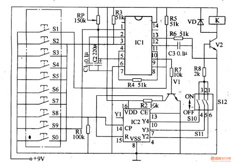
The electronic password switch circuit is composed of the password input circuit, monostable flip-flop, bistable flip-flop, reset circuit, control executive circuit and count divider, and it is shown in Figure 3-96. Password input circuit is composed of buttons S0-S9. Monostable integrated circuit is composed of the internal time-base circuit of the dual time-base IC IC1 and external components of pin2-6. The bistable flip-flop is composed of IC1's another time-base IC and external components of pin8-13. Count divider circuit is composed of the counter / divider integrated circuit IC2 and resistor Rl and so on. Reset circuit consists of resistors R2, R7, and transistor Vl. Control implementation circuit is composed of setting switches S10-S12 and resistor R8, transistor VZ, relay (or electronic lock) K, diode VD.
(View)
View full Circuit Diagram | Comments | Reading(2479)
Electronic password switch 2
Published:2011/8/8 22:11:00 Author:Ecco | Keyword: Electronic password switch
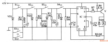
The electronic password switch circuit is composed of the password control circuit and control implementation circuit, and it is shown in Figure 3-97. Password control circuit consists of password control buttons Sl-Sl2, diodes VDl-VD4, resistors Rl-R5, capacitors C1-C5 and four NAND gate IC lC . Control implementation circuit consists of the relay K, diode VD5, transistor V, and resistors R6, R7. Rl-R7 use the 1/4W carbon film resistors or metal film resistors. Cl-C5 select the aluminum electrolytic capacitors with voltage in 16V . VDl-VD4 use 1N4148 silicon switch diodes; VD5 uses the 1N4 1907 silicon rectifier diode.
(View)
View full Circuit Diagram | Comments | Reading(1377)
Two-tone electronic doorbell 1
Published:2011/8/11 1:51:00 Author:Ecco | Keyword: Two-tone electronic doorbell
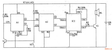
The two-tone electronic doorbell circuit is composed of the input trigger circuit and audio output circuit, ans it is shown in Figure 3-107. The input trigger circuit is composed of the doorbell button S, transistor V1, resistors Rl-R3, capacitor Cl and dual D flip-flop integrated circuit ICl (Al, A2). Audio output circuit consists of the audio output circuit integrated circuit IC2, capacitor C2, resistors R4, R5, transistor V2 and speaker BL. Rl-R5 select the l/8W or 1/4W carbon film resistors. Cl and C2 select the aluminum electrolytic capacitors with voltage in lOV. Vl uses the S9014 or 3DGl2 silicon NPN transistor; V2 uses Sg013 or S8050 silicon NPN transistor.
(View)
View full Circuit Diagram | Comments | Reading(2626)
Two-tone electronic doorbell 2
Published:2011/8/9 22:32:00 Author:Ecco | Keyword: Two-tone electronic doorbell
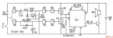
The two-tone electronic doorbell circuit is composed of the trigger control circuit and doorbell generating circuit, and it is shown in Figure 3-108. Trigger control circuit consists of doorbell button S, resistors Rl-R3, electrical wear devices Cl-C3, diodes VDl-VD3, six NOT gate integrated circuit ICl (Dl-D6) and the electronic switch IC lC3 (S1, S2). Doorbell generating circuit consists of the resistors R4-R6, audio IC lC2, capacitor C4, transistor V, and speaker BL. Rl-R6 select the 1/4W metal film resistors or carbon film resistors. Cl-C4 select the aluminum electrolytic capacitors with voltage value being greater than 6V. VDl-VD3 use the 1N4148 silicon switch diodes.
(View)
View full Circuit Diagram | Comments | Reading(2439)
Three-tone electronic doorbell 1
Published:2011/8/15 21:19:00 Author:Ecco | Keyword: Three-tone electronic doorbell
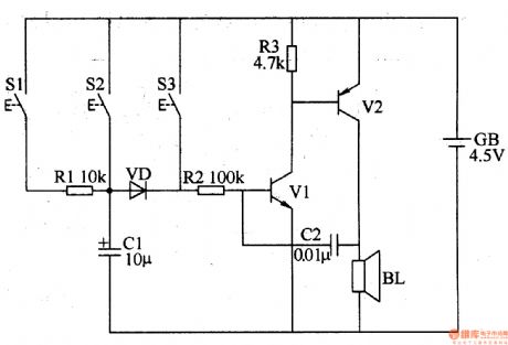
The three-tone electronic doorbell circuit consists of buttons Sl-S3, transistors Vl, V2, speaker BL, resistors Rl-R3, capacitors Cl, C2, diode VD and battery GB, and it is shown in Figure 3-109. Rl-R3 use the 1/4W carbon film resistors or metal film resistors. Cl uses the electrolytic capacitor with voltage in 16V; C2 uses the monolithic capacitors or polyester capacitors. VD uses the 2AP9 germanium ordinary diode or 1N4148 silicon switching diode. Vl uses the 3DG6 or S9013 silicon NPN transistor; V2 uses the 3AX31 germanium PNP transistor.
(View)
View full Circuit Diagram | Comments | Reading(3874)
Three-tone electronic doorbell 2
Published:2011/8/15 21:22:00 Author:Ecco | Keyword: Three-tone electronic doorbell
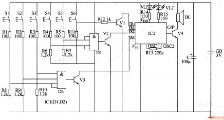
The three-tone electronic doorbell circuit consists of the coding triggered circuit, multi-tone generator and audio amplifier circuit, and it is shown in Figure 3-110. Coding trigger circuit is composed of the buttons Sl-S6, two four-input AND gate (DI, D2) integrated circuit ICI, resistors Rl-Rll and transistors Vl-V3 and so on. Multi-tone sound generator circuit consists of the train sound analog integrated circuit IC2, LEDs VLl and VL2 and resistors R13-Rl5. Audio amplifier circuit consists of audio amplifier tube V4 and speaker BL. Rl-Rl5 use the 1/4W or 1/8W carbon film resistors.
(View)
View full Circuit Diagram | Comments | Reading(4205)
Optical electronic doorbell 1
Published:2011/8/11 20:59:00 Author:Ecco | Keyword: Optical electronic doorbell
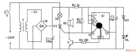
The optical electronic doorbell circuit is composed of the power supply circuit and light and sound circuit, and it is shown in Figure 3-111. Power supply circuit consists of the doorbell button S, power transformer T, bridge rectifier UR and filter capacitor Cl. Sound and light circuit consists of colored bulb HL, thyristor VT, music integrated circuit IC, resistors Rl-R3, capacitor C2, diode VD, thyristor VT, LED VL and speaker BL. Rl-R3 use 1/4W metal film resistors or carbon film resistors. C2 and C2 select the aluminum electrolytic capacitors with voltage in lOV. VD uses the 1N4148 silicon switch diode.
(View)
View full Circuit Diagram | Comments | Reading(2000)
Industrial electronic ignition circuit diagram
Published:2011/8/22 2:27:00 Author:Ecco | Keyword: Industrial electronic ignition
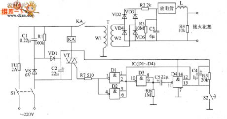
The industrial electronic ignition circuit is composed of the power supply circuit, ignition starter control circuit and boost ignition circuit, and it is shown as the chart. Power supply circuit is composed of the power switch S1, fuse FU, buck capacitor C1, discharge resistor R1, rectifier diode CVD1, voltage regulator diode VS and filter capacitor C2. Start ignition control circuit is composed of the ignition button S2, resistors R5 ~ R7, intergranular tube VT, relay KA and capacitors L4, C5. Boost ignition circuit consists of step-up transformer T, rectifier diodes VD2 ~ VD5, capacitor C3, resistors R2 ~ R4, discharge tube, inductor L and spark plug.
(View)
View full Circuit Diagram | Comments | Reading(2575)
Infrared reflectance electronic doorbell
Published:2011/8/9 21:38:00 Author:Ecco | Keyword: Infrared reflectance, electronic doorbell
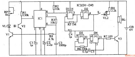
The infrared reflectance electronic doorbell consists of infrared transmitter circuit, infrared receiver circuit, low-frequency oscillator, audio oscillator and audio output circuit, and it is shown in Figure 3-121. Infrared transmitter circuit consists of the infrared transmitter tube (infrared light-emitting diode) VLl, driver transistor Vl, the pin 6 internal cirucuit of integrated circuit ICl and the external components. Infrared receiver circuit consists of infrared / receiver tube (infrared phototransistor) V2 and pin 3 internal circuit of IC1. Low-frequency oscillator consists of the NOR gates Dl and D2 of four NOR gate digital IC ICZ (CD4001) and the resistor R5, capacitor C4 and so on.
(View)
View full Circuit Diagram | Comments | Reading(2098)
| Pages:16/126 1234567891011121314151617181920Under 20 |
Circuit Categories
power supply circuit
Amplifier Circuit
Basic Circuit
LED and Light Circuit
Sensor Circuit
Signal Processing
Electrical Equipment Circuit
Control Circuit
Remote Control Circuit
A/D-D/A Converter Circuit
Audio Circuit
Measuring and Test Circuit
Communication Circuit
Computer-Related Circuit
555 Circuit
Automotive Circuit
Repairing Circuit