
Electrical Equipment Circuit
Index 9
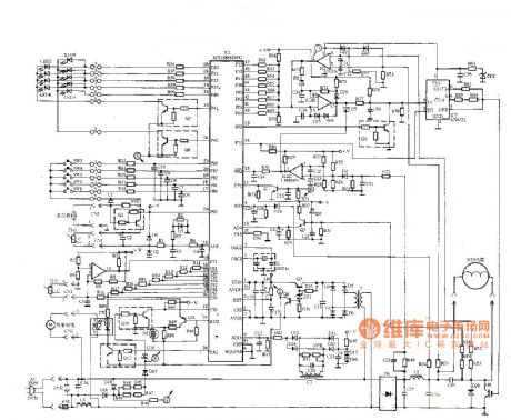
Panasonic KY-P2N microwave cooker principle diagram
Published:2011/8/29 22:50:00 Author:Jessie | Keyword: Panasonic , microwave cooker
View full Circuit Diagram | Comments | Reading(2782)
Glanze WD-900B microwave oven principle circuit
Published:2011/8/30 1:44:00 Author:Jessie | Keyword: microwave oven, Glanze
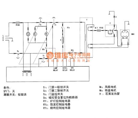
R1-The first door interlock switch; S2-the second door interlock switch; S3-door monitoring switch, S4-magnetron self-resetting thermal breaker, RY1-oven light control relay, RY2-microwave control relay, RY3 - BBQ control relay, M1-fan motor, M2-wheel motor, H-quartz heating tube. (View)
View full Circuit Diagram | Comments | Reading(2598)
Low-power consumption AC flashing light circuit diagram
Published:2011/10/26 21:49:00 Author:May | Keyword: Low-power consumption , AC flashing light
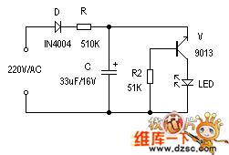
It uses the charging and discharging characteristic of capacitor C and the negative resistance characteristic of triode V under the breakdown condition to constitute a squegger oscillator. After getting power, 220V alternating current is half-wave rectified by diode D, current limited by resistor R to charge for C. When C's both sides voltage rises to V's breakdown voltage ( the actual value is approximately 9V), then it rapidly discharges by V to make the LED connected in discharging loop illuminate. After the discharging ended, V regains the closure condition, C starts to charge and to be redundant the above process. V has the synchronized signal which added to base to trigger the avalanche. Electric circuit working actual value is only 0.17mA. (View)
View full Circuit Diagram | Comments | Reading(1829)
Simple and practical human approach detector circuit diagram
Published:2011/5/16 23:37:00 Author:May | Keyword: human approach detector
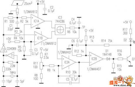
Human approach detector circuit is composed of integrated operational amplifier, gate circuit and resistor-capacitor unit in the diagram. Among them, 1MHz oscillator consists of reverser T1, 1MHz crystal oscillator and resistor-capacitor unit. The oscillator signal is shaped by T2 and then T2 outputs square signal. It adopts a piece of 25cm2 copper clad plates to make up inductor. Human body is equal to another polar plate when human nears the copper clad plate. It can generate capacitance enlarge along with human’s approach and the capacity is 2~6pF. This incremental capacitance can make the after IC3 output pulse signal which pulse duty factor is proportional to incremental capacitance. One way of T2 outputted square wave is sent to comparer IC1B by R3, and is add to one input end of XOR gate IC3 after enlarged; another way is first delayed by R1 and C1, than enlarged by comparer IC1A and added to another input end of XOR gate IC3, thereby the duty factor of XOR gate IC3 outputted square signal is in direct proportion to the delay of R1 in the input circuit, then it generates DC current which is in direct proportion to the distance of human approach after filtered by R6 and C4. (View)
View full Circuit Diagram | Comments | Reading(2977)
Children anti-lost reminder circuit
Published:2011/10/24 1:35:00 Author:May | Keyword: Children anti-lost reminder
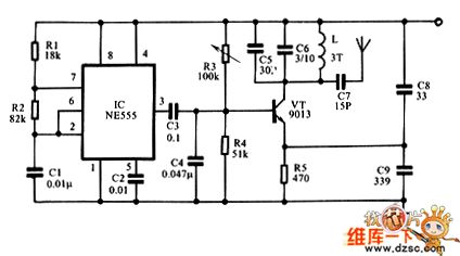
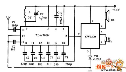
Figure 1 shows the transmitter circuit. It consists of time-base IC NE555, R1, R2, C1. 1KHz low-frequency oscillator can modulate the high-frequency oscillator composed of transistor VT and peripheral components, then the modulated high-frequency signal is sent out by the inside tiny antenna from the C7. C8 is used to add broadband and prevent impact on the frequency from human induction. Actual use proves that it is the essential element. Figure 2 shows the receiver circuit. When the receiver receives the signal sent by the transmitter, the pin ② of IC TDA7000 outputs low level, the music IC CW9300 has no high level to trigger signal and does not work, then speaker BL is silent.
(View)
View full Circuit Diagram | Comments | Reading(2887)
TV lightning protection circuit
Published:2011/10/26 22:14:00 Author:May | Keyword: TV lightning protection
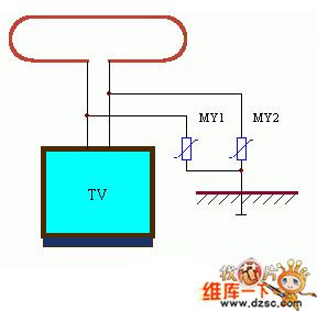
The application circuit of this set is shown in the picture. Watching TV on in thunderstorms, the thunderbolt can scurry into TV and damage it through two ways; one is through outdoor television antenna; the other is through TV power line. The former often damages radio-frequency head, the latter often damages TV power supply circuit and line-field output circuit. Adding voltage dependent resistor on outdoor antenna can avoidthe consequence, and itrequires voltage dependent resistor MY to beconnected with ground directly. Protective power supply part application circuit's connectioncan be seen in the picture. They general protect induced lightning, if it meets the direct lightening, because of thedirect lightening's huge current and extreme high voltage, voltage dependent resistor cannot do anything about it, so we should place lightning conductor around outdoor antenna, the position of outdoor antenna should bein the protected areas.
(View)
View full Circuit Diagram | Comments | Reading(2106)
Keyer dimmer table lamp circuit
Published:2011/10/26 20:58:00 Author:May | Keyword: Keyer, dimmer table lamp
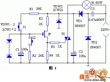
Keyer dimmer table lamp adopts two touch buttons to adjust the light. The light changes weaken from strong when peopletouch one of the buttons, and it changes strong from weaken when peopletouch the other button.
Working principle
The principle of this circuit is shown in diagram 1. Capacitance buckDC power supply is composed of VD1, VD2, C2 and C3. Triac VS's trigger circuit is composed of MOSFET, C1 and so on. DW is protecting diode. It can prevent the grid breakdownfrom FET. When people press down S1, R1 charges to the C1 to increase the grid bias, then the silicon-controlled rectifier's trigger current rises, the breakover angle increases, the optical fiber increases; when people press down S2, C1 discharges along the R2, the grid bias drops, silicon-controlled rectifier's breakover angle lessens, the optical fiber changes darker. (View)
View full Circuit Diagram | Comments | Reading(3183)
Banqiu CCDT5-4 electronic thermostat electric-fry pan circuit diagram
Published:2011/8/29 20:53:00 Author:Jessie | Keyword: Banqiu , electronic thermostat , electric-fry pan
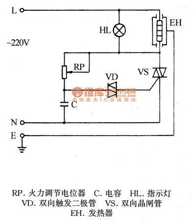
RP-fire adjustment potentiometer, C-capacitor, HL-light, VD-way trigger diode, VS-Triac, EH-heater.
(View)
View full Circuit Diagram | Comments | Reading(2186)
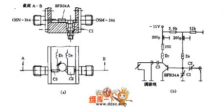
Small FM transmitter (wireless speaker ) circuit diagram
Published:2011/12/9 1:30:00 Author:Ecco | Keyword: Small , FM transmitter, wireless speaker
View full Circuit Diagram | Comments | Reading(1870)
RSCW-102 rechargeable shaver circuit
Published:2011/12/7 1:57:00 Author:Ecco | Keyword: rechargeable shaver
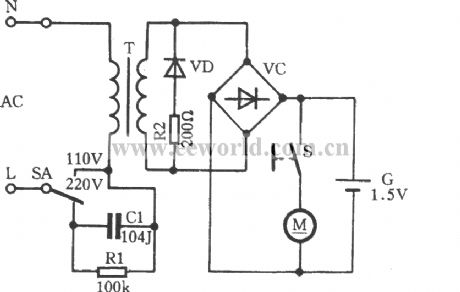
RSCW-102razor is suitable for AC , DC , and it has a charging function , and it isshown inthe circuit .
(View)
View full Circuit Diagram | Comments | Reading(2247)
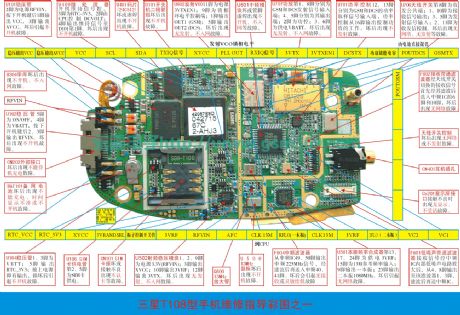
Samsung T100/T108 mobile phone repairing physical diagram (2)
Published:2011/11/29 1:40:00 Author:Ecco | Keyword: Samsung , mobile phone repairing , physical diagram
View full Circuit Diagram | Comments | Reading(7405)
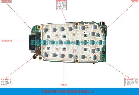
Samsung S300/S308 mobile phone repairing physical diagram(2)
Published:2011/11/29 1:48:00 Author:Ecco | Keyword: Samsung , mobile phone repairing , physical diagram
View full Circuit Diagram | Comments | Reading(1154)
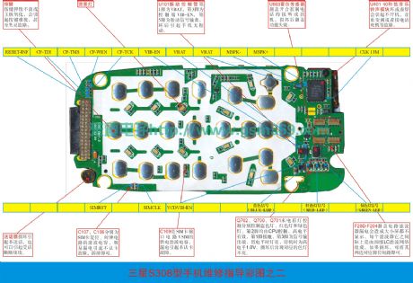
Samsung S300/S308 mobile phone repairing physical diagram(1)
Published:2011/11/29 1:49:00 Author:Ecco | Keyword: Samsung , mobile phone repairing , physical diagram
View full Circuit Diagram | Comments | Reading(2357)
Samsung s500/s508 mobile phone repairing physical diagram (2)
Published:2011/11/29 1:43:00 Author:Ecco | Keyword: Samsung , mobile phone repairing, physical diagram

View full Circuit Diagram | Comments | Reading(1313)
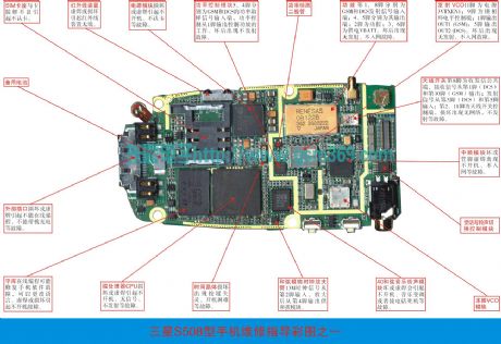
Samsung s500/s508 mobile phone repairing physical diagram (1)
Published:2011/11/29 1:42:00 Author:Ecco | Keyword: Samsung, mobile phone repairing , physical diagram
View full Circuit Diagram | Comments | Reading(4668)
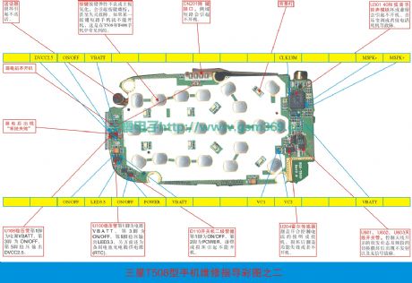
Samsung T500/T508 mobile phone repairing physical diagram (2)
Published:2011/11/29 1:42:00 Author:Ecco | Keyword: Samsung, mobile phone repairing , physical diagram
View full Circuit Diagram | Comments | Reading(1728)
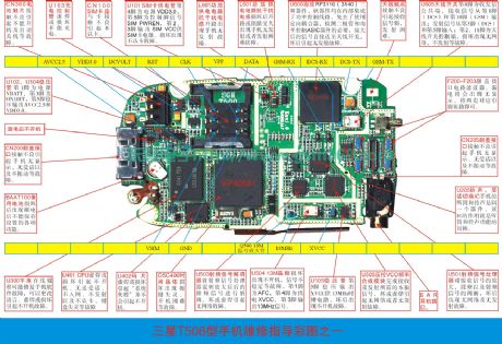
Samsung T500/T508 mobile phone repairing physical diagram (1)
Published:2011/11/29 1:40:00 Author:Ecco | Keyword: Samsung , mobile phone repairing , physical diagram
View full Circuit Diagram | Comments | Reading(4921)
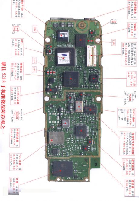
Konka 5218 repairing diagram 1
Published:2011/11/29 1:47:00 Author:Ecco | Keyword: Konka , repairing diagram
View full Circuit Diagram | Comments | Reading(1026)
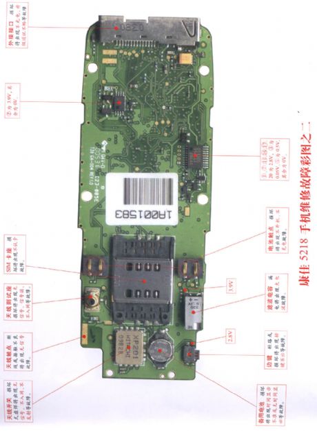
Konka 5218 repairing diagram 2
Published:2011/11/29 1:46:00 Author:Ecco | Keyword: Konka , repairing diagram
View full Circuit Diagram | Comments | Reading(956)
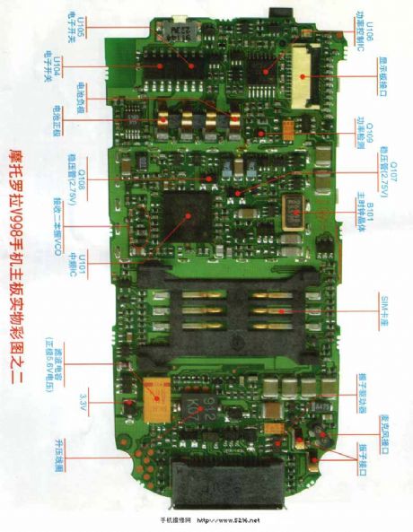
Motorola V998 repairing circuit diagram 2
Published:2011/11/29 1:45:00 Author:Ecco | Keyword: Motorola, repairing
View full Circuit Diagram | Comments | Reading(896)
| Pages:9/126 1234567891011121314151617181920Under 20 |
Circuit Categories
power supply circuit
Amplifier Circuit
Basic Circuit
LED and Light Circuit
Sensor Circuit
Signal Processing
Electrical Equipment Circuit
Control Circuit
Remote Control Circuit
A/D-D/A Converter Circuit
Audio Circuit
Measuring and Test Circuit
Communication Circuit
Computer-Related Circuit
555 Circuit
Automotive Circuit
Repairing Circuit