
Electrical Equipment Circuit
Index 20
Frost alarm circuit diagram 1
Published:2011/8/11 1:18:00 Author:Ecco | Keyword: Frost alarm
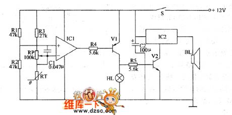
The frost alarm circuit is composed of the frost detection circuit and the sound and light alarm circuit, and it is shown in Figure 1. Frost detection circuit consists of the thermistor RT, resistors RI ~ R3, potentiometer RP, capacitor C1 and operational amplifier integrated circuit ICl. Sound and light alarm circuit consists of resistors R4, R5, transistors VI, Y2, alarm indicator HL, audio integrated circuit IC2 and speaker BL. R1 ~ R5 select the l/4W carbon film resistors or metal film resistors. RP uses the synthetic membranes variable resistor.
(View)
View full Circuit Diagram | Comments | Reading(1468)
Production volume automatic counter circuit diagram 2
Published:2011/8/15 2:08:00 Author:Ecco | Keyword: Production volume, automatic counter
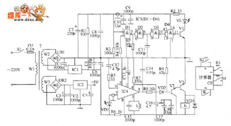
The production volume automatic counter circuit is composed of the power supply circuit, infrared transmitter circuit, infrared receiver amplifier circuit, control implementation circuit and counter control circuit, and it is shown as teh chart. Power supply circuit is composed of the power switch S1, fuse FU, power transformer T, bridge rectifiers UR1 and UR2, three-terminal voltage regulator integrated circuits IC1 and IC2, capacitors C1 ~ C8 and resistor R1. Infrared transmitter circuit consists of NAND gate integrated circuit IC3 (D1 ~ D4), transistor V1, infrared light-emitting diode VL, resistors R2 ~ M, capacitors C9 ~ C11 and potentiometer RP.
(View)
View full Circuit Diagram | Comments | Reading(1595)
Industrial degaussing device circuit diagram
Published:2011/8/10 21:21:00 Author:Ecco | Keyword: Industrial degaussing device
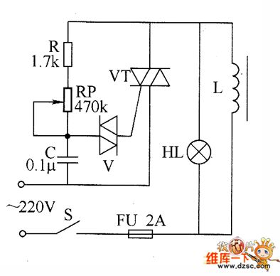
The industrial degaussing device circuit is composed of the fuse FU, thyristor VT, two-way trigger diode V, degaussing coil L, resistor R, potentiometer RP, capacitor C, LED HL, fuse FU and power switch s, and it is shown as the chart. R selects the 1/2W metal film resistor. RP chooses the potentiometer or solid synthetic organic carbon potentiometer with voltage being more than 2W. C uses the CBB capacitor polyester capacitor with the voltage in 250V. V uses the DB3 or 2CTS two-way trigger diode. VT uses the 100V, 10A two-way intergranular tube. HL chooses the 15W, 220V incandescent bulb. S selects the 5A, 220V power switch.
(View)
View full Circuit Diagram | Comments | Reading(3220)
Production volume automatic counter circuit diagram 1
Published:2011/8/15 2:05:00 Author:Ecco | Keyword: Production volume , automatic counter
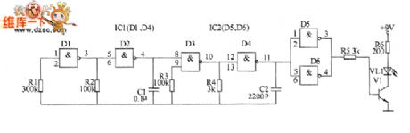
Infrared transmitter circuit is composed of the capacitance feedback oscillator circuit, 40kHz pulse oscillator and driver circuit, and it is shown as the chart. Capacitance feedback oscillator circuit consists of D1 and D2 which are inside of NAND gate integrated circuit IC1 (D1 ~ D4) and the internal resistors R1 and R2, capacitor C1. 40kHz pulse oscillator circuit consists of IC1's internal D3 and D4 and resistors R3 and R4, capacitor C2. Driver circuit consists of NAND gate integrated circuit IC2 (D5, D6), resistors R5 and R6, transistor V1 and infrared light-emitting diode VL1.
(View)
View full Circuit Diagram | Comments | Reading(1106)
Cumulative timer circuit diagram
Published:2011/8/10 22:13:00 Author:Ecco | Keyword: Cumulative timer
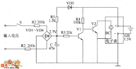
The cumulative timer circuit consists of resistor R1 and spreadsheet internal crystal oscillator BC, and it is shown as the chart. R1 and R2 choose the metal film resistors: R3 ~ R5 select the 1/8W metal film resistors. C select the aluminum electrolytic capacitor with voltage being above 10V. VD1 ~ VD4 use the 1N4007 silicon rectifier diodes; VD5 uses the 1N4l48 or 2CK44A silicon switching diode. V1 and V2 use S9013 or 3DG6 silicon NPN transistors. Digital watchesse use the multi-function LCD digital watches.
(View)
View full Circuit Diagram | Comments | Reading(1818)
Liquid level controller circuit diagram 1
Published:2011/8/15 22:10:00 Author:Ecco | Keyword: Liquid level controller
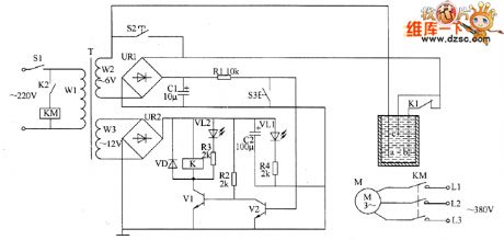
The liquid level controller circuit consists of the power supply circuit and level detection control circuit, and it is shown as the chart. Power supply circuit consists of the power switch S1, power transformer T, bridge rectifiers UR1, UR2 and filter capacitors C1, C2. Liquid level detection control circuit is composed of the test electrodes a ~ c, control buttons S2, S3, resistors R1 ~ M, transistors V1, V2, LEDs VL1, VL2, relay K, and AC contactor KM, diode VD. R1 ~ R4 select the 1/4W metal film resistors or carbon film resistors.
(View)
View full Circuit Diagram | Comments | Reading(2738)
Animal litter teller device 2
Published:2011/8/10 3:36:00 Author:Ecco | Keyword: Animal litter teller
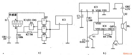
The animal litter teller circuit is composed of the detection signal wireless transmitter circuit, wireless receiver alarm circuit, and it is shown in Figure 4-17. Detection signal wireless transmitter circuit is composed of the battery GBl, power switch Sl, sensors, resistors Rl, R2, NOT gate integrated circuit ICl (Dl-D4) and wireless remote control transmitter integrated circuit IC2. Wireless receiver alarm circuit is composed of the wireless remote control integrated circuit IC3, resistors R3, R4, capacitors Cl, C2, transistors Vl, V2, alarm sound integrated circuit IC4, battery GB2, power switch S2 and the speaker BL.
(View)
View full Circuit Diagram | Comments | Reading(969)
Animal litter teller device 1
Published:2011/8/10 3:32:00 Author:Ecco | Keyword: Animal litter teller
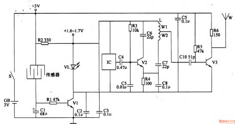
The animal litter teller circuit is composed of the detection control circuit and alarm signal transmission circuit, and it is shown in Figure 4-16. Detection control circuit consists of comb detection sensor, resistors Rl, R2, capacitors Cl-C3, light-emitting diode V1 and transistor VL. Alarm signal transmission circuit consists of the audio integrated circuit IC, capacitors C4-ClO, resistors R3-R6, transistors V2, V3, antenna W and inductor L. RI-R6 select the 1/4W metal film resistors or carbon film resistors. C2, C5, C8 and C9 use the monolithic capacitors.
(View)
View full Circuit Diagram | Comments | Reading(1083)
Chicks hatched informing device 3
Published:2011/8/11 20:45:00 Author:Ecco | Keyword: Chicks , hatched informing device
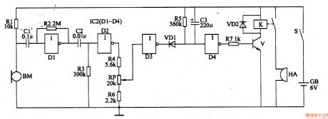
The chicks hatched informing device circuit is composed of the sonic circuit, delay circuit and alarm circuit and other components, and it is shown in Figure 4-15. Sonic circuit consists of the microphone BM, NOT gate circuits D1, D2 which are inside of NOT gate IC (Dl-D4), resistors Rl-R4, R6, potentiometer RP and capacitors Cl, C2 and so on. Delay circuit consists of resistor R5, capacitor C3, diode VDl and NOT gate circuits D3, D4 which are inside of NOT gate IC. Alarm circuit consists of the relay K, diode VD2, transistor V, resistor R7 and buzzer HA. Rl-R7 select the 1/4W metal film resistors or carbon film resistors. RP uses the small synthetic membrane potentiometer or variable resistor.
(View)
View full Circuit Diagram | Comments | Reading(971)
Chicks hatched informing device 2
Published:2011/8/11 20:36:00 Author:Ecco | Keyword: Chicks , hatched informing device
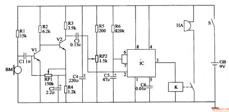
The chicks hatched informing device circuit is composed of the sonic amplifier circuit, monostable delay circuit and alarm circuit, and it is shown in Figure 4-14. Sonic amplifier circuit consists of the microphone amplifier BM, resistors Rl-R4, capacitors Cl, C2, potentiometer RPl and transistors Vl, V2. Monostable delay circuit consists of the time-base lC, resistors R5, R6, potentiometer RP2 and capacitors C3-C5. Alarm circuit consists of the relay K and buzzer HA. Rl-R6 select the 1/4W metal film resistors or carbon film resistors. RPl and RP2 use the small solid potentiometer or WSW solid variable resistor.
(View)
View full Circuit Diagram | Comments | Reading(974)
Chicks hatched informing device 1
Published:2011/8/11 20:32:00 Author:Ecco | Keyword: Chicks , hatched informing device
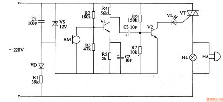
The chicks hatched informing device circuit is composed of the power supply circuit, audio amplifier and sound and light alarm circuit, and it is shown in Figure 4-13. Power supply circuit consists of the current limiting resistor Rl, rectifier diode VD, voltage regulator diode VS and filter capacitor CI. Audio amplifier circuit consists of the microphone BM, transistors Vl, V2, resistors Rl-R7 and capacitors C2, C3. Sound and light alarm circuit consists of the thyristor VT, LED VL, bell HA and lights HL. Rl uses the 3W metal film resistor; R2-R7 select the 1/4W carbon film resistors. VD uses the 1N4007 silicon rectifier diode.
(View)
View full Circuit Diagram | Comments | Reading(923)
Chicken male and female discriminator 2
Published:2011/8/11 20:23:00 Author:Ecco | Keyword: Chicken discriminator, male and female
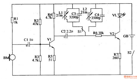
The chicken male and female discriminator circuit is composed of the pickup amplifier circuit, frequency selection circuit and LED driver circuit, and it is shown in Figure 4-12. Pickup amplifier circuit consists of the microphone BM, transistor Vl, resistors Rl-R5 and capacitor Cl. Frequency selection circuit consists of the inductors Ll, K2, capacitors C3, C4 and switch Sl. Ll and C3 form the 5.2kHz frequency selection loop, then L2 and C4 form the 4.8kHz frequency selection loop. LED driver circuit is composed of the capacitor C2, resistors R6, R7, transistor V2 and light emitting diode VL. Rl-R7 select the 1/8W metal film resistors or carbon film resistors.
(View)
View full Circuit Diagram | Comments | Reading(1587)
Chicken male and female discriminator 1
Published:2011/8/11 22:12:00 Author:Ecco | Keyword: Chicken discriminator, male and female discriminator
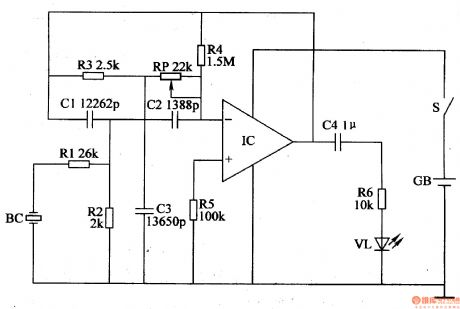
The chicken male and female discriminator circuit is composed of the audio detection circuit, active band-pass filter and LED display circuit, and it is shown in Figure 4-11. Audio detection circuit consists of piezoelectric ceramic BC and resistor Rl, R2. Active band-pass filter is composed of the operation integrated circuit IC and resistors R3-R5, capacitors Cl-C3, potentiometer RP. LED display circuit is composed of the capacitor C4, resistor R6 and light-emitting diode VL. Rl-R6 select the 1/8W precision metal film resistors(error is ± 1%). RP uses the small synthetic film variable resistor. Cl-C3 chooses the high-frequency ceramic capacitors, C4 uses the monolithic capacitor.
(View)
View full Circuit Diagram | Comments | Reading(2188)
Eggs automatic incubator 3
Published:2011/8/10 2:48:00 Author:Ecco | Keyword: Eggs automatic incubator
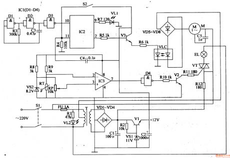
The eggs automatic incubator circuitis composed ofthe power supplycircuit, temperature / ventilation control circuit,eggs automatically turning circuit and temperature indication circuit, and it isshown in Figure 4-3. Power supply circuit consists of the power switch S3, power transformer T, bridge rectifier UR and capacitors C2-C4, current limiting resistor Rl2, zener diode VS. Eggs automatically turning circuit consists of resistors Rl3-R16, potentiometer RP6, capacitors C7-C9, time-base integrated circuit IC2, transistor V3, diode VD2, relay K2, limit switch Sl, trigger switch and DC electric motor M2 . IC2 and its external RC components form the steady-state circuit; V3 and Rl3, R14, VD2, K2 and Sl form the the control circuit of M2.
(View)
View full Circuit Diagram | Comments | Reading(2558)
Eggs automatic incubator 2
Published:2011/8/8 22:18:00 Author:Ecco | Keyword: Eggs automatic incubator
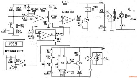
The eggs automatic incubator circuit is composed of the power supply circuit, temperature control circuit, temperature detection control circuit and egg timing turning circuit, and it is shown in Figure 4-2. Power supply circuit consists of the power switch S, power light HLl, power transformer T, bridge rectifier UR, filter capacitors C7-ClO and three-terminal voltage regulator integrated circuit IC2. Temperature detection control circuit consists of the resistors Rl-R6, capacitors Cl-C4, transistors Vl, V2, thermistor RT, thyristor VTl, heating lamp HL2 and heater EH. Vl uses 59013 or C8050, 3DG9013 silicon NPN transistor.
(View)
View full Circuit Diagram | Comments | Reading(2860)
Eggs automatic incubator 1
Published:2011/8/8 22:15:00 Author:Ecco | Keyword: Eggs automatic incubator
The eggs automatic incubator circuit is composed of the power supply circuit, automatic egg turning control circuit and temperature control circuit and other components, and it is shown in Figure 4-1. Power supply circuit is composed of the power switch Sl, fuse FU, power transformer T, rectifier diodes VDl-VD4, filter capacitors Cl, C2, resistors Rl, R2, power indicator LED VL2, voltage regulator VSl and power regulator diode VI. Rl-Rll select the 1/4W carbon film resistors or metal film resistors; Rl2 select the lW metal film resistor.
(View)
View full Circuit Diagram | Comments | Reading(2923)
High temperature disinfection cabinet
Published:2011/8/10 2:34:00 Author:Ecco | Keyword: High temperature , disinfection cabinet
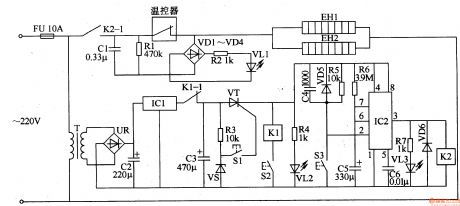
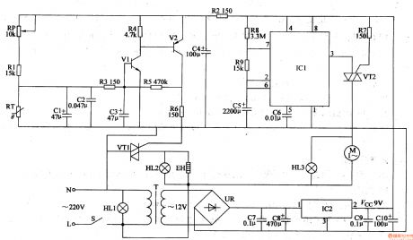
The high temperature disinfection cabinet circuit is composed of the power supply circuit, control circuit and indication circuit, and it is shown in Figure 3-210. Power supply circuit consists of the thermal fuse FU, power transformer T, bridge rectifier UR, three-terminal regulator IC lCl and filter capacitors C2, C3. Indication circuit is composed of the LEDs VLl-VL3, rectifier diodes VDl-VD4, resistors Rl, R2, R4, R7, step-down capacitor Cl and other components. The control circuit consists of the thyristor VT, relays Kl, K2, time-base integrated circuit lC2, control buttons Sl-S3, thermostat, resistors R3, R5, R6, diodes VD5, VD6 and zener diode VS.
(View)
View full Circuit Diagram | Comments | Reading(1311)
Fluorescent lamp electronic ballast
Published:2011/8/14 22:45:00 Author:Ecco | Keyword: Fluorescent lamp, electronic ballast
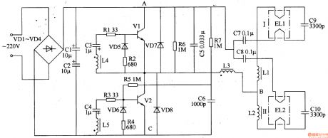
The fluorescent lamp electronic ballast circuit is composed of the rectifier filter circuit, high-frequency oscillator circuit and output circuit, and it is shown in Figure 3-202. Rectifier filter circuitis composed of the rectifier diodes VDl-VD4 and filter capacitors Cl, C2. High-frequency oscillator consists of the transistors VI, V2, resistors Rl-R7, capacitors C3, C4, C6, diodes VD5-VD8 and inductors L3-L5 (L3-L5 is wound in the same magnetic ring to form a high-frequency transformer). Output circuit consists of the chokes Ll, L2 (stabilizing current) and capacitors C7-ClO. Rl-R7 use 1/4W carbon film resistors or metal film resistors.
(View)
View full Circuit Diagram | Comments | Reading(9974)
UM95088 Telephone Circuit Diagram
Published:2011/8/9 18:30:00 Author:Vicky | Keyword: Telephone Circuit
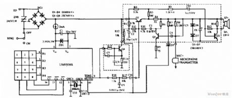
UM95088 telephone circuit diagram is shown in the above picture. UM95088 is specialized integrated module of dual tone multiple frequency for telephone dialing. It adopts the techniques of CMOS with dual-in-line package of 14 pins. Dual tone multiple frequency telephone schematic circuit made of the above IC, mainly comprises power supply, key board, dialing and transmitting network, and ad-dc coupling circuit (the ring circuit is omitted in the picture) etc. (View)
View full Circuit Diagram | Comments | Reading(11086)
Circuit diagram of memorial anti-toll-fraud alarm
Published:2011/8/9 20:47:00 Author:Vicky | Keyword: memorial anti-toll-fraud alarm
Memorial anti-toll-fraud alarm
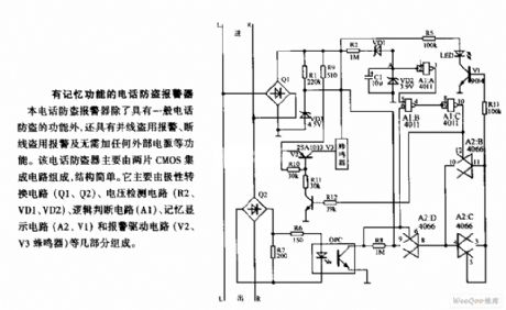
Despite the functions of general anti-toll-fraud telephone, the telephone anti-toll-fraud alarm has functions of alarm for toll fraud by doubling the line, and alarm for toll fraud by breaking the line. In addition, it does not need external power supply. The telephone anti-toll-fraud alarm is mainly composed by CMOS integrated circuit. The composition is very simple. It is mainly polarity reversing circuit (Q1 and Q2), voltage detection circuit (R2, VD1 and VD2), logic-judging circuit (A1), memory display circuit (A2 and V1), and alarm-driving circuit (V2 and V3 buzzer) etc. (View)
View full Circuit Diagram | Comments | Reading(1130)
| Pages:20/126 1234567891011121314151617181920Under 20 |
Circuit Categories
power supply circuit
Amplifier Circuit
Basic Circuit
LED and Light Circuit
Sensor Circuit
Signal Processing
Electrical Equipment Circuit
Control Circuit
Remote Control Circuit
A/D-D/A Converter Circuit
Audio Circuit
Measuring and Test Circuit
Communication Circuit
Computer-Related Circuit
555 Circuit
Automotive Circuit
Repairing Circuit