
Circuit Diagram
Index 1069
Dual Polarity Output Voltage Source Circuit of LM199
Published:2011/7/24 8:21:00 Author:Michel | Keyword: Output Voltage, Source Circuit
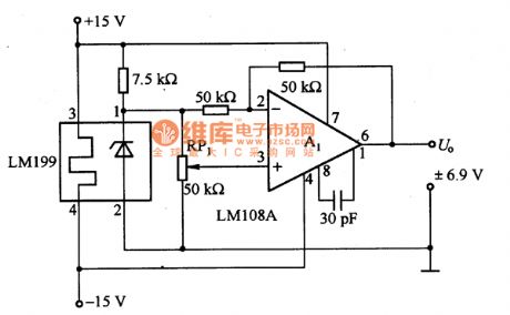
Dual polarity output benchmark voltage source circuit is as above.It outputs the benchmark voltage which is from negative to positive voltage.The LM199 heater is connected to ±15V power supply.RP1 is ten laps line potentiometer which alters its value to make the output change between +Uz~-Uz.Uz is the stability voltage in LM199 voltage regulating tube. A1 chooses LM1O8A operational amplifier and when it outputs positive voltage.A1 working condition is the same phase amplifier and A1 working condition is the inverse phase amplifier when it outputs inverse voltage. (View)
View full Circuit Diagram | Comments | Reading(765)
Binary Synchronous Counter Circuit of 74HC161
Published:2011/7/25 10:24:00 Author:Michel | Keyword: Binary, Counter Circuit
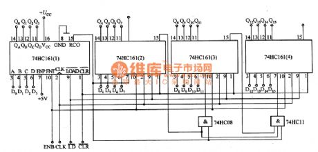
Picture 1 is binary synchronous counter circuit of 74HC161.It needs the counter which issynchronous with clock to get the real time counting result.When the highest clock frequency is input,the gate circuit is used,the front level (74HC161(1))RCO input is added to ENP of the last level (74 HCl61 (4).Therefore, the signal delay is determined by gate and it has nothing to do with counter so that the clock frequency is increased.In the circuit, the CLR, LD, CLK ENB are extra signals.When the CLR is low PWL,Qo一Q15 outputs low PWL.When ENB is high PWL,CLK rising edge is counting.
Picture 1:Binary Synchronous Counter Circuit of 74HC161
(View)
View full Circuit Diagram | Comments | Reading(4306)
Touching Type Sensor Touching Rod Type Circuit
Published:2011/7/29 9:12:00 Author:Robert | Keyword: Touching, Sensor, Rod
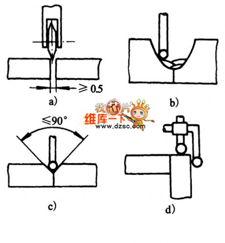
The picture shows the touching type sensor rod touching type circuit. (View)
View full Circuit Diagram | Comments | Reading(1034)
AC-Coupled Differential Amplification Principle Circuit
Published:2011/7/27 8:43:00 Author:Robert | Keyword: AC-Coupled, Differential, Amplification, Principle
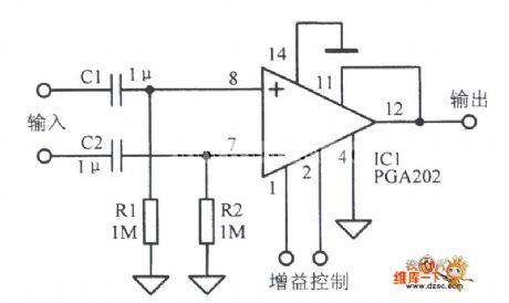
The picture shows the AC-coupled differential amplification principle circuit. (View)
View full Circuit Diagram | Comments | Reading(2517)
Smart Temperature Sensor MAX6698 With 7 Channels Circuit
Published:2011/7/28 6:38:00 Author:Robert | Keyword: Smart, Temperature, Sensor, 7, Channels
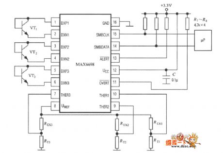
As shown, the MAX6698 could only fully connect three temperature-measuring transistors (VT1~VT3) and three thermistors (RT1~RT3). Its internal referenced voltage source UREF would supply for the three thermistors through the resistance REX1~REX3 separately. The voltage-drop would be send to pin of THER1~THER3 separately. The temperature-measuring transistor could select the CMPT3904, SST3904, KST3904-TF, SMBT3904, FMMT3904CT-ND and other types. (View)
View full Circuit Diagram | Comments | Reading(1259)
Enable_delay_tests
Published:2009/7/23 22:03:00 Author:Jessie
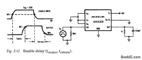
Figure 2-U shows a test circuit for measuring enable time for the MAX328/29. Typical enable turn-on time is 1μs for the MAX328/29M and 1.5μs for the MAX328/ 29C/E. (View)
View full Circuit Diagram | Comments | Reading(643)
BLOWN_FUSE_BLINKER
Published:2009/7/5 23:54:00 Author:May
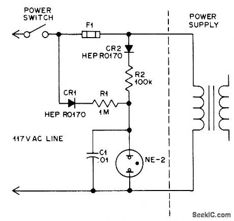
Neon,lamp NE-2 glows steadily when fuse is good and flashes when fuse opens. Flash rate, determined by R1 and C1, is about to flashes per second for values shown.-T.Lincoln, A Smart Blown-Fuse In.dicator, QST, March 1977, p 48. (View)
View full Circuit Diagram | Comments | Reading(958)
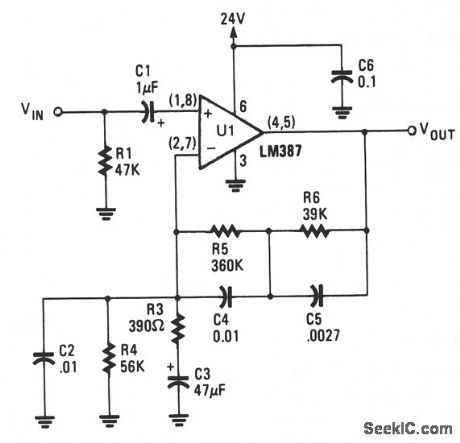
MAGNETIC_PHONO_PREAMPLIFIER
Published:2009/7/5 23:53:00 Author:May
View full Circuit Diagram | Comments | Reading(0)
Programmable Gain Buffer Amplification Circuit With Super Use Of Floating Exchange
Published:2011/7/30 19:41:00 Author:Robert | Keyword: Programmable, Gain, Buffer, Amplification, Super, Use, Floating Exchange
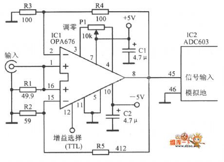
The picture shows the programmable gain buffer amplification circuit with super use of floating exchange. (View)
View full Circuit Diagram | Comments | Reading(509)
WIEN_SINE_WAVE
Published:2009/7/5 23:53:00 Author:May
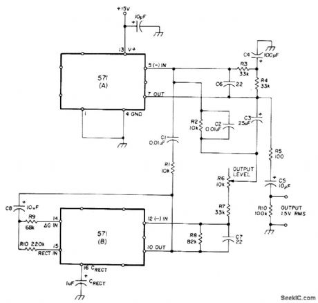
Uses NE571 analog compandor in oscillator circuit based on Wien network formed by R1-C1 and R2-C2, placed around output amplifier of section A to make it bandpass amplifier. Section B serves as inverting amplifier with nominal gain of 2. Total harmonic distortion is below 0.1%. Operating frequency is about 1.6 kHz for values shown, but can be varied from 10 Hz to 10 kHz. Frequency is l/21πRCforR = R1 = R2 and C = Cl = C2. R should be kept between 10K and 1 megohm and C between 1000 pF and 1 μF. Useful as fixed-frequency oscillator but can be tuned if matched dual pot is used for R1.R2.-W. G. Jung, Gain Control IC for Audio Signal Processing. Ham Radio, July 1977, p 47-S3. (View)
View full Circuit Diagram | Comments | Reading(1405)
A_C_TO_D_C_VOLTAGE_STANDARDIZATION
Published:2009/7/23 22:03:00 Author:Jessie
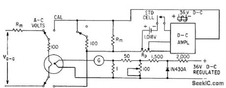
High-gain d-c amplifier is used in feedback circuit to standardize ct< voltages directly to standard cell.-E. A. Gilbert, Feedback Circuits for A-C Instrument Calibration, Electronics, 33:40, p. 94-96. (View)
View full Circuit Diagram | Comments | Reading(612)
5_V_FET_REGULATOR
Published:2009/7/5 23:52:00 Author:May
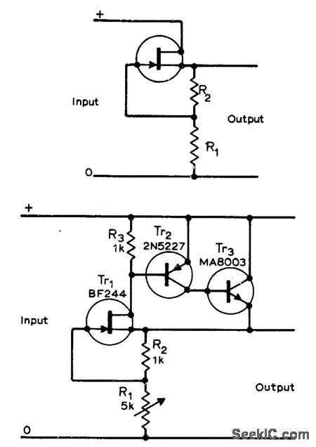
Output voltage changes less than 0.1 V for load current change from 0 to 60 mA. Output voltage changes caused by change in load resistance affect gate-source voltage of FET Tr1 via R1 and R2, causing compensating change in drain cument. Additional transistors serve to reduce output resistance and increase output current without affecting stabilization ratio of about 1000.-C. R. Masson, F.EJf. Voltage Regulator, Wireless World, Aug.1971, p 386. (View)
View full Circuit Diagram | Comments | Reading(672)
LINE_OPERATED_AMPLIFIER
Published:2009/7/5 23:52:00 Author:May
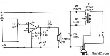
T1 isolates the unit from the line, and has a 24-V, center-tapped secondary. The output of the transformer is rectified by diodes D1 and D2 and filtered by capacitor C3 to provide 15 to 18 Vdc. The LM383 has built-in protection against speaker shorts. (View)
View full Circuit Diagram | Comments | Reading(1699)
Temperature/Voltage Monitoring System Circuit Composed Of MAX1298
Published:2011/7/31 20:36:00 Author:Robert | Keyword: Temperature, Voltage, Monitoring, System
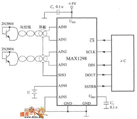
Ad shown in the picture, the circuit could measure two channels of temperature and one channel of battery voltage at the same time. It uses +5V power supply. The temperature sensor's wire shound need the shielded twisted pair. The shielded layer is connected to SHO pin. The C1 is a power noise-reduction capacitor. The C2 is used to filter output the noise of the referenced voltage. By using μC it could set the MAX1298's power working mode and read the MAX1298's output data, and also detect if the +5V power has the faults of under voltage or over voltage. (View)
View full Circuit Diagram | Comments | Reading(578)
TUNNEL_DIODE_TESTER
Published:2009/7/23 22:02:00 Author:Jessie
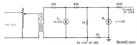
Curve-tracing circuit provides cro traces as aid in determining proper bias and circuit impedances for operating tunnel diode as switch, amplifier, or oscillator.-R. P. Murray, Biasing Methods for Tunnel Diodes, Electronics, 33:23, p 82-83. (View)
View full Circuit Diagram | Comments | Reading(864)
1_A_LAMP_FLASHER
Published:2009/7/5 23:52:00 Author:May
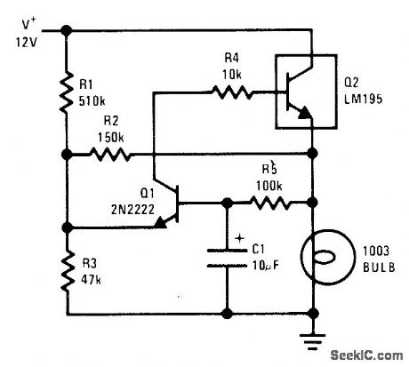
National LM195 power transistor is turned on and off once per second for flashing 12-V lamp. Current limiting in LM195 prevents high peak currents during turnon even though cold lamp can draw 8 times normal operating current. Current-limiting feature prolongs lamp life in flashing applications.-R.Dobkin, Fast IC Power Transistor with Thermal Protection, National Semiconductor, Santa Clara, CA, 1974, AN-110, p 5. (View)
View full Circuit Diagram | Comments | Reading(820)
SING_AROUND_TRANSMITTER
Published:2009/7/23 22:02:00 Author:Jessie
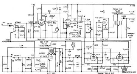
Used for precision measurement of ultrasonic velocity in liquids and solids. Transmit pulse is applied to ultrasonic transducer on one side of sample. Receiving transducer on other side generates signal to retrigger transmitter,with process repeating in sing-around fashion. Time and number of sing-around cycles are measured to get velocity.-R. L. Forgacs, Precision Ultrasonic Velocity Measurements, Electronics, 33:47, p 98-100. (View)
View full Circuit Diagram | Comments | Reading(796)
5_AND_15_V_SINGLE_CONTROL
Published:2009/7/5 23:52:00 Author:May
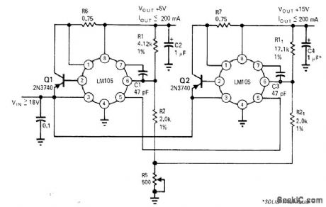
Single poten-tiometer serves for adjusting two reguiators simultaneously, Accuracy depends on output voltage differences of reguiators; error decreases when output voltages are closer Article gives design equation and covers other possiblesources of error.-R C Dobkin, One Adjustment Controls Many Regulators、EDN Magazine, Nov,1,1970 p33-35 (View)
View full Circuit Diagram | Comments | Reading(603)
MAGNETIC_TAPE_DATA_SAMPLER
Published:2009/7/23 22:02:00 Author:Jessie
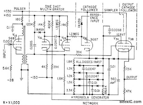
Used in playback system for discrimination of f-m signal from magnetic tape. Compares data channel signals with recorded reference frequency, to make output independent of tape speed. Tube V2B is cathode follower with hyperbola generator network as cathode impedance, to create curve for average area of voltage block at any time during data period for a given block width (1.4 millisec).-P. S. Bengston, Sampling Discriminators for Data Reduction, Electronics, 32:13, p 70-72. (View)
View full Circuit Diagram | Comments | Reading(725)
MICROPOWER_RADIOACTIVE_RADIATION_DETECTOR
Published:2009/7/5 23:51:00 Author:May
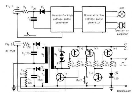
Circuit NotesIn the absence of radiation, no current is drawn. At normal background radiation levels the power consumption is extremely low. The instrument may be left on for several months without changing batteries. In this way the detector is always ready to indicate an increase in radiation. An LED is used as an indicator lamp. With background radiation it draws less than 50 μA ferrite pot core is used for the transformer with N1=30, N2=550, and N3=7. Using two 1.5V batteries with 0.5 Ah total capacity, the detector can work at background radiation levels for 0.5 Ah + 50μA=10,000 hours, which is more than a year. (View)
View full Circuit Diagram | Comments | Reading(1134)
| Pages:1069/2234 At 2010611062106310641065106610671068106910701071107210731074107510761077107810791080Under 20 |
Circuit Categories
power supply circuit
Amplifier Circuit
Basic Circuit
LED and Light Circuit
Sensor Circuit
Signal Processing
Electrical Equipment Circuit
Control Circuit
Remote Control Circuit
A/D-D/A Converter Circuit
Audio Circuit
Measuring and Test Circuit
Communication Circuit
Computer-Related Circuit
555 Circuit
Automotive Circuit
Repairing Circuit