
Circuit Diagram
Index 1077
VARIABLE_FLASHER_FOR_LED
Published:2009/7/5 22:46:00 Author:May
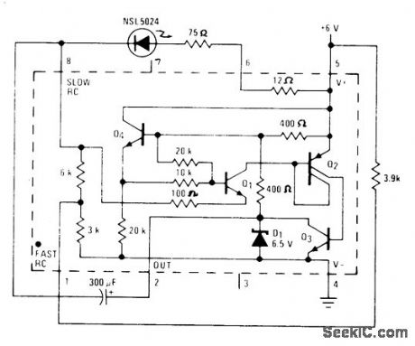
Terminal connections of National LM3909 flasher IC give choice of three different flash rates for LED used as indicator in battery portable equipment. Extemal resistors provide additional adjustments of flash rate. Appropriate connections to pins 1 and 8 make flash-controlling internal resistance 3K, 6K or 9K Flasher operates at any supply voltage above 2 V, with low duty cycle to give long battery life.-P. Lefferts, Power.Miser Flasher IC Has Many Novel Applications, EDN Magazine, March 20, 1976, p 59-66. (View)
View full Circuit Diagram | Comments | Reading(1346)
1_pF_TO_1_μF
Published:2009/7/5 22:46:00 Author:May
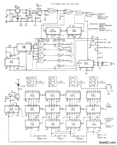
Presents instantly in digital form the value of unknown capacitor, in ranges of 1-9999 pF and 1-999.9 nF. Four digits are displayed, with leading-zero suppression and overflow indicator. Accuracy is better than 0.1% of full range ±1 digit for higher values in both ranges. Mono MVBR IC21 produces pulse whose length is directly proportional to value of CX plus about 980-pF total in CF. This pulse enables gate IC14D whose output goes to counter. Oscillator Q2, buffer Q3, dividers IC15 and IC16, and gates IC14 together give 40-MHz (range 1) or 400-kHz (range 2) pulses that are counted while IC21 holds IC14D open. Article covers construction in detail.-I. M. Chladek, Build This Digital Capacity Meter, 73Magazine, Jan. 1976, p 70-78. (View)
View full Circuit Diagram | Comments | Reading(1383)
Cheetah SUV ABS Circuit
Published:2011/8/1 10:45:00 Author:Robert | Keyword: Cheetah, SUV, ABS
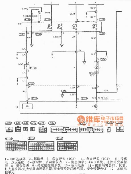
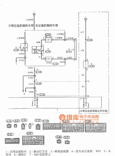
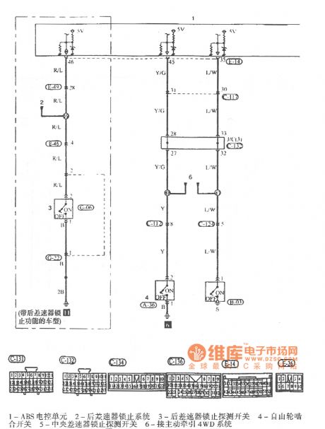
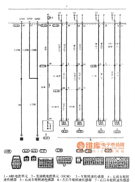
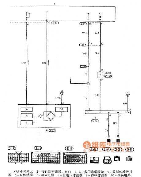
The pictures show the Cheetah SUV ABS circuits.
In the first picture the part 1 is IOD connector. The part 2 is fuse. The part 3 is ignition switch (IG2). The part 4 is ignition switch (IG1). The part 5 is connected to charging and ignition system. The part 6 is connected to the clock, multi-function meter. The part 7 is connected to active traction 4WD system and the remote-control variable shock absorber. The part 8 is instrument cluster. The part 9 is connected to the constant speed control system. The part 10 is standby power. The part 11 is connected to brake alarm lamp, meter, light monitor, ignition key not pulling reminder, seat belt alarm lamp. The part 12 is connected to the ABS ECU. And so on. (View)
View full Circuit Diagram | Comments | Reading(608)
TRANSMITTER_FOR_REMOTE_TERMINAL
Published:2009/7/5 22:45:00 Author:May
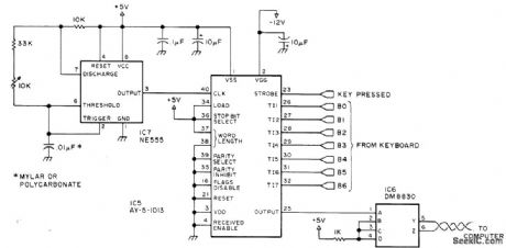
Consists of AY-5-1013 UART attached to keyboard, with twisted-pair cable running to receiver unit at computer location. Coaxial extension cable for monitor is only other connection to computer system because terminal has own power supply. Transmission is in one direction only. NE555 oscillator is set at 1760 Hz ± 1% with aid of frequency counter, for 110-b/s serial rate. IC6 is 5-V National DM8830 differential line driver or equivalent. Pin 14 of IC6 goes to +5 V and pin 7 to ground.-S. Ciarcia, Come Upstairs and Be Respectable, BYTE, May 1977, p 50-54. (View)
View full Circuit Diagram | Comments | Reading(1627)
Off_leakage_current_tests
Published:2009/7/23 21:54:00 Author:Jessie
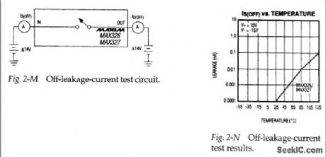
Figure 2-M shows a basic test circuit for measuring off-leakage-current I S(OFF) and I D(OFF) for the MAX326/27. Figure 2-N shows how I S(OFF) changes with temperature (View)
View full Circuit Diagram | Comments | Reading(756)
PCD3341 Microcomputer Dialing Integrated Circuit
Published:2011/7/28 23:02:00 Author:Michel | Keyword: Microcomputer Dialing, Integrated Circuit
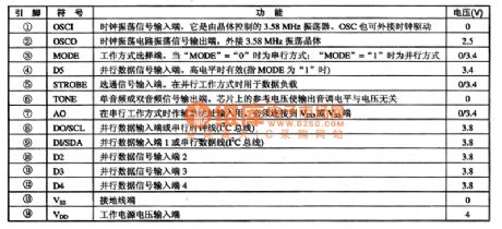
PCD3341 is the microcomputer integrated circuit, it is designed for communication equipment control and display, redial and storage dialing.
First,Functions Features
PCD3341 integrated circuit contains oscillator, keyboard input unit,column keyboard input unit, I2C bus interface control: ROM address counter,the ROM 3 KB read memory, ARM address counter,RAMM224KB read-only memory,eight timing counter, accumulators and test logic circuit, reset circuit,instruction registeration: control logic and interrupting logic etc .It uses an 8 bit CPU CPU, 224 KB of RAM, the 3KB programmable ROM,thus it saves energy very much. (View)
View full Circuit Diagram | Comments | Reading(697)
EMITTER_COUPLED_BIG_LOOP_OSCILLATOR
Published:2009/7/5 22:45:00 Author:May
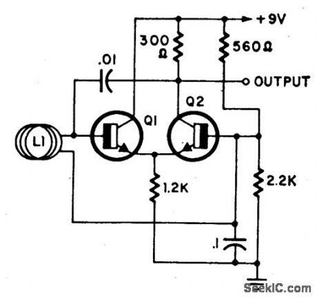
L1 is a loop of 10 to 20 turns of insulated wire with a diameter anywhere between 4 to 4'. Oscillator frequency (7 to 30 MHz) shifts substantially when a person comes near or into the loop. This oscillator together with a reso-nant detector might make a very good anti-personnel alarm. Transistors are 2N2926 or equivalent. (View)
View full Circuit Diagram | Comments | Reading(1023)
The constitution circuit diagram of portable rapid pulse generator
Published:2011/6/30 5:39:00 Author:Rebekka | Keyword: portable rapid pulse generator, constitution circuit
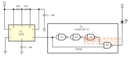
Since the whole TTL series is the lack of a high-speed monostable multivibrator and the ECL requires a small voltage swing and a small range power supply. It drives us to use F series of gates which has fast transition time and small transmission time delay. This requires making a small portable fast pulse generator. It is used to test the high-speed photomultiplier that used in the study of gamma-ray astronomy. The use of only two integrated circuit is to help reduce the consumption and narrow the size(Figure 1). Output the pulse is width from the output gate G4 in IC2. The pulse width is less than 10ns and the rise and fall time of the normal high pulse is about 2.5ns. It is equivalent to the delay of three gates. These pulses are very suitable for decrease the cathode potential of HLMP-CB-15-speed blue LED. But the anode of LED is clamped to 5V. G4 forces almost the entire 5 V supply voltage adding to the LED, so that the large voltage swingof the LED which is printed on circuit board solder connecting to the edge has the best brightness. The rechargeable battery is fixed at the other side of the printed circuit board. The circuit uses CMOS timer IC1, it only costs less than 4 mA of current.
(View)
View full Circuit Diagram | Comments | Reading(2019)
SEQUENTIAL_AC_FLASHER
Published:2009/7/5 22:44:00 Author:May
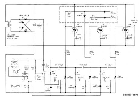
Uses simple ring counter in which triac gates form part of counter load. Incandescent lamps come on in sequence, with only one lamp normally on at a time. Pulse rate for switching lamp can be adjusted from about 1 every 0.1 s to 1 every 8 s.Circuit enclosed in dashed rectangle can be added to keep previous lamps on when next lamp is turned on. Only three stages are shown, but any number of additional stages can be added.- Circuit Applications for the Triac, Motorola, Phoenix, AZ, 1971, AN-466 p 11.
(View)
View full Circuit Diagram | Comments | Reading(1640)
Santana 2000 Series M1.5.4 Engine Circuit
Published:2011/8/2 2:53:00 Author:Robert | Keyword: Santana, M1.5.4, Engine
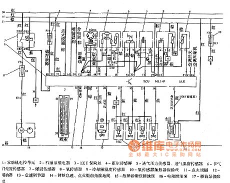
The picture shows the Santana 2000 series M1.5.4 engine circuit.
In the picture the part 1 is engine ECU. The part 2 is fuel pump relay. The part 3 is ECU fuse. The part 4 is hall sensor. The part 5 is intake air pressure sensor. The part 6 is throttle position sensor. The part 7 is knock sensor. The part 8 is oxygen sensor. The part 9 is cooling fluid temperature sensor. The part 10 is oxygen sensor heater fuse. The part 11 is ignition coil. The part 12 is injector. The part 13 is idle speed regulator. The part 14 is used to adjust the idle speed, ignition advance angle and then it is connected to the ground. The part 15 is fault diagnosis device and it is connected to ground. The part 16 is electric fuel pump. The part 17 is fuel pump fuse. (View)
View full Circuit Diagram | Comments | Reading(1611)
10_pF_TO_1000_μF_DIGITAL
Published:2009/7/5 22:44:00 Author:May
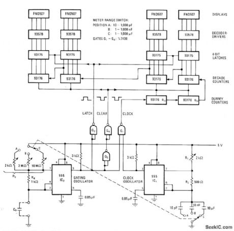
Uses 555 timers as free-runnlng oscillators, one for gating and other as clock driving digital counter having fairchild FND507 4-digit display,Arrangement gives good accuracy without use of crystal oscillator,-W.H. Wang,Low-Cost Oscillators Build Accurate Capacitance Meter,Electronics,May 26, p 127 and 129. (View)
View full Circuit Diagram | Comments | Reading(647)
SWITCH_CONTROLLED_ADDER
Published:2009/7/5 22:44:00 Author:May
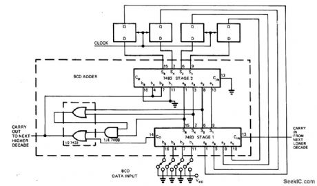
Direct BCD input from thumbwheel switch and use of standard crystal frequencies are primary advantages of accumulator stage of synthesizer, one decade of which is shown. BCD adder drives four D flip-flops whose outputs are fed back and added to switch states. Frequency range depends on number of decades used. Output pulse may be used directly for synchronization.If square wave is needed, clock frequency can be doubled and output of accumulator used to clock flip-flop.-D. W. Coulboum, Set Frequency Synthesizer with Thumbwheel Switches, EDN Magazine, April 5, 1975, p 115 and117. (View)
View full Circuit Diagram | Comments | Reading(3210)
RF_GENIE
Published:2009/7/5 22:43:00 Author:May
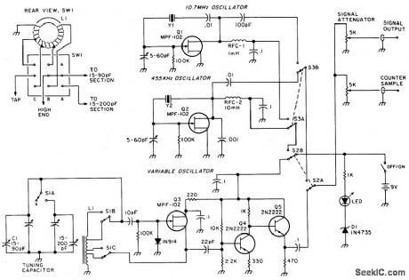
A variable oscillator covers 3.2 to 22 MHz in two bands-providing coverage of 80 through 15 meters plus most crystal-filter frequencies. Optional455 kHz and 10.7 MHz crystal oscillators can be switched on-line for precise tf alianmen' generator output is on the order of 4 volts p-p into a 500 ohm load. A simple voltage-divider attenuator controls the generator's output level, and a second output provides sufficient drive for an external frequency counter. (View)
View full Circuit Diagram | Comments | Reading(2279)
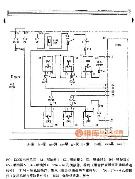
Hongqi Century Star Engine Circuit
Published:2011/8/2 8:22:00 Author:Robert | Keyword: Hongqi, Century Star, Engine
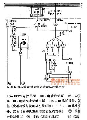
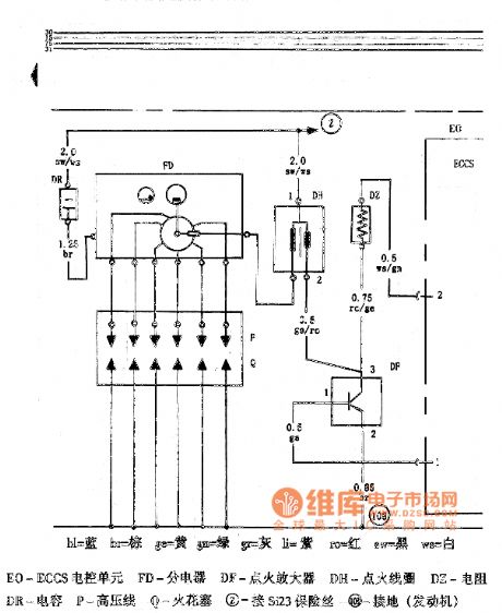
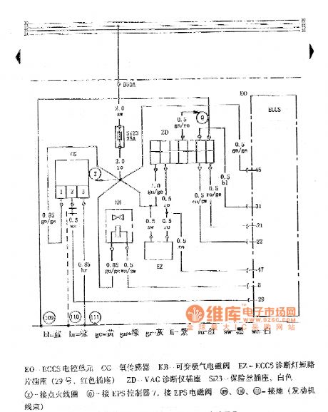
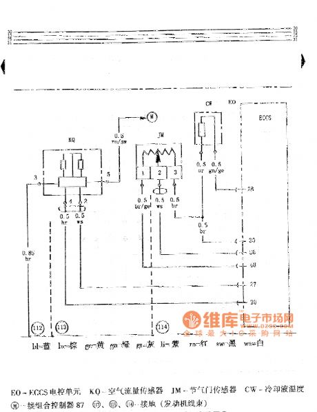
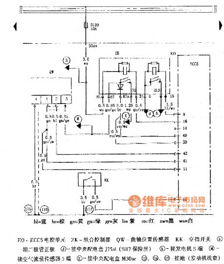
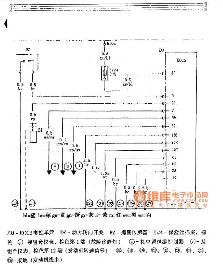
The pictures shown the Hongqi Century Star engine circuits.
In the first picture, the EO is ECCS ECU. The DB is electric fuel pump. The DS is AAC value. The BJ is electric fuel pump relay. The T10 is 10-hole connector and its colour is yellow (engine wire and engine left wire is connected). The T'10 is 10-hole connector and its colour is blue (engine left wire and the dashboard wire is connected).In the second picture the EO is ECCS ECU. The E1 is oil injector 1. The E2 is oil injector 2. The E3 is oil injector 3. The E4 is oil injector 4. The E5 is oil injector 5. The E6 is oil injector 6. The T26 is a 26-hole connector which is brown (instrument cluster socket engine speed signal). The T'26 is a 26-hole connector which is black (instrument cluster socket car speed signal). The T4, T'4 are 4-hole connectors (engine wire and oil injector is connected). The Si25 is fuse socket which is gray. And so on. (View)
View full Circuit Diagram | Comments | Reading(733)
20_20000_Hz
Published:2009/7/5 22:42:00 Author:May
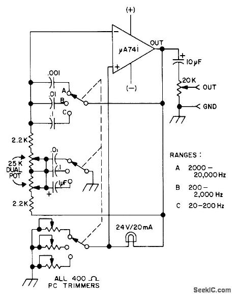
Wide-range audio oscillator covers AF spectrum in three switch-selected ranges, with harmonic distortion as low as 0.15%, for quick checks of audio equipment. Drain is only 6 mA from two 9-V batteries. Circuit is Wien-bridge oscillator using 741 opamp. Article covers construction and calibration, including optional connection for operation from single 9-V battery with AF output reduced to 2 V.-J. J. Schultz, Wide Range IC Audio Oscillator, 73 Magazine, Jan. 1974, p 25-28. (View)
View full Circuit Diagram | Comments | Reading(971)
GAS_SMOKE_DETECTOR_WITH_BEEPING_HORN
Published:2009/7/5 22:42:00 Author:May
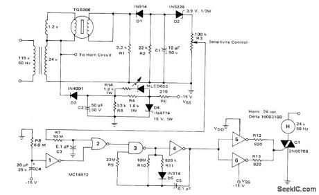
Taguchi TGS308 gas sensor increases voltage across R3 when sensor conductivity is increased by combustible gases. After time delay provided to prevent power tumon false alarms, CMOS astable MVBR using gates 3 and 4 is energized to fire triac and drive AC horn to give distinctive repetitive sound lasting about 2.5 s, with 0.2-s intervals between beeps. Triac gate drivers operate from -15 V supplyderived from 24-V winding of power transformer.-A.Pshaenich, Solid State Gas/Smoke Detector Systems, Motorola, Phoenix, AZ, 1975, AN-735, p 6. (View)
View full Circuit Diagram | Comments | Reading(2461)
MALFUNCTION_ALARM
Published:2009/7/5 22:42:00 Author:May
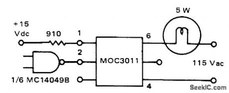
Motorola MOC3011 optoisolator serves as interface between CMOS logic of microprocessor and 5-W 115-VAC lamp.Input logic is connected to energize infrared LED of optoisolator by providing up to 50 mA.Once triggered, indicator lamp remains on until current drops below holding value of about 100 μA.-P. O'Neil, Applications of the MOC3011 Triac Driver, Motorola, Phoenix, AZ, 1978, AN-780,p2. (View)
View full Circuit Diagram | Comments | Reading(1136)
DC Voltage Meter Wiring Method Circuit
Published:2011/8/2 8:55:00 Author:Robert | Keyword: DC, Voltage, Meter, Wiring, Method
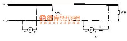
The picture shows the DC voltage meter wiring method circuit.
The voltage meter is used to measure the voltage of electrical line voltage. When measuring it could connect the voltage meter directly to the circuit, which is shown in the picture. When wiring it should be noted that the positive and negative polar of the voltage meter and the wire's positive and negative polar should be corresponding. It the voltage meter measurement mechanism's internal resistor R is not large enough, and also the measurement voltage is a little higher, in this case it should add a serial resistor R to reduce the meter mechanism's voltage. The resistor in this circuit is also called voltage doubler. (View)
View full Circuit Diagram | Comments | Reading(624)
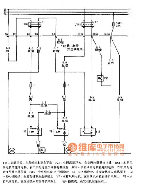
2.5L Engine Control Sensor and Computer Connection Circuits of Beijing CHEROKEE Light Off-road Vehicle
Published:2011/7/24 7:35:00 Author:Michel | Keyword: CHEROKEE, Light Off-road Vehicle, Sensor, Computer Connection

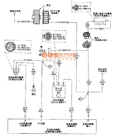
In the picture, the engine controller (ECU) local is drawn up.The feet is connected to synchronous sensor. The end face plug-and-socket of the sensors express the wire location and its position in the manual can be checked.The plug has more than one contacting point and K4 belongs to the engine control (ECU) circuit.And computer has 8V power supply crankshaft position sensor and synchronous sensor. (View)
View full Circuit Diagram | Comments | Reading(884)
TDA2003 Reference Material Circuit
Published:2011/7/30 9:02:00 Author:Robert | Keyword: Reference, Material
The features of TDA2003:The TDA2003's current output capacity is strong and also it has low harmonic distortion and crossover distortion. Its every pin has the AC and DC short circuit protection and it could be used safely. The voltage on the load could get 40V.The TDA2003's pin function and pin definition.The maximum rated value Tamb=25.Parameter name, symbol, ultimate value, unit.power peak voltage (50ms), Vccp, 40, V.DC power voltage, Vcc, 28, V.Working power voltage, Vcc, 18, V.Output repetitive peak voltage, Io, 3.5, A.Output not repetitive peak voltage, Io, 4.5, A.Power consumption T=90, PD, 20, W.Storage temperature, Tstg, -40, +150, degree.Welding temperature, Tj, -40, +150, degree. (View)
View full Circuit Diagram | Comments | Reading(836)
| Pages:1077/2234 At 2010611062106310641065106610671068106910701071107210731074107510761077107810791080Under 20 |
Circuit Categories
power supply circuit
Amplifier Circuit
Basic Circuit
LED and Light Circuit
Sensor Circuit
Signal Processing
Electrical Equipment Circuit
Control Circuit
Remote Control Circuit
A/D-D/A Converter Circuit
Audio Circuit
Measuring and Test Circuit
Communication Circuit
Computer-Related Circuit
555 Circuit
Automotive Circuit
Repairing Circuit