
Circuit Diagram
Index 768
MEASURING_TRANSISTOR_TRANSFER_RATIO
Published:2009/7/17 2:15:00 Author:Jessie
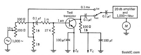
Basic test circuit shown measures small-signal short-circuit forward current transfer ratio of transistors. Gives direct reading of h-fe when base current is held at fixed value of 1 microamp.-Texas Instruments Inc., Transistor Circuit Design, McGraw-Hill, N.Y., 1963, p 70. (View)
View full Circuit Diagram | Comments | Reading(924)
THERMAL_CONSTANTS_OF_TRANSISTORS
Published:2009/7/17 2:14:00 Author:Jessie
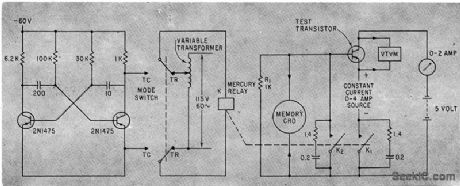
Astable mvbr generates 0.3-sec pulse every 3 sec to drive mercury relay when mode switch is on IC contacts for measuring thermal lime constant of transistor under test. Constant power is applied between pulses, using cro as guide for keeping power level near normal steady-state value of transistor. Thermal resistance data is obtained with mode switch on contact TR, where 60-cps supply drives relay.-H. Bauman, Practical Way to Measure Transistor Thermal Resistance, Electronics, 36:7, p 66-67. (View)
View full Circuit Diagram | Comments | Reading(772)
MOISTURE_METER
Published:2009/7/17 2:13:00 Author:Jessie
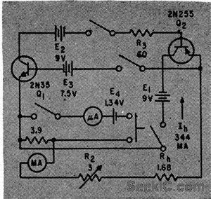
Maintains constant current for 20 minutes of heavy loading of conventional zinc-carbon dry cells when measuring moisture in pulverized coal or other powders, through use of inverse voltage feedback in two-stage direct-coupled amplifier.-G. E. Fasching, Inverse Feedback Stabilizes Dry Cell Current Sources, Electronics, 32:41, p 78. (View)
View full Circuit Diagram | Comments | Reading(856)
CHARGE_PUMP_GENERATING_GATE_DRIVE
Published:2009/7/17 2:13:00 Author:Jessie
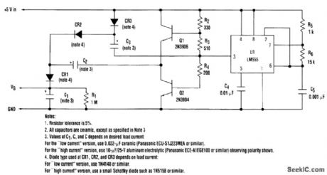
A charge pump built as a voltage tripler can provide just the right amount of voltage needed for gate drive in a 5-V system. (View)
View full Circuit Diagram | Comments | Reading(864)
15_V_AT_600_mA
Published:2009/7/17 2:13:00 Author:Jessie
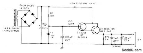
Developed for 2-meter FM transceiver used as repeater. Output voltage is well filtered. Regulator allows voltage to drop only 0.1 V when repeater goes from standby to transmit. Use heatsink on 2N3055 series-regulator transistor.-H. Cone, The Minirepeater, 73 Magazine, June 1975, p 55-57, 60-62, and 64-65. (View)
View full Circuit Diagram | Comments | Reading(1174)
CEMENT_SETTING_TIMER
Published:2009/7/17 2:11:00 Author:Jessie
Sample of cement is inserted as dielectric material in test-tube capacitor, and admittance readings are made every 15 minutes using 7-Mc crystal oscillator with anode circuit tuned to 28Mc.Maximum admittance indicates end of setting process.-J. M. Tobio, Electronics Determines Cement Setting Time, Electronics, 31:41, p 88-90. (View)
View full Circuit Diagram | Comments | Reading(838)
4013_DIVIDE_BY_2_CIRCUT
Published:2009/7/17 2:11:00 Author:Jessie
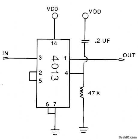
The first pulse into the input drives the output high. The second pulse drives the output low. VCC can be 5 to 15 V. (View)
View full Circuit Diagram | Comments | Reading(2152)
VOLTAGE-TO_FREQUENCY_CONVERTER_II
Published:2009/7/11 5:24:00 Author:May
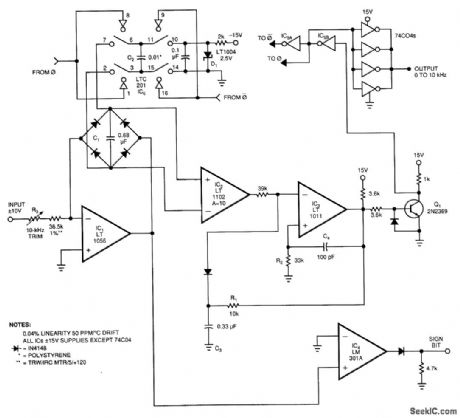
This voltage-to-frequency converter (VFC) accepts the bipolar-ac inputs. For -10- to + 10-V inputs, the converter produces a proportional 0- to 10-kHz output. Linearity is 0.04%, and temperature coefft-cient (TC) measures about 50 ppm/ °C.To understand the circuit, assume that its input sees a bipolar square wave. During the input's positive phase, IC1's output swings negative and drives current through C1 via the full-wave diode bridge. IC1's current causes C1's voltage to ramp up linearity. Instrumentation amplifier IC2 operates at a gain of 10 and measures the differential voltage across C1.IC2's output biases comparator IC3's negative input. When IC2's output crosses zero, IC3 fires ac positive feedback to IC3's positive input and hangs up IC3's output for about 20 μs. The Q1 level shifter drives ground-referred inverters IC5A and IC5B to deliver biphase drive to LT1004 switch IC6.IC6, configured as a charge pump, places C2 across C1 each time the inverters switch, which resets C1 to a lower voltage. The LT1004 reference (D1), along with C2's value, determines how much charge the charge pump removes from C1 each time the charge pump cycles. Thus, each time IC2's output tries to cross zero, the charge pump switches C2 across C1, which resets C1 to a small negative voltage and forces IC1 to begin recharging C1. The frequency of this oscillatory behavior is directly proportional to the input-derived current into IC1. During the time that C1 is ramping toward zero, IC6, places C2 across the reference diode (D1), and prepares C2 for the next discharge cycle. The action is the same for negative-input excursions, except that IC1's output phasing is reversed. IC2, looking differentially across IC1's diode bridge, sees the same signal as it does for positive inputs; therefore, the circuit's action is identical. IC4, detecting IC1's output polarity, provides a signal bid output. (View)
View full Circuit Diagram | Comments | Reading(1685)
VIDEO_SELECTOR
Published:2009/7/11 5:22:00 Author:May
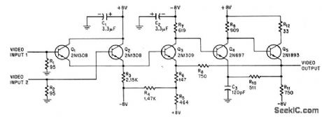
Selects largest of several positive-going video signals as positive-going output to 95-ohm load. Circuit gain is about 3 db.-A. E. Popodi, Reliable Repertoire of Display Circuits Electronics.38:2,p60-66 (View)
View full Circuit Diagram | Comments | Reading(1419)
28_MHz_TO_55_MHz
Published:2009/7/11 5:18:00 Author:May
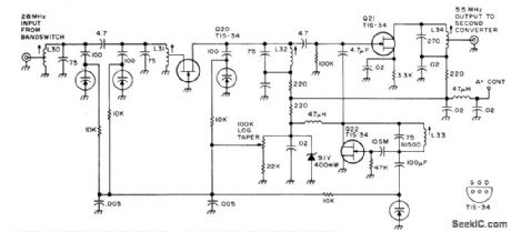
Contains bandpass filter, grounded-grid RF stage Q20, mixer Q21, and oscillator Q22, with all tuning accomplished by variable-capacitance diodes. Oscillator covers 22.5 to 24.5 MHz. Used in all-band double-con-version superheterodyne receiver for AM, nar-row-band FM, CW, and SSB operation. Supply is 13.6 V regulated. Article gives all circuits of receiver. -D.M Eisenberg, Build This All-Band VHF Receiver, 73 Magazine, Jan 1975, p 105-112 (View)
View full Circuit Diagram | Comments | Reading(726)
PULSE_COMPARATOR_FOR_TAPE_READER
Published:2009/7/11 5:18:00 Author:May
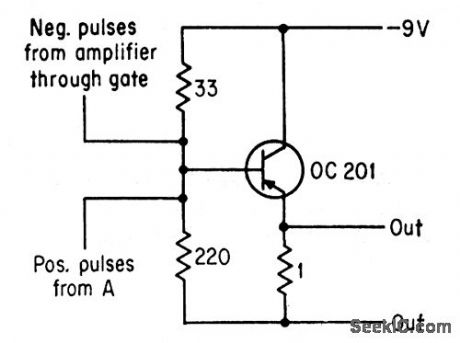
With hole in front of photocell, negative pulse into comparator is much larger than positive drive pulse obtained from GaAs lamp circuit, and comparator delivers negative output pulse.With no hole and no negative pulse, comparator output is positive but same magnitude, because amplifier negative pulses are twice as large as positive input pulses.-R. F. Broom and C. Hilsum, Diode lamp Makes Tope Readers Faster, Electronics, 36:20, p44-45. (View)
View full Circuit Diagram | Comments | Reading(758)
ECHO_SYSTEM_DYNAMIC_RANGE_BOOSTER
Published:2009/7/17 2:10:00 Author:Jessie
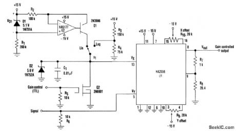
Using a variable-gain preamplifier helps improve the dynamic range of echo systems. Here, Harris Semiconductor's HA2556 multiplier is used to implement the variable-gain preamplifier and establish the signal bandwidth and noise figure. An echo sys-tem with a fixed-gain preamplifier exhibits poor dynamic range because close targets (long return times) have high signal amplitudes, whereas distant targets (long return times) produce amplitudes that are much lower. One solution involves a preamplifier that has a gain that is proportional to time so that the gain witl be small for close targets and large for dislant targets. The preamplifier must meet all of the other preamplifier criteria, such as bandwidth and noise performance. Moreover, the added time-dependent gain function must not degrade the signal. This type of variable-gain preamplifier can be built with a multiplier IC, the Harris Semiconductor HA2556. This IC establishes the signal bandwidth and noise figure because it is the only component in the signal path. The HA5177 op amp and its associated circuitry make up a constant-current source with a current (I) of VD1/R2=51μA. If the switch (S1) is in the LINEAR-position with Q2's gate held high, the cur-rent source is shorted to ground by Q2 and the multiplier gain is set to zero. When the transmission of the outgoing signal is complete, Q2's gate is brought low, forcing it into a very high drain resistance state (almost an open circuit). Consequently, the HA5177 current can charge C1 in a linear manner. The voltage across 01 then ramps up from 0 to 5V in 1 ms. During the first portion of the ramp, when the returned signal is very large, the multiplier gain is small because VX, is small. As time increases, so does VX providing more gain through the multiplier as the expected echo decreases in amplitude. As a result, the output-voltage swing of the multiplier tends to stay constant for large changes in input signal. In addition, the dynamic range is improved to the amount of the ramp change, which is more than 60 dB with the values shown in the figure. (View)
View full Circuit Diagram | Comments | Reading(1574)
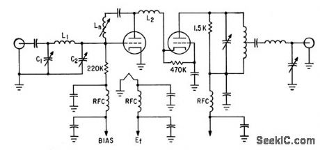
MIXER_FOR_DISTORTION_MONITOR
Published:2009/7/17 2:09:00 Author:Jessie
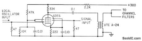
Combines local oscillator signal with two input-frequency tones without introducing distortion, by using primarily grid-swamping techniques.-G. H. Smith, Distortion Monitor Checks Linear Amplifier Characteristics, Electronics, 34:27, p 57-59. (View)
View full Circuit Diagram | Comments | Reading(691)
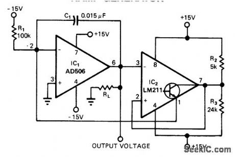
STEPPED_WAVEFORM_GENERATOR
Published:2009/7/17 2:08:00 Author:Jessie
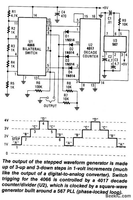
A decode counter(U2) is used to perform sequential switching vla a CD 4066.Analog switch is togenerate a waveform. The clock is a 567 PLL or otherVCO chip. (View)
View full Circuit Diagram | Comments | Reading(1666)
COMMON_EMITTER_BETA_TEST_SET
Published:2009/7/17 2:08:00 Author:Jessie
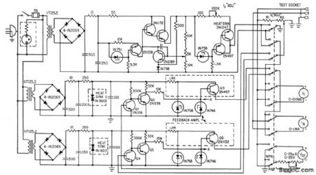
Switch permits testing both npn and pnp transistors over wide current and voltage ranges. Two feedback amplifiers are used, one for npn and the other for for pnp.-R . M. Mann, Fresh Approach to Measuring Transistor Beta Electronics,36:30,p 47-49 (View)
View full Circuit Diagram | Comments | Reading(816)
SAWTOOTH_GENERATOR_FOR_SWEEP_GENERATORS
Published:2009/7/17 2:07:00 Author:Jessie
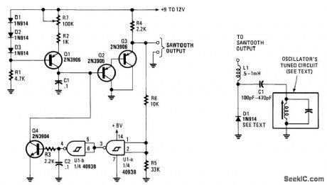
This circuit will generate a linear sawtooth between 30 Hz and 3000 Hz. Q1 is a constant-current source that charges C1 until the output level at Q3 emitter triggers U1A and U1B, which turns on Q4 and discharges C1. The frequency range can be varied by changing the value of C1. This circuit should be good to several tens of kHz.
(View)
View full Circuit Diagram | Comments | Reading(920)
RAMP_GENERATOR
Published:2009/7/17 2:06:00 Author:Jessie
Providing a 0-to 10-V excurslon from 0.4 Hz to 100 kHz,this circuit offers both simplicity and smallslze.The negative current through R1 produces the ramp's positive slope and causes the output of IC1 to increase linearly toward the+15-V rail. (View)
View full Circuit Diagram | Comments | Reading(2907)
MEASURING_CONVERSION_GAIN
Published:2009/7/17 2:05:00 Author:Jessie
Used form measuring input impedance characteristics of high-frequency transistor for operation beyond cutoff in special converter circuits.-V.W.Vodicka and R.Zuleeg, Transistor Operation Beyond cutoff Frequency, Electronics,33:35,p 56-60. (View)
View full Circuit Diagram | Comments | Reading(825)
SIMPLE_STAIRCASE_GENERATOR
Published:2009/7/17 2:05:00 Author:Jessie
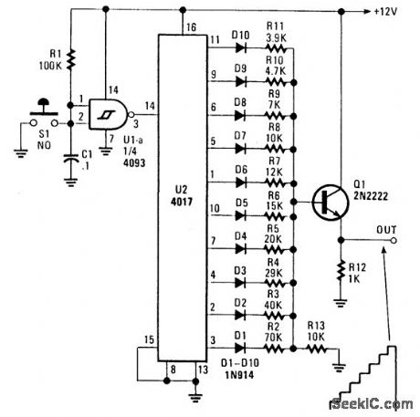
U2 is a decade counter /divider. U1 is used as a switch debouncer. For a self-generating system, connect a resistor between pins 2 and 3 of a U1 value that should be between 10 kΩ and several MΩ, depending on desired frequency. C1 can also be varied to change frequency. Also, S1 can be omitted in the self-generating version. (View)
View full Circuit Diagram | Comments | Reading(2448)
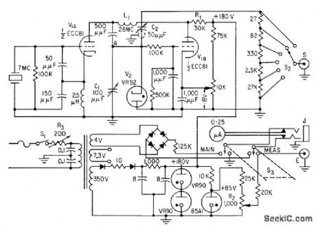
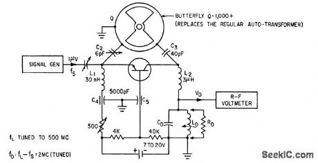
NOISE_FIGURE_MEASUREMENT_OF_R_F_TUBES
Published:2009/7/17 2:04:00 Author:Jessie
Standardized EIA Committee circuit measures noise-figure of cascode r-f amplifiers with 95% repeatability Jig circuit for ,tube under lest has 200-Mc center frequency and 10-Mc bandwidth,-T .E. Gausman, Standardizing Noise-Figure Measurement, Electronics,36:1,p 124-129. (View)
View full Circuit Diagram | Comments | Reading(886)
| Pages:768/2234 At 20761762763764765766767768769770771772773774775776777778779780Under 20 |
Circuit Categories
power supply circuit
Amplifier Circuit
Basic Circuit
LED and Light Circuit
Sensor Circuit
Signal Processing
Electrical Equipment Circuit
Control Circuit
Remote Control Circuit
A/D-D/A Converter Circuit
Audio Circuit
Measuring and Test Circuit
Communication Circuit
Computer-Related Circuit
555 Circuit
Automotive Circuit
Repairing Circuit