
Circuit Diagram
Index 898
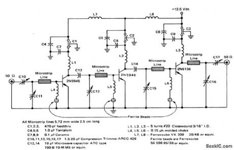
13_vatt_microstrip_UHF_amplifier_for_220_to_225_MHz
Published:2009/7/20 7:22:00 Author:Jessie
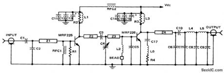
13-vatt microstrip UHF amplifier for 220 to 225 MHz (ouurtesy Motorola Semiconductor Products Inc.). (View)
View full Circuit Diagram | Comments | Reading(1041)
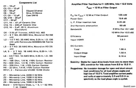
160_watt_PEP_broadband_linear_amplifier_for_28_volt_operation_
Published:2009/7/20 7:20:00 Author:Jessie

160-watt PEP broadband linear amplifier for 28-volt operation (courtesy Motorola Semiconductor Products Inc.). (View)
View full Circuit Diagram | Comments | Reading(1035)
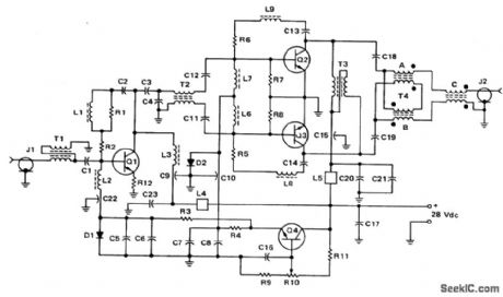
Two_stage_80_watt_RF_poweramplifier_for_144_to_175_MHz_FM_operation
Published:2009/7/20 7:18:00 Author:Jessie
Two-stage 80-watt RF poweramplifier for 144 to 175 MHz FM operation. About 5.5 watts ofdrive are required torthe rated output (courtesy Motorola Semiconductor Products Inc.). (View)
View full Circuit Diagram | Comments | Reading(1226)
LAMP_CONTROL
Published:2009/7/20 7:17:00 Author:Jessie
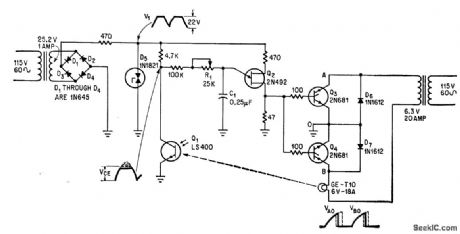
Phototransistor Q1 senses lamp intensity and controls firing angle of scr's Q3 and Q4 through unijunction transistor Q2.-R. L. Carvajal, Phototransistor Regulates Illumination Intensity, Electronics, 38:20, p 101. (View)
View full Circuit Diagram | Comments | Reading(977)
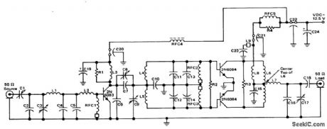
80_watt_PEP_broadband_linear_amplifier_for_125_volt_operation
Published:2009/7/20 7:15:00 Author:Jessie
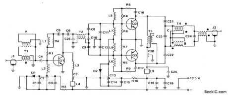
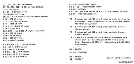
80-watt PEP broadband linear amplifier for 12.5-volt operation (courtesy Motorola Semiconductor Products Inc.) (View)
View full Circuit Diagram | Comments | Reading(999)
PHOTOMULTIPLIER_FOR_GAMMA_RAY_SPECTROMETER
Published:2009/7/20 7:13:00 Author:Jessie
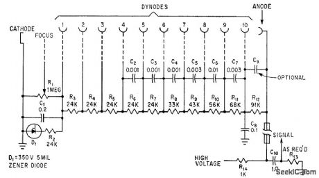
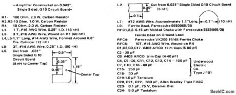
Flashes of light from scintillator crystal are picked up by EM19579 photomultiplier to measure underwater gamma radiation, and amplified output of photomultiplier is fed to surface equipment through coaxial cable that also serves as 2,000-V high-voltage lead for anode.-G. K. Riel, New Underwater Gamma Spectrometer, Electronics, 36:10, p 56-8. (View)
View full Circuit Diagram | Comments | Reading(1202)
Balanced_modulator_circuit_using_an_MC1596G
Published:2009/7/20 7:13:00 Author:Jessie
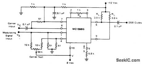
Balanced modulator circuit using an MC1596G. For a maximum modulating signal input of 300 mV RMS, the suppression of spurious sideband is typically 55 dB at a carrier frequency of 500 kHz (courtesy Motorola Semiconductor Products Inc.). (View)
View full Circuit Diagram | Comments | Reading(2369)
30_MHz_RF_amplifier_with_limiting_using_the_EGC703A_10
Published:2009/7/20 7:12:00 Author:Jessie
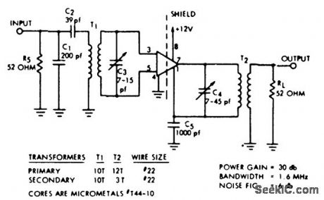
30 MHz RF amplifier with limiting using the EGC703A 10 (courtesy of GTE Sylvania Incorporated). (View)
View full Circuit Diagram | Comments | Reading(1043)
100_MHz_RF_amplifier_using_the_ECG703A_IC
Published:2009/7/20 7:12:00 Author:Jessie
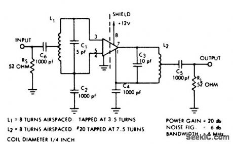
100 MHz RF amplifier using the ECG703A IC. Reverse AGO may be obtained at pin 5 (courtesy GTE Sylvania incorporated). (View)
View full Circuit Diagram | Comments | Reading(1104)
152_V_PENTODE_SERIES_TUBE_REGULATOR
Published:2009/7/20 7:11:00 Author:Jessie
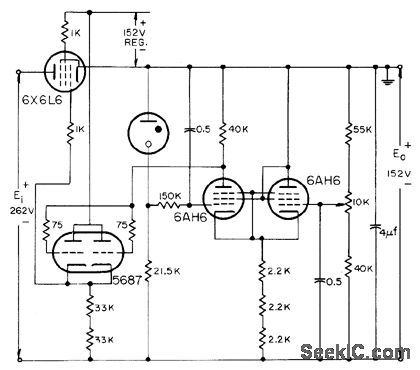
Has excellent frequency response, but this performance could also be obtained if cath. ode follower were amplifier using negative feedback for frequency compensation, dong with better regulation and lower d-c resislance.-NBS, Handbook Preferred Circuits Navy Aeronautical Electronic Equipment, Vol. 1, Electron Tube Circuits, 1963, p N2-11. (View)
View full Circuit Diagram | Comments | Reading(1183)
PREFERRED_250_V_D_C_REGULATOR
Published:2009/7/20 7:09:00 Author:Jessie
Provides either polarity of output with 1% regulation, from minimum of 300 v d-c. C5 is minimum of 4 mfd.-NBS, Handbook Preferred Circuits Navy Aeronautical Electronic Equipment, Vol. 1, Electron Tube Circuits, 1963, PC 7, p 7-2. (View)
View full Circuit Diagram | Comments | Reading(771)
107_MHz_to_45_MHz_convener_using_two_3N204_dual_gate_MOSFETs
Published:2009/7/20 7:08:00 Author:Jessie
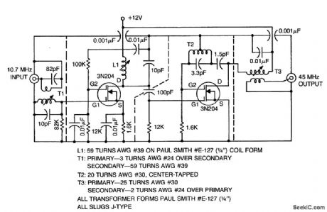
10.7 MHz to 45 MHz convener using two 3N204 dual-gate MOSFETs(courtesy Texas Instruments Incorporated). (View)
View full Circuit Diagram | Comments | Reading(861)
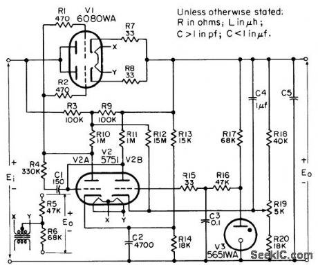
REMOTE___SENSING_6_V_REGULATOR
Published:2009/7/20 7:07:00 Author:Jessie
Used when small lead resistance between regulator and load is physically impossible. Voltage Eo' is essentially voltage that appears directly across load. Differential amplifier senses and corrects for changes in this volt-age rather thon for changes in Eo at regulator output terminals.-NBS, Handbook Preferred Circuits Navy Aeronautical Electronic Equipment, Vol. 11, Semiconductor Device Circuits, PSC 1, p 1-11. (View)
View full Circuit Diagram | Comments | Reading(838)
Double_balanced_mixer_with_broadband_inputs_and_9_MHz_tuned_output
Published:2009/7/20 7:07:00 Author:Jessie
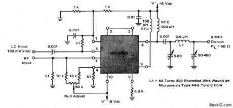
Double balanced mixer with broadband inputs and 9 MHz tuned output. The 3 dB bandwidth of the 9 MHz output tank is 450 kHz. Since the input is broadband the circuit can operate from HF to VHF. The local oscillator frequency should be +9 MHz (courtesy Motorola Semiconductor Products Inc.). (View)
View full Circuit Diagram | Comments | Reading(1086)
25_watt_UHF_amplifier_for_450_to_512_MHz
Published:2009/7/20 7:05:00 Author:Jessie
25-watt UHF amplifier for 450 to 512 MHz (courtesy Motorola Semiconductor Products Inc.). (View)
View full Circuit Diagram | Comments | Reading(1142)
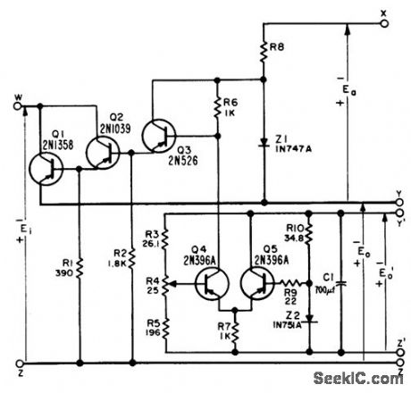
DARLINGTON_CONNECTED_SERIES_REGULA_TOR
Published:2009/7/20 7:04:00 Author:Jessie
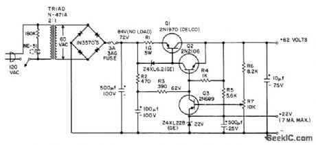
Designed for output currents up to 2 amp average or 3.5 amp peak. Output voltage can be adjusted from 45 to 65 v by R7. Ripple is less than 1 my rms at no load, increasing to 60 my peak-to-peak at 2 amp. Regulation is 2.1% at 2 amp and 0.72% at 1 amp.- Transistor Manual, Seventh Edition, General Electric Co., 1964, p 228. (View)
View full Circuit Diagram | Comments | Reading(805)
Product_detector_using_an_MC1596G
Published:2009/7/20 7:03:00 Author:Jessie
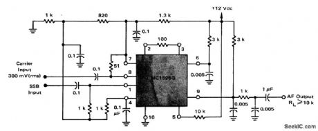
Product detector using an MC1596G. This circuit requires a single +12-volt supply. The circuit performs well with carrier level of 100 to 500 m VRMS. No transformers or tuned circuits are required for excellent performance from very low frequencies up to 100 MHz The audio output at pin 6 can be used to drive AGO (courtesy Motorola Semiconductor Products Inc.). (View)
View full Circuit Diagram | Comments | Reading(1086)
Amplitude_modulator_using_an_MC1596G
Published:2009/7/20 7:00:00 Author:Jessie
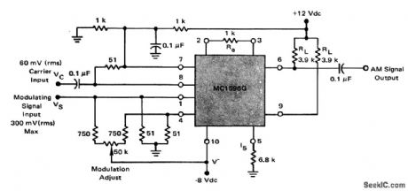
Amplitude modulator using an MC1596G. Modulation levels from zero to greater than 100% can be obtained with this circuit (courtesy Motorola Semiconductor Products Inc.). (View)
View full Circuit Diagram | Comments | Reading(1874)
PHASE_SHIFTING_ANTENNAFIER
Published:2009/7/20 6:59:00 Author:Jessie
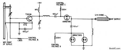
Control voltages A,B, and C together produce up to 180°phase shift with adequate matching, for beam-steering arrays. Ganged potentiometers with appropriately tapered windings can provide the control voltages and relate beam position to shaft rotation.-J. F. Rippin, Making the Antenna an Active Partner, Electronics, 38:16, p 93-96. (View)
View full Circuit Diagram | Comments | Reading(669)
30_MHz_RF_to_5_MHz_IF_mixer
Published:2009/7/20 6:59:00 Author:Jessie
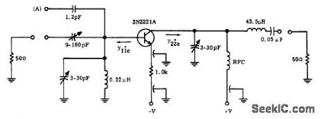
30 MHz RF to 5 MHz IF mixer. Injection point for the external local oscillator is at point A. The injection frequency is 35 MHz. The output of the 2N221A mixer is tuned to the difference of the two signals (courtesy Motorola Semiconductor Products Inc.). (View)
View full Circuit Diagram | Comments | Reading(1106)
| Pages:898/2234 At 20881882883884885886887888889890891892893894895896897898899900Under 20 |
Circuit Categories
power supply circuit
Amplifier Circuit
Basic Circuit
LED and Light Circuit
Sensor Circuit
Signal Processing
Electrical Equipment Circuit
Control Circuit
Remote Control Circuit
A/D-D/A Converter Circuit
Audio Circuit
Measuring and Test Circuit
Communication Circuit
Computer-Related Circuit
555 Circuit
Automotive Circuit
Repairing Circuit