
Index 203
static operating point adjustment circuit
Published:2011/6/11 1:50:00 Author:chopper | Keyword: static, operating point, adjustment circuit
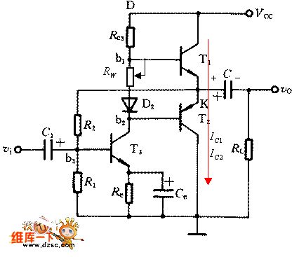
(1)adjustment at VC=0.5VCCUse voltmeter to measure the voltage of point K to ground and adjust R2 to make VK=0.5VCC.(2)adjustment of quiescent current IC1,IC2Minimize the resistance of RW first.when the power source is available,add sinusoidal signal to input end and use oscillograph to measure voltage waveform of load RL,and then,adjust RW until the moment that crossover distortion of output waveform disappears.
(View)
View full Circuit Diagram | Comments | Reading(715)
complementary symmetry principle circuit of power supply
Published:2011/6/11 5:13:00 Author:chopper | Keyword: complementary symmetry, principle, power supply
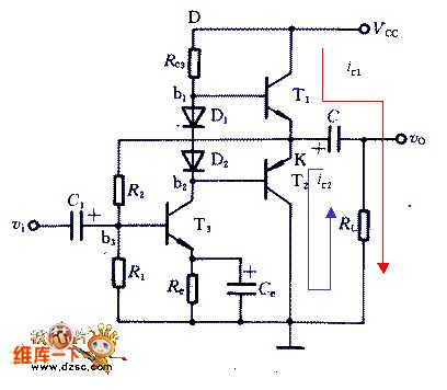
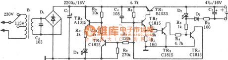
The picture 1 is a complementary symmetry principle of one power source circuit. T3 forms preamplifier stage,T1 and T2 form output stage of complementary symmetry circuit.Only the value of R1,R2 is necessary to make IC3,VB2 and V1 reach the required value when it is static.Provide T1 and T2 with a appropriate setover to make the electric potential VK=VCC/2.
(View)
View full Circuit Diagram | Comments | Reading(908)
LM393 nickel-cadmium battery charger circuit of high performance-price ratio
Published:2011/6/22 10:15:00 Author:chopper | Keyword: nickel-cadmium battery charger, high performance-price ratio
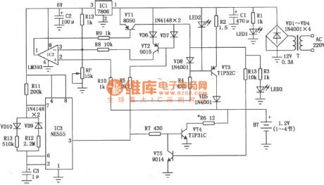
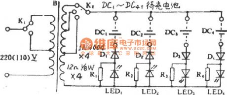
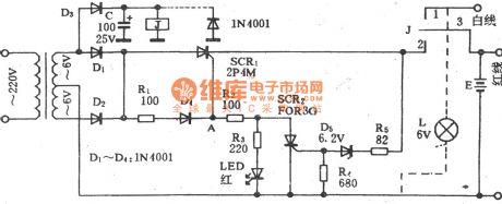
The LM393 nickel-cadmium battery charger circuit of high performance-price ratio is shown as the picture,it has the following features:(1)The process of constant-current charge runs with the process of heavy current discharge.The value of current of constant-current charge is about 300mA.And the discharge current increases along with the increase of battery voltage and the value of discharge current will reach 400mA when the battery is to the full value.The charging time is 1.5 second,discharging time is 0.5 second,and take turns. When the heavy current charge is over,there is about 5mA purling current charging.(2)The detection of battery voltage works during the discharging.It is because that the voltage of charge is greater than the discharge.
(View)
View full Circuit Diagram | Comments | Reading(3709)
MAX1757 lithium ion battery charger circuit
Published:2011/6/17 20:28:00 Author:chopper | Keyword: lithium ion, battery charger
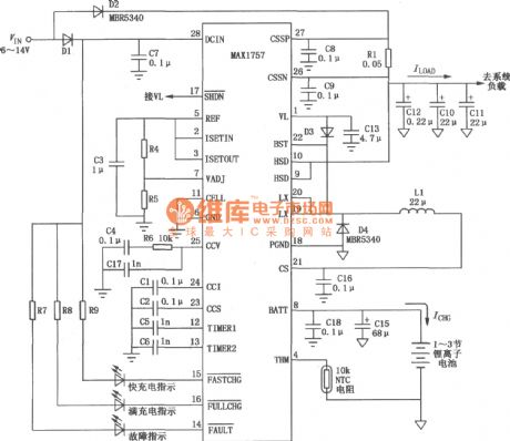
MAX1757 is formed by power supply and charger.As to power supply,there are DC/DC step-down convertor and 5.4V linear voltage regulator.DC/DC convertor can charge the battery with constant current and voltage,and its maximum charge current can reach 1.5A.The typical application circuit of MAX1757 is shown as follows.
(View)
View full Circuit Diagram | Comments | Reading(1962)
2.75W constant voltage/constant current general input charger power supply circuit
Published:2011/6/20 2:39:00 Author:TaoXi | Keyword: 2.75W, constant voltage, constant current, general input charger, power supply
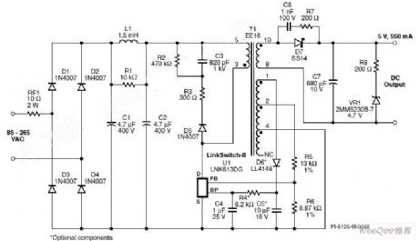
The 2.75W constant voltage/constant current general input charger power supply circuit is as shown in the figure, this design uses the Power Integrations's LinkSwitch series product LNK613DG. This design is very suitable for the cellphone or the USB charger applications such as the cell phone battery charger, the USB charger and the constant pressure/constant current applications.
In this design, the diodes D1-D4 rectify the AC input, the capacitance C1 and C2 filter the DC input. The π type filter is composed of the L1, C1 and C2 to attenuate the differential mode conduction EMI noises.
The RCD-R ground-clamp circuit is composed of the D5, R2, R3 and C3, it can be used to limit the drain voltage peak which is caused by the leakage inductance.
(View)
View full Circuit Diagram | Comments | Reading(914)
5W general input constant voltage/constant current charger power circuit
Published:2011/6/20 2:49:00 Author:TaoXi | Keyword: 5W, general input, constant voltage, constant current, charger, power circuit
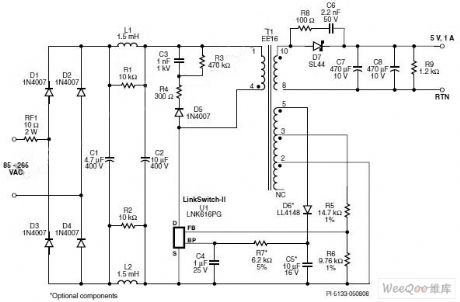
The 5W general input constant voltage/constant current charger power circuit is as shown in the figure, this design uses the Power Integrations's LinkSwitch-II series product LNK-616PG. This design is very suitable for the cellphone or the USB charger applications such as the cell phone battery charger, the USB charger and the constant pressure/constant current applications.
As the response of the voltage droping of the pin-FB, the switch frequency will reduce too, so as to realize the linear constant current output. The RCD-R ground-clamp circuit is composed of the D5, R3, R4 and C3, it can be used to limit the drain voltage peak which is caused by the leakage inductance. The resistor R4 has large value to avoid the drain voltage waveform oscillation which is caused by the leakage inductance, this can improve the voltage stability and reduce the EMI generation.
(View)
View full Circuit Diagram | Comments | Reading(665)
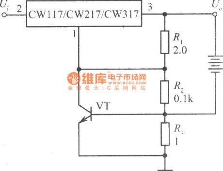
current-limiting protection charger of CW117/CW217/CW317 circuit
Published:2011/6/16 0:46:00 Author:chopper | Keyword: current-limiting protection, charger
View full Circuit Diagram | Comments | Reading(1042)
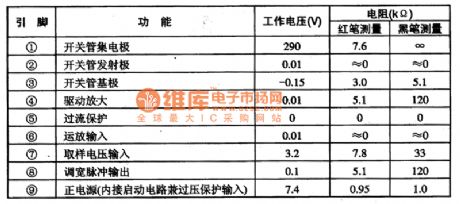
STR-S6708 switching power supply thick film integrated circuit
Published:2011/6/15 7:33:00 Author:chopper | Keyword: switching power supply, thick film
STRS6708 is a mixed type switching power supply thick film integrated circuit (View)
View full Circuit Diagram | Comments | Reading(1278)
the protection circuit of power circuit
Published:2011/6/11 21:10:00 Author:chopper | Keyword: protection circuit, power circuit
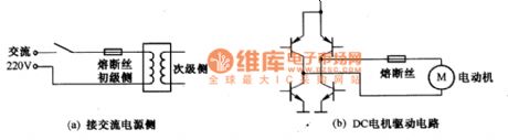
The current in power circuit is great and wecan adopts fuse,diode,transistor circuit to limit the current.Fuse is the simplest protection component.Picture a,b are the examples of setup method of fuse.The fuse is connected with the protection circuit and loads in series.Classify by fusing time,there are fast type,low type and normal type.We should select appropriate fuse based on the different loads and driving circuit.
(View)
View full Circuit Diagram | Comments | Reading(718)
STR-S5708 switching power supply thick film integrated circuit
Published:2011/6/15 7:34:00 Author:chopper | Keyword: switching power supply, thick film
STRS5708 is a mixed type switching power supply thick film integrated circuit (View)
View full Circuit Diagram | Comments | Reading(676)
printed plate of switch power supply design technique circuit
Published:2011/6/11 22:01:00 Author:chopper | Keyword: printed plate, switch power supply
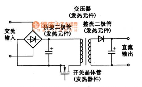
Switch power supply uses high speed switch to control high voltage and great current.If the speed of switch is not fast,the comsuption of transistor will increase and the temperature will ascend.When current changing rate di/dt is comparatively big,it will cause biggish noise voltage.When the inductance of line of printed plate is different,the switch waveform is different.The inductance of line is large,the surge of voltage waveform is large and the step gapof current waveform is large too.Therefor,the lines of switch current should be short and thick to decrease the inductance.
(View)
View full Circuit Diagram | Comments | Reading(781)
TWH9312 sealed lead-acid battery charger circuit
Published:2011/6/17 6:41:00 Author:chopper | Keyword: sealed, lead-acid battery, charger circuit
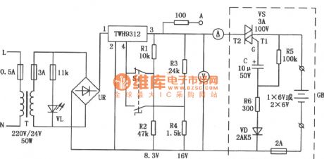
The charger circuit of sealed lead-acid battery is shown as follows.It can charge one or two batteries whose value are 6V or 4Ah for one time. The part of stable voltage adopts switch type stabilized voltage supply module TWH9312,and its scope of input voltage is wide.It also includes protection circuit of over-current,short circuit inside,and it is safe and reliable.
(View)
View full Circuit Diagram | Comments | Reading(3836)
CD4069 solar energy charger circuit
Published:2011/6/17 3:00:00 Author:chopper | Keyword: solar energy, charger circuit
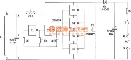
The solar energy charger circuit is as follows.It adopts integrated circuit CD4069(6 gate inverter,and can be replaced by 74HC04),field effect tube VT,diode VD,and some components like resistor and capacitor.The solar energy battery is set up at end A and B,and it is connected to end M,N by chargeable nickel-cadmium battery.
(View)
View full Circuit Diagram | Comments | Reading(2592)
12V DC electrical motor driving current circuit
Published:2011/6/20 3:56:00 Author:TaoXi | Keyword: 12V, DC, electrical motor, driving current
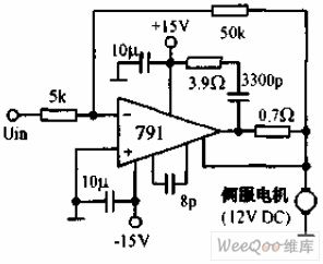
The 12V DC electrical motor driving current circuit uses the 791 power operational amplifier which is in the phase-reversing connection state, the voltage gain is 10, and it can be used to drive the positive and negative rotation No.8 12V DC servo motor. The power integrated op-amp needs to add the radiator.
(View)
View full Circuit Diagram | Comments | Reading(794)
degree of spoilage of food determinator circuit
Published:2011/6/14 3:18:00 Author:chopper | Keyword: degree of spoilage, food, determinator
View full Circuit Diagram | Comments | Reading(755)
Jinbao BC-60 multiple use charger circuit
Published:2011/6/14 3:19:00 Author:chopper | Keyword: Jinbao, multiple use, charger
View full Circuit Diagram | Comments | Reading(841)
Taiwan clairvoyance charger circuit
Published:2011/6/14 3:20:00 Author:chopper | Keyword: Taiwan, clairvoyance, charger
View full Circuit Diagram | Comments | Reading(989)
Aiwa AC-209H charger circuit
Published:2011/6/14 3:21:00 Author:chopper | Keyword: Aiwa, charger
View full Circuit Diagram | Comments | Reading(1235)
Furi F24 cassette mechanism switch power supply circuit
Published:2011/6/14 3:22:00 Author:chopper | Keyword: Furi, cassette mechanism, switch power supply
View full Circuit Diagram | Comments | Reading(900)
constant current battery charger of CW117/CW217/CW317 circuit
Published:2011/6/16 1:02:00 Author:chopper | Keyword: constant current, battery charger

We can produce many kinds of battery charger by using three-terminal adjustable output voltage integrated regulator.The following picture describes a constant current battery charger,This circuit is the same with constant current source.Because the resistance R is 24Ω,the output current Io=1.25/24=52mA,and charge the battery with the constant current 52mA.It can offer different charge current by changing the value of resistance R.
(View)
View full Circuit Diagram | Comments | Reading(936)
| Pages:203/291 At 20201202203204205206207208209210211212213214215216217218219220Under 20 |
Circuit Categories
power supply circuit
Amplifier Circuit
Basic Circuit
LED and Light Circuit
Sensor Circuit
Signal Processing
Electrical Equipment Circuit
Control Circuit
Remote Control Circuit
A/D-D/A Converter Circuit
Audio Circuit
Measuring and Test Circuit
Communication Circuit
Computer-Related Circuit
555 Circuit
Automotive Circuit
Repairing Circuit