
Index 218
AC Voltage Regulator Nine
Published:2011/5/22 1:29:00 Author:Michel | Keyword: AC Voltage Regulator, Nine
The AC voltage regulator introudced in the example is made from 100-200W mains transformer and discrete components with simple circuits and material which can be used by the area's famlies whose line voltage is low(190-220V).
Circuit's Work Principle
The AC voltage regulator is composed of power supply circuit,voltage test control circuit and it is showed as the picture 5-48.The power supply circuitconsists of mains switch,S,fuse,FU,transformer,T,diode,VD2,capacitor,C1-C3,power suorce indication LED,VL2,resistor,R2 and R8 and voltage regulation diode,VS.
(View)
View full Circuit Diagram | Comments | Reading(1353)
AC Voltage Regulator Eight
Published:2011/5/22 1:13:00 Author:Michel | Keyword: AC Voltage Regulator, Eight
The automatic AC voltage regulatorintroduced in the example owns broad voltage regulation range,which can output 220V alternating voltage when the input alternating voltage is 110-380V so it's availabe for where the alternating voltage power supply is unstable.
Circuit's Work Principle
This AC voltage regulator circuit is composed of power supply circuit,voltage test control circuit and voltage regulation output circuit and it is showed as the picture 5-47.The power supply circuit consists of reduction voltage capacitor,C2,current-limiting resistor,R31and R33,commutation diode,VD44 and VD45,filter capacitor,C3 and C4,potentiometer,RP and voltage regulation diode,VS1. (View)
View full Circuit Diagram | Comments | Reading(1813)
AC Voltage Regulator Seven
Published:2011/5/22 1:10:00 Author:Michel | Keyword: AC Voltage Regulator, Seven
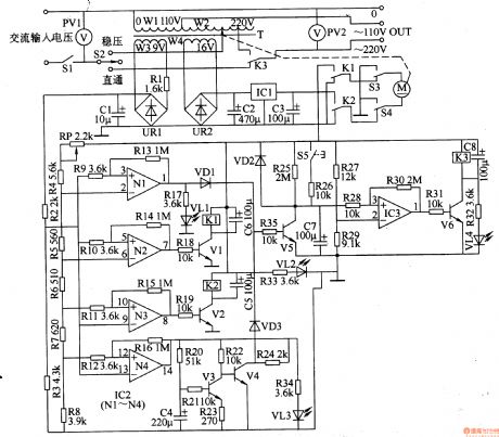
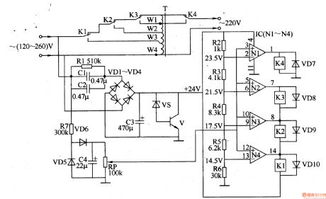
The AC voltage regulator introudced in the example has the functions of bootstrap power transmission delay,regulated output voltage,overvoltage and undertension's protection and indication and its output power is 3kW.
Circuit's Work PrincipleThe AC voltage regulator is composed of power supply circuit,lifting and reduction control circuit,bootstrap time delay circuit,overvoltage protection circuit and undertension protection circuit and it is showed as the picture 5-46.The power supply circuit consists of mains switch,S1, voltmeter,PV1,voltage-regulating transformer,T,rectifier bridge,UR2 and three-terminal voltage regulation IC,IC1,and filter capacitor,C1 and C2. (View)
View full Circuit Diagram | Comments | Reading(2574)
AC Voltage Regulator Six
Published:2011/5/22 1:08:00 Author:Michel | Keyword: AC Voltage Regulator, Six
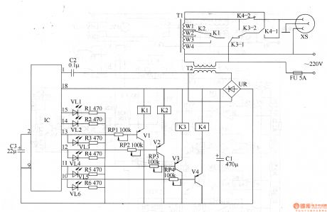
The voltage AC regulator introduced in the example is controlled by SL322 LED driver IC.It can be used as automatic tap changer and voltage lighting indication where the commercial power often is low.
Circuit's Work Principle
The voltage AC regulator is composed of power supply circuit,voltage test control circuit and control operation circuit and it is showed as the picture 5-45.The power supply circuit consists of fuse,FU ,mains transformer,T,rectifier bridge,UR and filter capacitor,C1. (View)
View full Circuit Diagram | Comments | Reading(2672)
AC Voltage Regulator Five
Published:2011/6/3 5:02:00 Author:Michel | Keyword: AC Voltage Regulator, Five
The input and output voltage of the lifting voltage AC regulator introduced in the example are 150-230V and 220 (1土5%)V respectively.This regulator can be used by these families with unstabilized and low voltage.
Circuit's Work Principle
This AC regulator circuit is composed of power supply circuit,voltage test circuit and lifting voltage control circuit and it is showed as the picture 5-44.The power
supply circuit consists of mains switch,S,fuse,FU,mains transformer,T,commutation diode,VD1-VD4,filter,capacitor,C1 and C2 and three-termianl voltage control IC,IC. (View)
View full Circuit Diagram | Comments | Reading(2352)
AC Voltage Regulator Four
Published:2011/5/22 1:02:00 Author:Michel | Keyword: AC Voltage Regulator, Four
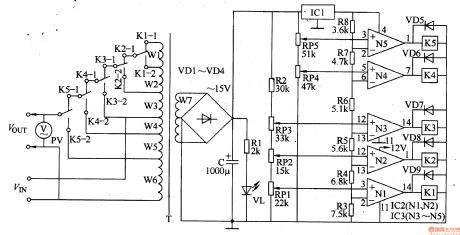
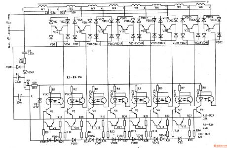
The input and output voltage range and output power range AC voltage regulator introudced in the example are 160-270V,220(1士5%)V and 600-800W respectively,which can meet the need of general household appliances.
Circuit's Work Principle
The AC voltage regulator circuit is composed of lifting and reduction voltage commutation circuits and automatic control circuit and it is showed as the picture 5-43.The lifting and reduction commutation circuits consists of power supply transformer's(T) Wl-W6 winding,relay's normally closed contact Kl-l-K5-1,normally open contact Kl-2-K5-2 and voltmeter,PV and it is showed as the picture. (View)
View full Circuit Diagram | Comments | Reading(4560)
AC Voltage Regulator Three
Published:2011/5/22 1:00:00 Author:Michel | Keyword: AC Voltage Regulator, Three
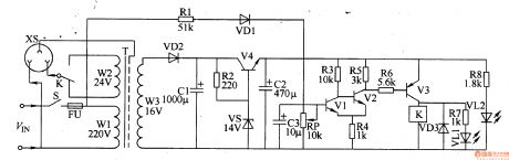
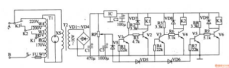
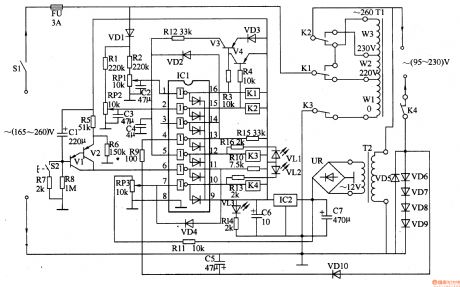
The AC voltage regulator introudced in the example has the functions of automatic voltage control and regulation.Its input voltage is from 120V to 260V,output voltage is 220V(11士10%)V and output power is from 300 to 1000W(It depends on transformer and relay contact terminal's current capacity).
Circuit's Work Principle
The AC voltage regulator circuit is composed of power supply circuit and voltage test circuit and it is showed as the picture 5-42.The power supply circuit consists of reduction voltage capacitor,C1 and C2,resistor,R1,commutation diode,VD1-VD4,filter capacitor,C3,voltage control diode,VS and transistor,transistor,V. (View)
View full Circuit Diagram | Comments | Reading(8664)
Switch D. C. Regulated Power Supply Three
Published:2011/6/3 5:00:00 Author:Michel | Keyword: Switch, D. C., Regulated Power Supply, Three
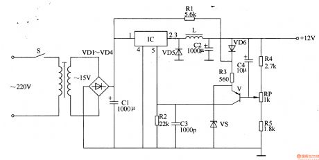

The switch D. C. regulated power supply circuit introduced in the example uses TWH8778 electronic switching IC and it has high work's efficiency,its circuit is simple which is easy to manufature.The output voltage and current of the power supply circuit are +12V and 1A respectively.
Work's Principle of the CircuitThe switch D. C. regulated power supply circuit is composed of input converting circuit,switch output circuit and automatical voltage regulator circuit and it is showed as the picture 5-39.
The input converting circuit consists of mains switch S,mains transformer T,commutation diode VD1-VD4 and filter capacitor C1.The switch output circuit is composed of electronic switching intergrated circuit,IC,resistor R1,R2, diode,VD5,induction coil,L and capacitor C2,C3. (View)
View full Circuit Diagram | Comments | Reading(1217)
AC Voltage Regulator Two
Published:2011/5/22 0:57:00 Author:Michel | Keyword: AC Voltage Regulator, Two
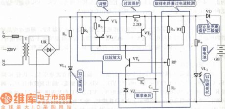
The AC voltage regulator introudced in the example can control and regulate voltage automatically,cut off when it is idle load and voltage is over to save engery and protect the regulator.The regulator's input voltage range is from 65V to 250V,output voltage range is 195V to 230V and output power is 500W.
Circuit's Work Principle
The AC voltage regulator circuit is composed of power supply voltage control,voltage test,control circuit and time delay circuit and it is showed as the picture 5-41.The power supply voltage control consists of mains transformer,T,rectifier bridge,UR,filter capacitor,C6 and C7,three-terminal voltage control IC,IC2 and power indication LED,VL3 and current-limiting resistor,R14.
(View)
View full Circuit Diagram | Comments | Reading(4729)
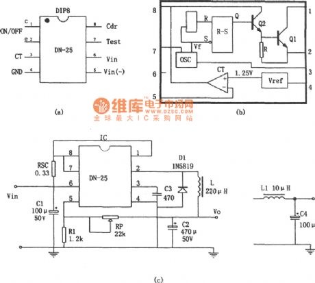
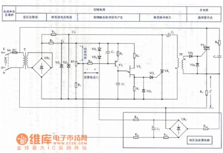
DN-25 integrated circuit switching voltage-stabilized power supply circuit
Published:2011/5/19 19:32:00 Author:Christina | Keyword: switching, voltage-stabilized, power supply circuit
After startup, the oscillator starts working, the output VF signal is reshaped and transformed by R-S trigger to produce a original frequency rectangular pulse excitation voltage, and the VF signal is amplified by the darlington circuit which is composed of th Q1 and Q2 then output by pin-2. You can adjust the output voltage V0 by adjusting the voltage of comparator reversed-phase input terminal pin-5. By changing pin-5's voltage, we can adjust R-S trigger excitation pulse width, and cause the changing of the output voltage Vo. This voltage-stabilized power supply VIN=25V,Vo=(1+RP/XVREF), the stability is 0.12%; the load regulation is 0.03%; the short-circuit limit current is IOSH=1.1A; the efficiency is η=82.50%; the ripple wave is less than 120mVp-p.
(View)
View full Circuit Diagram | Comments | Reading(945)
Manostat power supply composed of the L296 large current switching power supply chip
Published:2011/5/19 18:48:00 Author:Christina | Keyword: Manostat power supply, large current, switching power supply chip
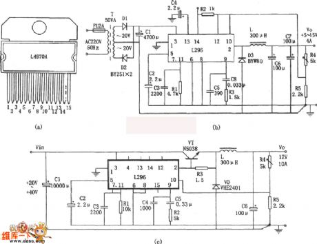
The Manostat power supply which is composed of the L296 large current switching power supply chip is as shown. a, b and c are the 5~15V, 4A manostat power supply which is composed of the L296 monolithic large current switching power supply chip. Features of the L296 monolithic large current switching power supply chip are: (1)Perfect protecting function. (2)The maximum output current is 4A, power is 160W, the output voltage is between 5.1~40V. (3)With special functions such as the working prohibition control, the synchronous control, the reset circuit and the stich over-voltage protection circuit. The figure c shows the form of current expansion circuit.
(View)
View full Circuit Diagram | Comments | Reading(5139)
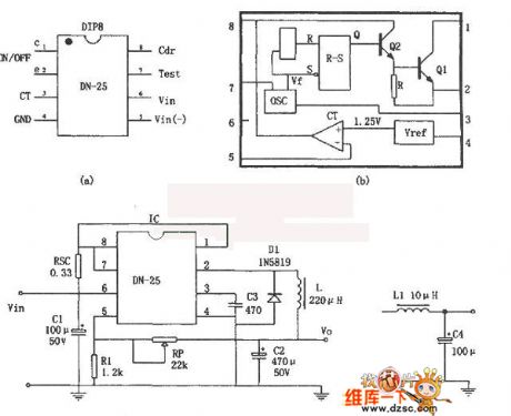
The switch steady power supply circuit consisting of DN-25 single chip switch regulator
Published:2011/6/5 2:28:00 Author:Seven | Keyword: power supply, single chip
This is a switch steady power supply consisting of DN-24 integrated circuits. DN-25 is a power supply element of the single chip steady regulator, which is suitable for making the steady power supply of intermediate current and wide voltage range. Its main function parameters are as follows: input voltage is VIN=3~40V, output voltage is Vo=1.25~24V(can be continuously adjusted), maximum output current IOM=1A, maximum output power POM=36W, loading short limiting current IOSH≤1.1A. DN-25 is in 8-pin dual in-line package(DIP-8), whose internal circuit includes:(1) oscillator(OSC); (2)R-S trigger; (3) output switch.
(View)
View full Circuit Diagram | Comments | Reading(958)
The simplest lithium battery charger circuit
Published:2011/6/3 20:03:00 Author:chopper | Keyword: lithium battery charger
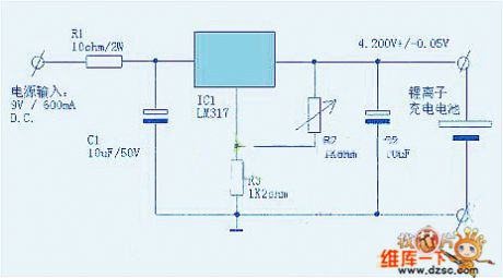
View full Circuit Diagram | Comments | Reading(1423)
The DC low-voltage switch circuit designed with NE555
Published:2011/6/5 21:19:00 Author:Seven | Keyword: low-voltage switch circuit
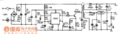
VD1-VD4,R1,C1 and C2 of the switch form a rectifier filter circuit. NE555,R2,R3,C4,VD6 and so on form a multi-resonate oscillating circuit, whose frequency is about 20KHz. R4, C3 and VD5 form a step-down steady circuit, which provide the NE555 with a working voltage of 12V. The high power pipe VT1 and the transformer T consist a switch circuit. The working condition of VT1 is controlled by 3-pin of NE555, the conducting time depends on the width of pulses, the pulse width is adjusted by R3. If the pulse width becomes wider, the output voltage is getting higher, and vice versa.
(View)
View full Circuit Diagram | Comments | Reading(1180)
The voltage stabilizing DC power supply circuit of 5V, 4W switch
Published:2011/6/2 6:58:00 Author:Seven | Keyword: DC power supply
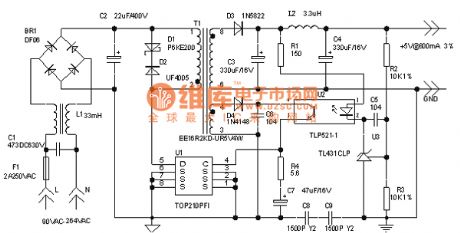
View full Circuit Diagram | Comments | Reading(827)
The siren control keyboard circuit
Published:2011/6/2 6:54:00 Author:Seven | Keyword: keyboard circuit
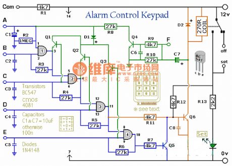
View full Circuit Diagram | Comments | Reading(755)
The over-current/pressure/heat charging circuit
Published:2011/6/2 6:53:00 Author:Seven | Keyword: over-current/pressure/heat, charging circuit
View full Circuit Diagram | Comments | Reading(670)
The AC voltage regulation circuit with stabilization sectors
Published:2011/6/2 6:38:00 Author:Seven | Keyword: voltage regulation, stabilization sectors
View full Circuit Diagram | Comments | Reading(790)
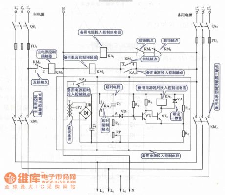
The automatic switching circuit of the dual-way 3-phase power supply
Published:2011/6/2 3:11:00 Author:Seven | Keyword: automatic switching circuit, power supply
View full Circuit Diagram | Comments | Reading(1786)
15W Triple Output DC / DC module power supply design circuit
Published:2011/5/24 0:05:00 Author:John | Keyword: DC / DC module power supply
DC / DC module has been widely used in railway communications, microwave communications, industrial control, marine electronics, avionics, ground radar, fire-fighting equipment and medical equipment, teaching equipment and many other fields. Many applications require multi-output, such as SCM intelligent controller. SCM needs power supply of 5V, while the op-amp usually needs power supply of 12V. During the design of multiple outputs, there are many different points from the single output. It is necessary to consider transformer pin constraints, multi-secondary transformer design and voltage regulator circuit achievement. It is also needed to consider the load rates for light load and full load of each channel and the characteristics for cross-load regulation.
(View)
View full Circuit Diagram | Comments | Reading(2498)
| Pages:218/291 At 20201202203204205206207208209210211212213214215216217218219220Under 20 |
Circuit Categories
power supply circuit
Amplifier Circuit
Basic Circuit
LED and Light Circuit
Sensor Circuit
Signal Processing
Electrical Equipment Circuit
Control Circuit
Remote Control Circuit
A/D-D/A Converter Circuit
Audio Circuit
Measuring and Test Circuit
Communication Circuit
Computer-Related Circuit
555 Circuit
Automotive Circuit
Repairing Circuit