
Index 219
Practical constant current charger circuit
Published:2011/5/24 3:26:00 Author:John | Keyword: constant current charger
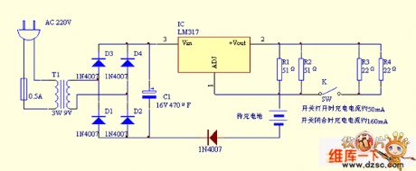
This circuit is actually a constant current source. Nuclear device is an integrated three-terminal adjustable regulator LM317T. Within the sufficient power supply voltage, LM317T can maintain a 1. 25V higher voltage of the + Vout than that of the ADJ. See the connection in the figure. The terminal end of ADJ is connected directly to rechargeable batteries. However, the internal resistance for ADJ terminal end is large (the current does not exceed 50μA under normal circumstances), so the circuit can be approximately regarded as an open circuit. But it can sample out of the voltage. If LM317T improves the voltage on the + Vout terminal end to be higher than that of ADJ terminal end of about 1.25V, the resistor cross-connected to the + Vout and ADJ can have the current of 1.25V/25.5Ω = 0. 05A = 50mA. (25.5Ω is the total resistance for the situation when R1 and R2 are parallel placed with the opening switch). Such current flows through the battery to charge the battery within a constant current.
(View)
View full Circuit Diagram | Comments | Reading(2583)
electric bicycle quick charger circuit
Published:2011/5/25 20:08:00 Author:John | Keyword: electric bicycle, quick charger
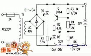
The AC220V electricity is stepped-down through transformer T1 and is regulated through the full-wave rectifier D1-D4. Thus the charging circuit is supplied to work. Then the output end is correctly accessed to the set recharged bottle. If each half-wave peak value of the rectifier output ripple voltage is higher than the output voltage of the battery, the thyristor SCR is triggered to conduct by the Q collector current. The current charges the battery through the SCR. When the pulsating voltage is close to battery voltage, the SCR is off and charging process stops. Conduction voltage for transistor Q can be adjusted by the regulation of R4. The R4 is generally adjusted, from large value to small value, to trigger SCR. LED D5 in the figure is used for the power indicator and D6 is used for charging instructions. (View)
View full Circuit Diagram | Comments | Reading(2096)
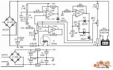
back-up power supply automatic charger circuit
Published:2011/5/25 20:06:00 Author:John | Keyword: automatic charger
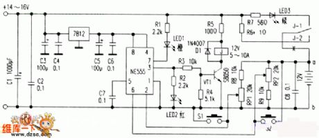
Backup power supply is temporary power supply equipment which is set in case of power failure or other reasons. Common ones are small back-up power generators and a variety of batteries. Among them, an economic and durable lead-acid storage battery is the first choice for back-up power supply. The authors have considered carefully designing an automatic battery charger for lead-acid batteries. The circuit is as shown in the figure (emitting the part that electricity is being bucked and rectified)
The core part of the circuit is composed by NE555 hysteresis comparator . R8, R9, RP1 and RP2 constitute sampling circuit and LED1-LED3 is an indicator for charging status. The charger of the battery is connected with an electrical relay, leading the cutting-off to be more reliable. S1 and S2 are touch switched, which are used to manually control the charging process. As a result, the circuit becomes more flexible and more convenient. (View)
View full Circuit Diagram | Comments | Reading(2968)
Energy-efficient motorcycle regulating rectifier circuit
Published:2011/5/23 21:30:00 Author:John | Keyword: motorcycle regulating rectifier
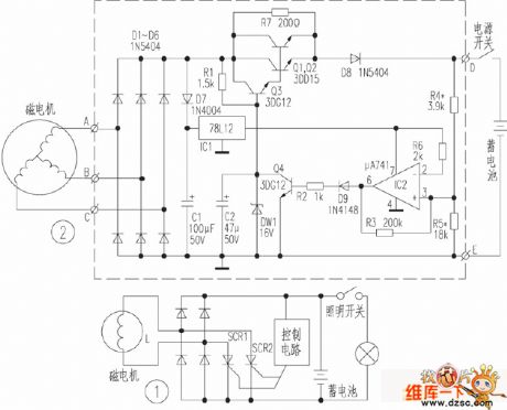
Motorcycles are generally powered by magneto of the car. Output voltage of Magneto is regulated by regulating rectifier to supply electric appliances on the car and to charge the battery. At present, parallel switching regulating rectifier are widely used in many domestic motorcycles, just shown in Figure 1. The device takes effects when the output voltage of magneto is over the rated voltage. The device takes effects when the output voltage of magneto is over the rated voltage. The thyristor rectifier SCR1 and SCR2 inside of SCR rectifier voltage regulator opens to clip the output voltage of magneto, achieving the voltage regulation.
(View)
View full Circuit Diagram | Comments | Reading(5015)
Pulse current limiting battery charger circuit
Published:2011/6/4 12:10:00 Author:John | Keyword: battery charger
Pulse current limiting battery charger circuit is shown below.
(View)
View full Circuit Diagram | Comments | Reading(6404)
Yilaida electric bicycle battery charger circuit
Published:2011/6/4 11:36:00 Author:John | Keyword: electric bicycle, battery charger
Yilaida electric bicycle battery charger circuit is shown below.
(View)
View full Circuit Diagram | Comments | Reading(6962)
Lamp inrush current suppression circuit
Published:2011/6/4 12:23:00 Author:John
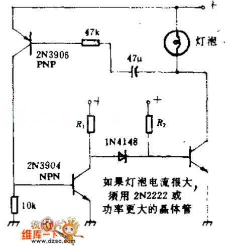
Inrush current is the main reason for failure of the lamp. The circuit can be used to limit such current. But when the filament reaches normal operating temperature, it can provide the lamp with a normal current. This circuit also applies to low pressure pilot lights. But as long as the voltage and current is no more than certain ratings of the transistor, any kind of light bulb can be used.
(View)
View full Circuit Diagram | Comments | Reading(926)
cotton machine controlling photoelectric control circuit
Published:2011/6/4 4:14:00 Author:John | Keyword: cotton machine
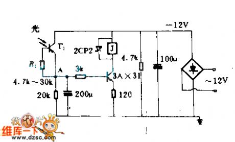
When the phototransistor T1 is illuminated, low resistance shows. At this time, the electric potential of point A drops and 3AX31 conducts. The relay sucks to control the cotton machine.
Capacitor of 200μF and resistor of 3 KΩ form the charging circuit, ensuring that electric potential of point A would not increase rapidly in the absence of light. The circuit plays the role of delaying and avoids the relay working too often. Resistor of 120Ω is the current feedback resistor, aiming to stabilize the operating point of 3AX31. 2CP2 is used to protect 3AX31.
(View)
View full Circuit Diagram | Comments | Reading(715)
SVGA color display DELL VI-1428 power supply circuit
Published:2011/6/4 7:45:00 Author:John | Keyword: color display
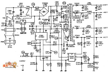
SVGA color display DELL VI-1428 power supply circuit is shown below.
(View)
View full Circuit Diagram | Comments | Reading(2931)
PARCO LFVDX-1448 type display power supply circuit
Published:2011/6/4 7:57:00 Author:John | Keyword: display
PARCO LFVDX-1448 type display power supply circuit is shown below.
(View)
View full Circuit Diagram | Comments | Reading(596)
Coupled with photoelectric isolation AC load control circuit
Published:2011/6/4 8:33:00 Author:John | Keyword: AC
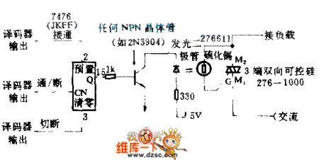
Microprocessor’s decoder output feedback to trigger 7476JK. And the trigger JK goes to trigger triac through the optocoupler. Therefore, the on / off control of a lamp or other AC load can be achieved. The optocoupler formed by an LED and a CdS photocell is placed within the hood. When the light emitted by LED shines on the photocell, the photocell's resistance decreases. So it will have a control voltage with proper size and direction to trigger the control pole of SCR. The SCR is conducted.
(View)
View full Circuit Diagram | Comments | Reading(601)
Textile machine with three-stop digital control device sensitive control circuit
Published:2011/6/4 3:54:00 Author:John | Keyword: Textile machine, digital control device
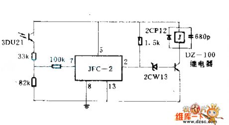
While any of many root warps breaks, light barrier attached with the root warp fells down. At this time, the light barrier blocks the light source of photodiode 3DU21. The relay in the line circuit releases. And the controlled motor stops. (View)
View full Circuit Diagram | Comments | Reading(843)
Electricity off and under-voltage automatical indicator protection circuit
Published:2011/6/4 12:51:00 Author:John | Keyword: automatical indicator
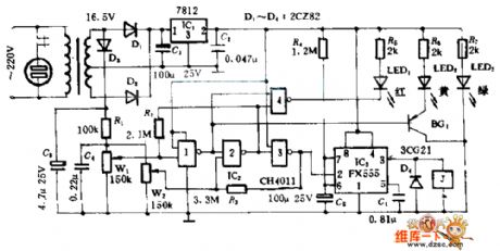
In this circuit, when the electricity is over the set upper limiting value of W1, LED2 lights. Door 2 locks to output 1 . J sucks and normally closed contacts break. Therefore, power failure protection can be temporarily achieved. When the electricity is under the set lower limiting value of W2, door 4 opens and LED1 lights. And door 3 outputs 0 so that J pulls. Power conservation can be again achieved. (View)
View full Circuit Diagram | Comments | Reading(663)
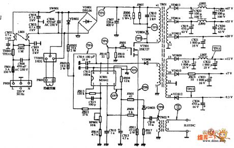
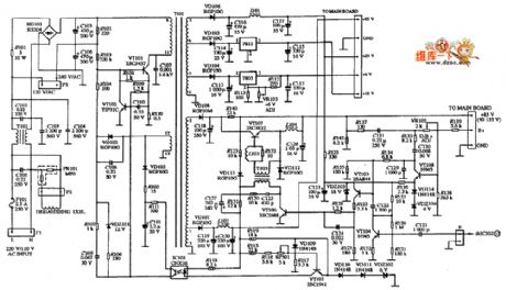
color monitor EMC EM-1428 type power supply circuit
Published:2011/6/9 4:35:00 Author:John | Keyword: color monitor
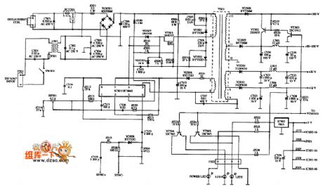
Color monitor EMC EM-1428 type power supply circuit is shown below.
(View)
View full Circuit Diagram | Comments | Reading(955)
SVGA color monitor ENVISION EC-1469 type power supply circuit
Published:2011/6/9 4:33:00 Author:John | Keyword: color monitor
SVGA color monitor ENVISION EC-1469 type power supply circuit is shown below.
(View)
View full Circuit Diagram | Comments | Reading(599)
Auto-grain machine optical axis circuit
Published:2011/6/5 4:12:00 Author:John | Keyword: Auto-grain machine
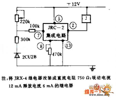
Firstly, use mechanical ventilation to send the grain to food stored grain box at certain height through the pipeline. Then the grain would flow grain stored pipeline with controlled door to automatic platform meter. When the grain flows to a certain weight, automatic platform meter would deliver a signal. The implementation components work to shut off the food pipe valve. At this time, automatic weighing process ends.
In the figure, the photodiode 2CU2B is installed on the automatic platform meter to receive the signal outputs during the weighing process. Such signal depends on whether the status of meter’s shaft has covered signals from optical signal light source or not. Optical signals received by photodiode would be amplified through the line to control the relay. Then the implementation components are controlled to realize the purpose to automatically transfer grain. (View)
View full Circuit Diagram | Comments | Reading(607)
ENVISION EC-1439 type display power supply circuit
Published:2011/6/5 10:00:00 Author:John | Keyword: display
ENVISION EC-1439 type display power supply circuit is shown in the following.
(View)
View full Circuit Diagram | Comments | Reading(728)
photosensitive II of SCR variable frequency synchronous starter circuit
Published:2011/6/7 0:16:00 Author:John | Keyword: variable frequency synchronous starter
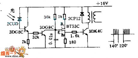
2CUD is used for photoelectric control. When it is affected by illumination, the photocurrent occurs to conduct 3DG8C. 3V voltage drop is generated on resistor with resistance of 2KΩ. Therefore, the next individual DG8C is also conducted (saturated). Both ends of 0.01μF capacitor is regarded as short-circuit. And double base tube BT33C stops oscillation and there is no output of line terminal.
Where there is no light, the two 3DG8C close. The double-base diode oscillator works, resulting in sharp pulse output waveform. Such would be amplified by 3DK4C to output trigger pulse waveform of the terminal, just as shown in the figure. Partial electrical angle with a pulse output is 140 ° and partial electrical angle with no pulse output is 220 °. This trigger pulse waveform is sent to the SCR inverter.
(View)
View full Circuit Diagram | Comments | Reading(603)
CZX-14-type display power supply circuit
Published:2011/6/9 4:57:00 Author:John | Keyword: display
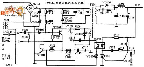
CZX-14-type display power supply circuit is shown below.
(View)
View full Circuit Diagram | Comments | Reading(517)
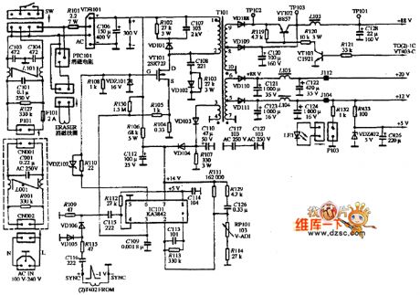
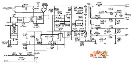
VGA multi-frequency color monitor CTX-C1435 type power supply circuit
Published:2011/6/9 4:53:00 Author:John | Keyword: multi-frequency color monitor
VGA multi-frequency color monitor CTX-C1435 type power supply circuit is shown below.
(View)
View full Circuit Diagram | Comments | Reading(716)
| Pages:219/291 At 20201202203204205206207208209210211212213214215216217218219220Under 20 |
Circuit Categories
power supply circuit
Amplifier Circuit
Basic Circuit
LED and Light Circuit
Sensor Circuit
Signal Processing
Electrical Equipment Circuit
Control Circuit
Remote Control Circuit
A/D-D/A Converter Circuit
Audio Circuit
Measuring and Test Circuit
Communication Circuit
Computer-Related Circuit
555 Circuit
Automotive Circuit
Repairing Circuit