
Index 204
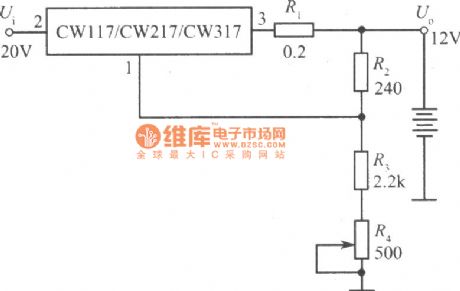
12V constant voltage charger of CW117/CW217/CW317 circuit
Published:2011/6/16 0:45:00 Author:chopper | Keyword: 12V, constant voltage, charger
View full Circuit Diagram | Comments | Reading(881)
STRZ4302 switch power supply thick film integrated circuit
Published:2011/6/14 9:28:00 Author:chopper | Keyword: switch power supply, thick film, integrated circuit
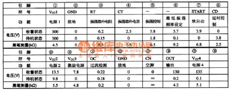
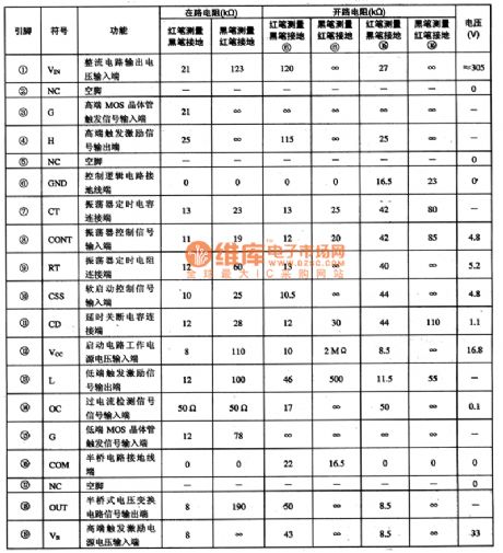
STRZ4302 is a switch power supply thick film integrated circuit produced by Company Samco,and it is applied to Changhong NEC cassette mechanism,such as G2967,PF29488,G2898 large-screen colour TV.1.function characteristicsSTRZ4302 integrated circuit includes oscillation circuit,soft start circuit,timing control circuit,pulse driving circuit,over-current protection circuit,driving circuit,and other miscellaneous function circuit.2.function and data of pinsSTRZ4302 adopts 15 pins package,and its function and data of pins of the integrated circuit are shown as the chart 1.
(View)
View full Circuit Diagram | Comments | Reading(1030)
STR-Z4267 switch power supply thick film integrated circuit
Published:2011/6/15 7:55:00 Author:chopper | Keyword: switch power supply, thick film, integrated circuit
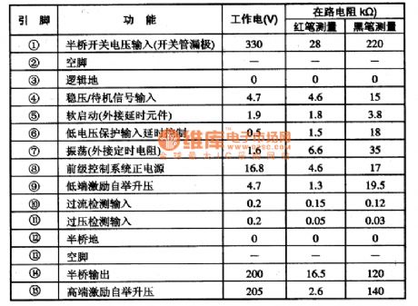
STRZ4267 is a switch power supply thick film integrated circuit produced by J (View)
View full Circuit Diagram | Comments | Reading(1600)
STR-Z3302 power supply thick film integrated circuit
Published:2011/6/15 7:54:00 Author:chopper | Keyword: power supply, thick film, integrated circuit
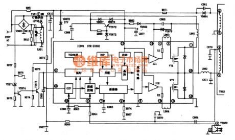
STRZ3302 is a voltage change power supply thick film integrated circuit of se (View)
View full Circuit Diagram | Comments | Reading(1476)
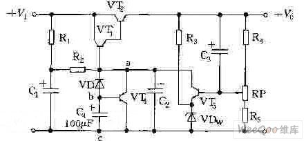
Large current adjustable voltage stabilization power supply circuit
Published:2011/6/22 1:48:00 Author:TaoXi | Keyword: Large current, adjustable, voltage stabilization, power supply
Circuit and working principle
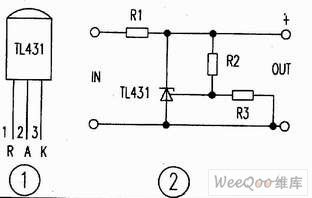
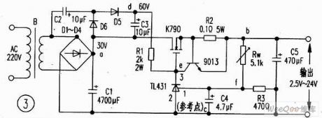
The pin figure of the TL413 is as shown in figure 1, the typical application of the TL413 is as shown in figure 2, the output voltage of pin-2 and pin-3 are V=2.5(R2十R3)V/R3. If we change the resistance value of R2, we can change the output reference voltage. Figure 3 shows the output current (about 6A) that is composed of the voltage reference and the regulator (the TL413 drives the external FET K790), this circuit is simple and safe.
The voltage regulation process: when the output voltage reduces, the electric potential of point f reduces, this potential is amplified by the T1431 to increase the voltage of point e, and it is adjusted by the K790, the electric potential of point b rises; on the contrary, when the output voltage rises, the electric potential of point f rises too, the electric potential of point e reduces, and it is adjusted by the K790, the electric potential of point b reduces.
(View)
View full Circuit Diagram | Comments | Reading(2517)
Switch power supply start-up circuit with the MOSFET
Published:2011/6/22 1:51:00 Author:TaoXi | Keyword: Switch, power supply, start-up, MOSFET
Switch power supply start-up circuit with the MOSFET (View)
View full Circuit Diagram | Comments | Reading(2238)
Switch power supply start-up circuit with the transistor
Published:2011/6/22 1:52:00 Author:TaoXi | Keyword: Switch, power supply, start-up, transistor
The Switch power supply start-up circuit with the transistor is as shown in the figure:
(View)
View full Circuit Diagram | Comments | Reading(1161)
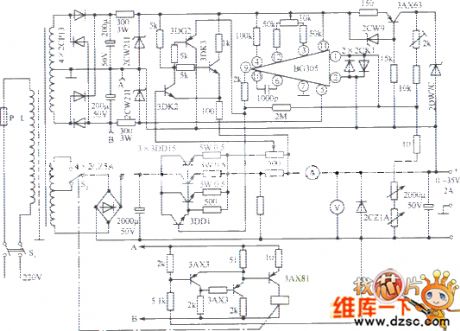
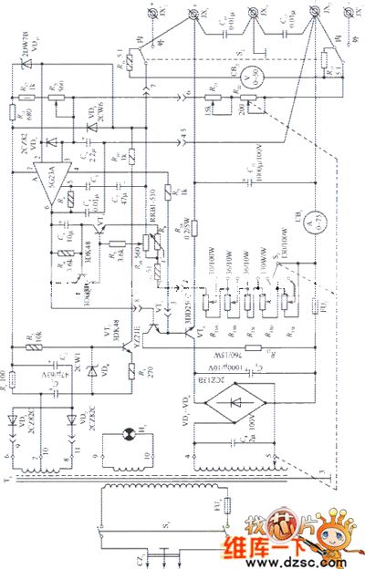
Three-phase no inverter UPS circuit charged by the two groups of battery and single pipe half-wave rectifier
Published:2011/6/22 1:55:00 Author:TaoXi | Keyword: Three-phase, no inverter, UPS, two groups, battery, single pipe, half-wave, rectifier
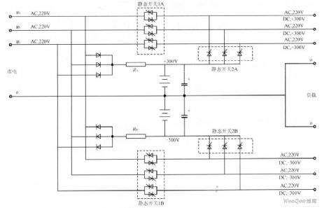
The Three-phase no inverter UPS circuit which ischarged by the two groups of battery and single pipe half-wave rectifier is as shown in the figure:
(View)
View full Circuit Diagram | Comments | Reading(4861)
Single-phase no inverter UPS circuit charged by the two groups of battery and single pipe half-wave rectifier
Published:2011/6/22 1:57:00 Author:TaoXi | Keyword: Single-phase, no inverter, UPS, two groups, battery, single pipe, half-wave, rectifier
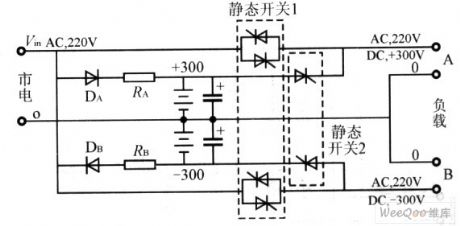
The Single-phase no inverter UPS circuit which ischarged by the two groups of battery and single pipe half-wave rectifier is as shown in the figure:
(View)
View full Circuit Diagram | Comments | Reading(1171)
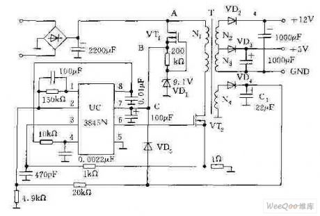
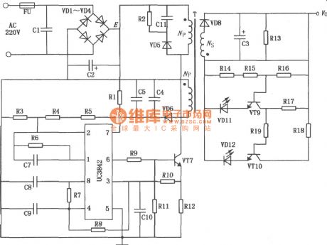
UC3842 battery charger of lectromotive bicycle circuit
Published:2011/6/22 9:54:00 Author:chopper | Keyword: battery charger, lectromotive bicycle
View full Circuit Diagram | Comments | Reading(9752)
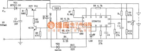
STD9732 simple charger circuit
Published:2011/6/17 20:39:00 Author:chopper | Keyword: simple, charger circuit
View full Circuit Diagram | Comments | Reading(988)
CD060 nickel-cadmium battery charger circuit of timing function
Published:2011/6/17 6:51:00 Author:chopper | Keyword: nickel-cadmium battery, charger circuit, timing
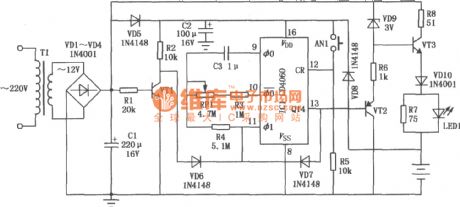
This circuit is a timing charger,the charging time can be adjusted between 5h and 25h.If the power supply is cut during charging,this circuit can accumulate the total time.This circuit can charge the number 5 nickel cadmium battery. (View)
View full Circuit Diagram | Comments | Reading(1263)
Low voltage band gap reference circuit
Published:2011/6/23 2:48:00 Author:TaoXi | Keyword: Low voltage, band gap, reference circuit
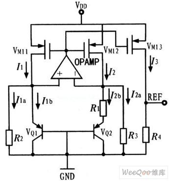
In order to meet the low voltage application of the band gap reference circuit, we use the current mode structure low voltage band gap reference circuit which is as shown in the figure. This circuit can output the voltage that is lower than 1V, this effectively reduces the power supply voltage of the circuit, at the same time this circuit uses the two-stage op amp with the negative feedback network and the Bias which has no relationship with the voltage to reduce the power sensitivity of the circuit.
(View)
View full Circuit Diagram | Comments | Reading(2729)
The 0~35V regulated power supply circuit
Published:2011/6/25 5:29:00 Author:Borg | Keyword: regulated power supply
View full Circuit Diagram | Comments | Reading(718)
The TDA7294 audio amplifier circuit
Published:2011/6/26 5:22:00 Author:Borg | Keyword: audio amplifier
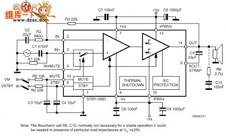
The TDA7294 audio amplifier circuit is shown as above.
(View)
View full Circuit Diagram | Comments | Reading(1943)
The 0~50V regulated power supply circuit
Published:2011/6/26 5:32:00 Author:Borg | Keyword: regulated, power supply
View full Circuit Diagram | Comments | Reading(1370)
The amplifier circuit of audio control and soft switch
Published:2011/6/27 19:32:00 Author:Borg | Keyword: amplifier circuit, audio control, soft switch
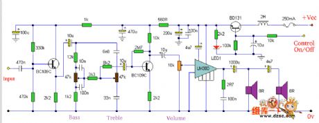
Soft switch is the configuration of the emitting pole follower that adopts the BD131 transistor as the switch. Collection is the wiring permanent power supply voltage, the conductor of the second half year series can only remove the noise of the power supply. Therefore, the conductor is not very important, which can be omitted, if the DC power supply is smooth enough. The control power supply is used in BD131 base harbour, the 10u capacitor and the 10K resistor have double functions: 1. One of them is responsible to that the 10u capacitor makes sure the switch transistor provides with power from 0v linearly, and the LED1 is fixed on the amplifier accordingly. (View)
View full Circuit Diagram | Comments | Reading(890)
The 0~30v,2A regulated power supply circuit
Published:2011/6/26 8:13:00 Author:Borg | Keyword: regulated power supply
View full Circuit Diagram | Comments | Reading(751)
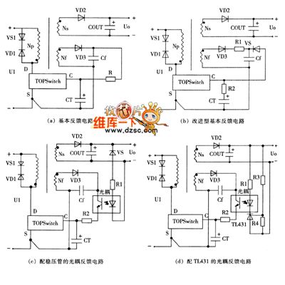
The feedback design style circuit of the switch power supply
Published:2011/6/26 22:36:00 Author:Borg | Keyword: feedback, power supply
View full Circuit Diagram | Comments | Reading(681)
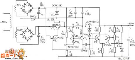
The 150V regulated power supply circuit
Published:2011/6/27 9:58:00 Author:Borg | Keyword: regulated power supply
View full Circuit Diagram | Comments | Reading(1608)
| Pages:204/291 At 20201202203204205206207208209210211212213214215216217218219220Under 20 |
Circuit Categories
power supply circuit
Amplifier Circuit
Basic Circuit
LED and Light Circuit
Sensor Circuit
Signal Processing
Electrical Equipment Circuit
Control Circuit
Remote Control Circuit
A/D-D/A Converter Circuit
Audio Circuit
Measuring and Test Circuit
Communication Circuit
Computer-Related Circuit
555 Circuit
Automotive Circuit
Repairing Circuit