
Index 212
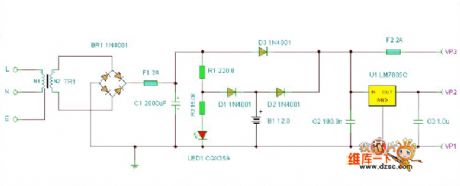
The basic UPS power supply principle circuit
Published:2011/6/21 6:26:00 Author:qqtang | Keyword: UPS, power supply
View full Circuit Diagram | Comments | Reading(1243)
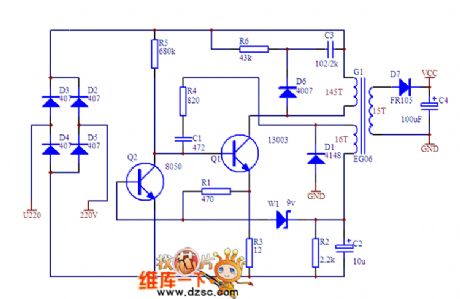
The single terminal flyback switch power supply circuit
Published:2011/6/21 6:58:00 Author:qqtang | Keyword: single terminal, flyback switch
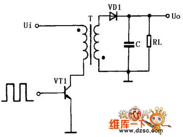
The single terminal flyback switch power supply application circuit is shown in figure 3. The so-called single term means the magnet circuit side of the core in the high-frequency transformer. The so-called flyback means when the switch VT1 is conducting, the inductive voltage of primary coil in the high frequency transformer T is positive in the upper part by passive in the lower part, the rectifier diode VD1 is blocked and save power in the primary coil. When the switch pipe VT1 is blocked, the power stored by the primary coil is delivered to the load after it has been past the coil, rectified by VD1 and filtered by capacitor C.
(View)
View full Circuit Diagram | Comments | Reading(710)
The simple but special regulated circuit
Published:2011/6/21 2:14:00 Author:Seven | Keyword: regulated circuit
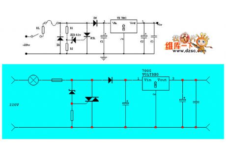
The simple but special regulated circuit: In some conditions, if there needs a regulated circuit while it is running with load, as the control and detector, this circuit will seem brief and convenient. By adjusting the ratio of R1 and R2, the input voltage of the regulated module can be changed, the value of C1 is relative to the loading. A. If the single way thyristor is switched in to dual way thyristor, the circuit will be simpler. (View)
View full Circuit Diagram | Comments | Reading(689)
The 9V battery strainmeter signal adjusting circuit
Published:2011/6/20 22:21:00 Author:Seven | Keyword: 9V battery, strainmeter signal
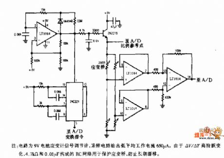
The 9V battery strainmeter signal adjusting circuit is shown as above.Notes: this is a 9V battery strainmeter signal adjusting circuit, the sampling circuit offers the low average working current of 650μA. As ΔV/ΔT jumps in a high order, the RC net composed of 4.7KΩ and 0.01μF is used to protect the reaction bridge, which avoids the long-term drifting.
(View)
View full Circuit Diagram | Comments | Reading(732)
circuit of transistor and current foldback
Published:2011/6/14 9:31:00 Author:chopper | Keyword: transistor, current foldback
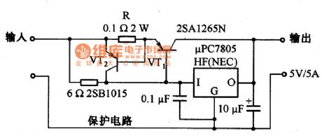
The following picture is the current foldback circuit.When the voltage drop on R is over 0.6V,VT2 will be conducted and VT1 will close to cut off the output current.In this case,the current of VT1 is limited at 6A.
(View)
View full Circuit Diagram | Comments | Reading(1556)
STR-S6309 switching power supply thick film integrated circuit
Published:2011/6/15 7:33:00 Author:chopper | Keyword: switching power supply, thick film
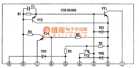
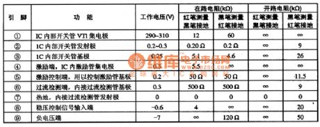
STRS6309 is a mixed type switching power supply thick film integrated circu (View)
View full Circuit Diagram | Comments | Reading(2364)
heat conduction prevention circuit
Published:2011/6/11 21:13:00 Author:chopper | Keyword: heat conduction, prevention
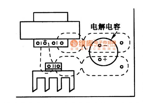
The collocation method is as follows.
(View)
View full Circuit Diagram | Comments | Reading(785)
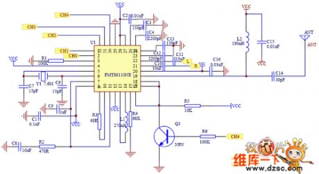
The DEMO-80110NE circuit
Published:2011/6/19 20:50:00 Author:qqtang | Keyword: circuit
View full Circuit Diagram | Comments | Reading(538)
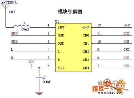
The DEMO-80110NE module pin circuit
Published:2011/6/19 20:49:00 Author:qqtang | Keyword: module pin circuit
View full Circuit Diagram | Comments | Reading(545)
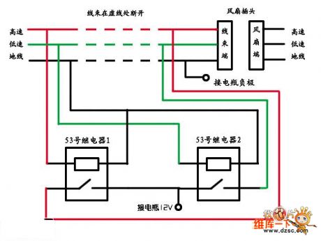
The relay circuit modified from electric fans
Published:2011/6/19 20:49:00 Author:qqtang | Keyword: relay circuit, electric fans
View full Circuit Diagram | Comments | Reading(590)
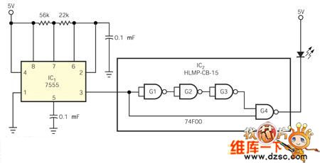
The portable high-speed light pulse generating circuit
Published:2011/6/19 21:42:00 Author:qqtang | Keyword: high-speed, light pulse
View full Circuit Diagram | Comments | Reading(640)
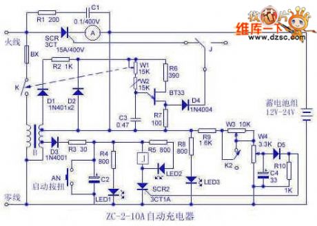
The auto charging motor circuit
Published:2011/6/19 21:45:00 Author:qqtang | Keyword: charging motor
View full Circuit Diagram | Comments | Reading(591)
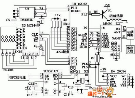
The principle diagram of the bus non-contact IC reader/writer circuit
Published:2011/6/19 21:48:00 Author:qqtang | Keyword: principle diagram, non-contact IC
View full Circuit Diagram | Comments | Reading(625)
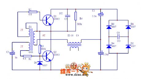
The regulated micro switch power supply circuit
Published:2011/6/19 3:49:00 Author:Seven | Keyword: switch power supply
View full Circuit Diagram | Comments | Reading(1144)
The micro intermediate power switch power supply circuit
Published:2011/6/19 7:44:00 Author:Seven | Keyword: intermediate power, power supply
View full Circuit Diagram | Comments | Reading(949)
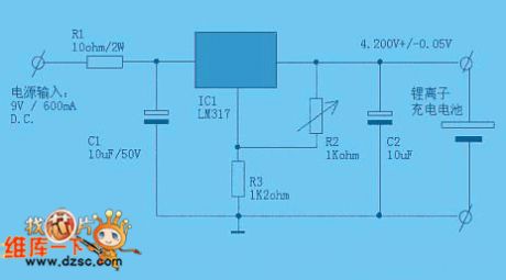
The simplest standard Li-ion battery charger circuit
Published:2011/6/19 8:07:00 Author:Seven | Keyword: battery charger
View full Circuit Diagram | Comments | Reading(736)
Jin Niu charger circuit
Published:2011/6/19 7:25:00 Author:Seven | Keyword: charger, Jin Niu
View full Circuit Diagram | Comments | Reading(710)
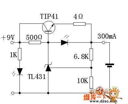
The simple and practical Lithium charger circuit
Published:2011/6/19 8:22:00 Author:Seven | Keyword: Lithium charger
View full Circuit Diagram | Comments | Reading(664)
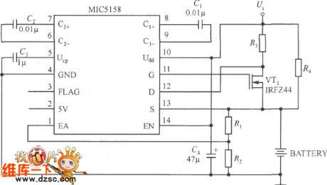
MIC5158--the battery charger circuit
Published:2011/6/19 1:17:00 Author:Seven | Keyword: battery charger
View full Circuit Diagram | Comments | Reading(671)
The op-amp feedback serial connection voltage stable circuit
Published:2011/6/19 1:26:00 Author:Seven | Keyword: op-amp feedback, serial connection
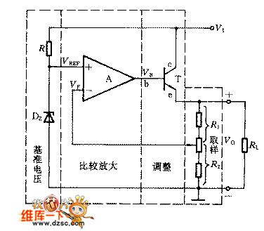

In the figure is the serial connection voltage stable circuit composed of op-amps, which consists of the reference voltage, comparing amplifier, control tube and sampling circuit, 4 parts in total.
Voltage stabilizing process:
Voltage stabilizing range:Therefore, the output voltage of the steady circuit ranges depending on R1/R2. (View)
View full Circuit Diagram | Comments | Reading(620)
| Pages:212/291 At 20201202203204205206207208209210211212213214215216217218219220Under 20 |
Circuit Categories
power supply circuit
Amplifier Circuit
Basic Circuit
LED and Light Circuit
Sensor Circuit
Signal Processing
Electrical Equipment Circuit
Control Circuit
Remote Control Circuit
A/D-D/A Converter Circuit
Audio Circuit
Measuring and Test Circuit
Communication Circuit
Computer-Related Circuit
555 Circuit
Automotive Circuit
Repairing Circuit