
Index 217
Camera Nickel-cadmium Battery Discharger Circuit
Published:2011/5/17 8:04:00 Author:Joyce | Keyword: Camera, Nickel-cadmium Battery, Discharger
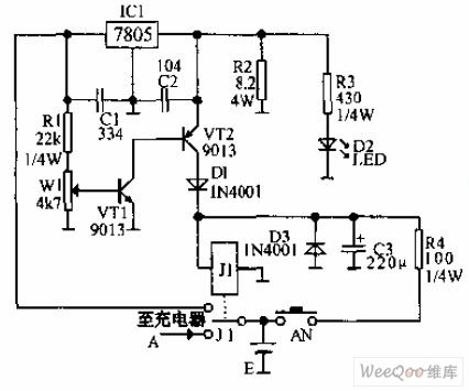
Camera Nickel-cadmium Battery Discharger Circuit is shown in the graph below.After preshing AN, J1 will actuate. At this time, because the voltage on the end of the battery is high, the potential,which has been divided by R1 W1 and then been injected into the baseVT is also high.Both VT1 and VT2 will breakover,and J1 will actuate to protect itself. The battery discharges mainly through IC1, R2, and the indicator light D2 will be on. When the battery voltage drops till it is insufficient for VT1 to breakover, J1 will discharge until its normally open contact disconnects. And when its normally close contact gets through charging circuit A,battery charging begins.
(View)
View full Circuit Diagram | Comments | Reading(1134)
Mini UPS Circuit Digram
Published:2011/5/20 18:51:00 Author:leo | Keyword: Mini UPS Circuit Digram, LT1372
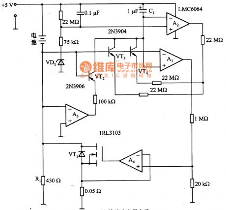
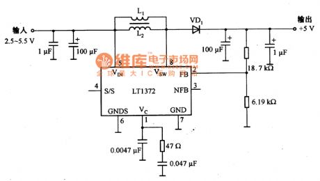
As what is shown in the picture, a and b are mini-UPS-circuits which are made up of quick charger circuit and main circuit. Picture 2(a) is quick charger circuit which use the way of quick charge to extend the life of the battery. The circuit made up of the operational amplifiers of A1 to A4 and related components manages the three working mode of the battery, which are charging, discharging and recharging. During charging the battery, it needs about 0.5A current and two to three hours. (View)
View full Circuit Diagram | Comments | Reading(2444)
Current Detection Circuit Diagram made up of LT1620 and Others
Published:2011/6/2 11:20:00 Author:leo | Keyword: Current Detection Circuit Diagram made up of LT1620 and Others, T1620
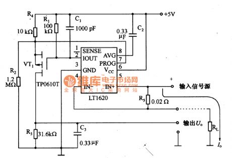
The picture shows a current detection circuit made up of LT1620 and so on. In this circuit, LT1620 is a integrated controller of voltage regulation power in the battery recharger. In the work mode, the LT1620 can produce load current signals under the +5V voltage.Itis madeup of a circuit with MOSFET(VT1) and other external devices to change the load current signals to output voltage based on the location. Therefore, the voltage can give a reflection of the change of load current I. (View)
View full Circuit Diagram | Comments | Reading(802)
BA6235F-The stable integrated circuit of D.C motors
Published:2011/5/17 20:49:00 Author:Borg | Keyword: integrated circuit D.C, motors
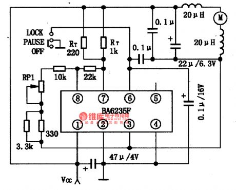
BA6235F a stable integrated circuit of D.C motors produced by Toyo Corp.,Japan, which is always used in Walk-man and radios.1.the typical application circuit of BA6235FThe application circuit of BA6235F chips is as shown in Figure 1.
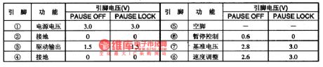
2.pin functions and data of BA6235F BA6235F is a stable integrated circuit of D.C motors, which is in flat 8-lead dual-line package, and its pin functions and data is listed in Table 1.
3.notes for fault detecting and repairing If we want to judge whether BA6235F is malfunctioning, we can test the values of pinning voltages and compare them with common values. (View)
View full Circuit Diagram | Comments | Reading(719)
Main technology parameters of Citroen ZX and DPCA-VOLCANE
Published:2011/5/19 21:40:00 Author:Borg | Keyword: Main technology parameters, Citroen ZX, DPCA-VOLCANE
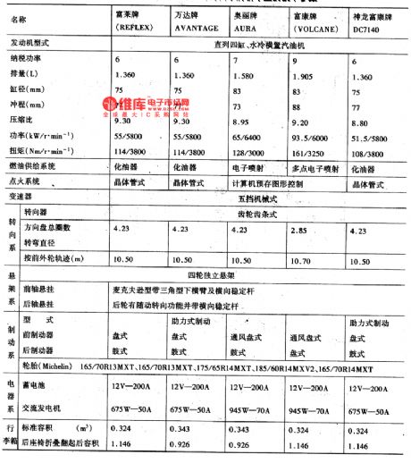

Citroen ZX, France, has many makes, the emission of RE-FLEX and AVANTAGE is 1.36L, and they are fixed with carburetor engines; both the AURA of 1.580L and VOLCANE of 1.905L use the electric control petrol injection engine. By far, the parameters of DPCA-VOLCANE DC7140 (1.6L) are close to that of RE-FLEX. The technology parameters of cars of all makes are listed in the table. Main technology parameters of Citroen ZX and DPCA-VOLCANE
(View)
View full Circuit Diagram | Comments | Reading(946)
Double closed loop control of electric bicycle charger circuit principle diagram
Published:2011/6/3 21:44:00 Author:Fiona | Keyword: Double closed loop control, electric bicycle charger
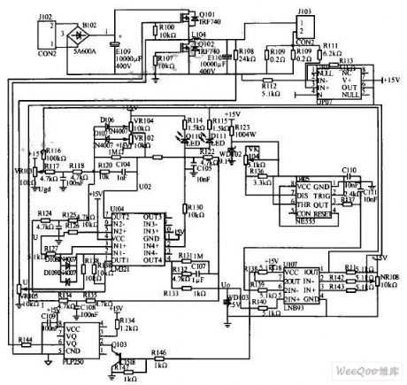
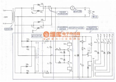
The charger is specifically designed for electric bicycle battery, it rectifys AC then uses IGBT to pressure regulating to achieve the charging voltage that the battery needs is about 3 6 V, control through the voltage and the current double closed loop to achieve the three-stage charging purposes. Chargers mainly consists of the major circuit and control circuit.The circuit principle is shown in the diagram. (View)
View full Circuit Diagram | Comments | Reading(3745)
The nonpolarity charging circuit
Published:2011/6/9 0:13:00 Author:Seven | Keyword: charging circuit
View full Circuit Diagram | Comments | Reading(692)
Steady operation circuit diagram
Published:2011/6/8 23:00:00 Author:Sophia | Keyword: Steady operation

(View)
View full Circuit Diagram | Comments | Reading(653)
The circuit diagram of emergency lamp circuit board
Published:2011/5/24 23:36:00 Author:Ariel Wang | Keyword: emergency lamp, circuit board
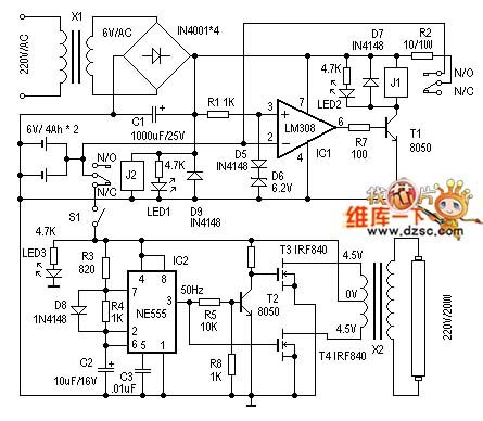
When we make it,X1selects secondary power transformer 6V/200mA for use. J1 and J2 use the relay of 6V coil voltage.Othe device selection you can refer to the diagram. There's no other requirements.It's very easy for circuit debugging.When main power supply is connected.J2 should act.LED1 is the indication of power supply. Then measurethe 3 leg voltage ,see if it is around 6.9V.After that it's possible to use external power to access IC 2 feet to adjust chargement to protect circuit. When input voltage is beyond 6.9V,J1 should disconnect . When S1 is disconnected,you can use external power to access emergency lamp circuit.Then you can measurewhether the output of IC2 is 50Hz or not.Then it's possible to measure wether partial output voltage of X2 is around 220V.LED3 is theprediction ofwhether it is power failure or normal working status of emergency lamp.
(View)
View full Circuit Diagram | Comments | Reading(2676)
switching-regulator circuit reformed by waste energy-saving lamp
Published:2011/5/24 23:45:00 Author:Ariel Wang | Keyword: switching-regulator circuit, waste, evergy-saving lamp
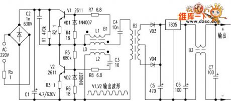
When it isbeingused,it's not proper to take voltage from C5 directly. It's imposible to allow short circuit happened, otherwise it'll burn V1 and V2. Because when short circuit takes place,the electric currentin coil LO of flyback transformer B1 will increase rappidly.The voltage of coil L1 and L2 increases to a rather high level.It gives back the electric currentin V1 and V2 increasing as well. It causes intensive positive feedback.Finally it burns out as the limitation of power consumption of V1 and V2. This feedback of circuit belongs to series circuit feedback.And it can openand protectcircuit. But when load is increased,the feedback is strenghened.What's more,the frequency will decrease as the load increases. The internal resistance is rather small,so short circuit will burn pliotron very easily.
(View)
View full Circuit Diagram | Comments | Reading(1029)
Switching power supply of artificial circuit diagram
Published:2011/6/2 21:45:00 Author:Sophia | Keyword: Artificial circuit, Switching power supply
(View)
View full Circuit Diagram | Comments | Reading(817)
Sawtooth Wave Generating Circuit with Optional Slope and Amplitude
Published:2011/6/6 1:06:00 Author:Michel | Keyword: Sawtooth Wave, Generating Circuit, Optional Slope and Amplitude
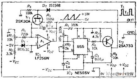
Circuit's FunctionsSawtooth wave can be used as scanning signals and it is a kind of waveform that voltage rises in linear way with the time. This waveform forms mostly by using capacitor constant-current charging and discharging method.This circuit changes output voltage and frequency through altering integration circuit's timing.Waveform slope can be setted by changing integration input current.
Circuit's Wrok PrincipleThe integrators A1 starts ponits in VR1 current when the power is switched on.The timer produces timing pulse according to certain time interval. (View)
View full Circuit Diagram | Comments | Reading(1146)
Phase-shifting Control Circuit of 1000W Full Bridge Soft Switching Power Supply
Published:2011/6/7 0:19:00 Author:Michel | Keyword: 1000W, Full Bridge, Soft Switching, Power Supply, Phase-shifting, Control Circuit
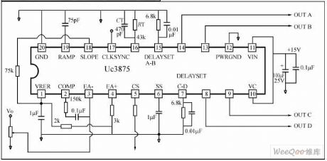
1000W full bridge soft switching power supply IC control system of application 100kHz,1000W phase-shifting control and its circuit is showed as the picture 1.Picture 1:Phase-shifting Control Application Circuit Composed of UC3875 etc. (View)
View full Circuit Diagram | Comments | Reading(2961)
Typical Application Circuit of UC3842 Overvoltage and Overcurrent Protection
Published:2011/6/7 0:08:00 Author:Michel | Keyword: Overvoltage and Overcurrent Protection, Typical Application Circuit
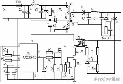
The typical application circuit of UC3842 overvoltage and overcurrent protection picture is showed as above.
Overcurrent Protection Principle
When load current exceeds rating value or the output shorts,which causes that current is added to switch tube V4 ,R7's voltage feedbacks to feet.When R7's voltage exceeds 1V and the conduction width narrows down cuased by inside current amplifier and the output voltage drops,meanwhile it makes the UC3842 work's voltage drop.When it is lower thansetting voltage,over-current protection circuit starts to work to protect power tube.Power supply resumes work when short circuit phenomenon vanishes.
(View)
View full Circuit Diagram | Comments | Reading(10617)
The sound and light alarm circuit diagram 2 for industrial instrumentation
Published:2011/6/9 4:33:00 Author:Lucas | Keyword: sound , light alarm, industrial instrumentation
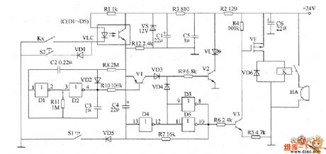
The sound and light alarm circuit for industrial instrumentation is composed of the +12 V voltage-stabilizing circuit, switch control circuit, oscillator, bistable flip-flop, sound and light alarm circuit, and the circuit is shown as the chart. +12 V voltage-stabilizing circuit consists of resistors R2, R3, filter capacitors C1, C5, C6 and regulator diode VS. Switch control circuit consists of resistors R1, R12, optocoupler VLC and industrial instrumentation control contact (controlled electrical contact) Kx. Oscillator is composed of the D1, D2 which are inside of NOT gate IC IC (D1 ~ D5) and diode VD2, resistor R11, capacitors C2, C3. Bistable flip-flop is composed of the D3 ~ D5 which are inside of IC and resistor R7.
(View)
View full Circuit Diagram | Comments | Reading(1045)
the temperature measurement circuit Constituted by the microcomputer and others
Published:2011/5/18 1:56:00 Author: | Keyword: temperature measurement circuit, microcomputer , LM324, ADC0808

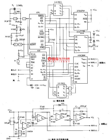
Figure (b) shows the temperature and voltage conversion circuit.It is consist of Al-A4 operational amplifier LM324, VD2 regulator and VDl temperaturesensor and so on. By using the change of forward voltage of diode VDl's PN junction to the linear change of temperature, we converte the temperature to voltage.The work's power supply of the operational amplifier is generally positive and negative dual power.However, when the +5 V single power supply is working, we use LM324 which uses 士1·5V and circuit which uses A1 as midpoint voltage.ADCO808 uses the way of simulation to Connecte to midpoint voltage. The reference voltage is connected to ADC0808's V(REF)(+) port by the diode of 2v stable voltage VD2 which is through A2. (View)
View full Circuit Diagram | Comments | Reading(738)
Thermocouple linearization circuit
Published:2011/5/18 3:20:00 Author: | Keyword: Thermocouple linearization circuit
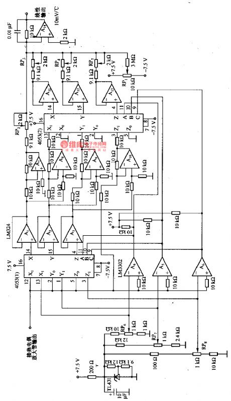
This figure shows the thermocouple linearization circuit. It uses broken line approximation method to execute linearization. It sets the breakpoints by the order from RP6 to RP8 and adjusts every broken line's gain by RP2一RP5,s. RP1 is for zero adjustment. Adjusting the RP1 to make the Offset voltages of Thermocouple Amplifier and that of Operational Amplifier Counteract to make sure when intputting is zero, the outputting is zero too. To J type thermocouple, the breakpionts are set at 70℃、110℃and 520℃ and its linearization debouchement is at the rage from 0℃一600℃ and the precision is in 士0•5℃. (View)
View full Circuit Diagram | Comments | Reading(1346)
AC Voltage Regulator Twelve
Published:2011/6/3 6:54:00 Author:Michel | Keyword: AC, Voltage Regulator, Twelve
The AC voltage regulator uses servo-type control circuit which has wide voltage regulation range(The input AC voltage range is 160-260V)and high control accuracy.This circuit is easy to make and suitable for where the utility power is unstable.
Circuit's Work Principle
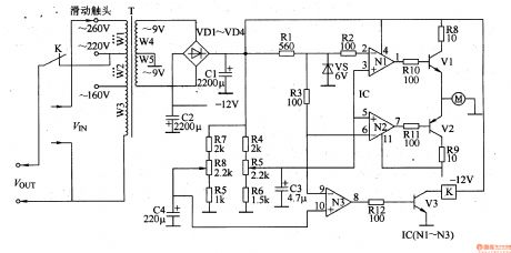
The AC voltage regulator circuit is composed of 士l2V mains circuirt ,voltage test circuit and overvoltage protection circuit and it is showed as the picture 5-51.The 士l2V power supply circuit consists of powerstat,W4 and W5,commutation diode,VD1-VD4 and filter capacitor C1 and C2. (View)
View full Circuit Diagram | Comments | Reading(2577)
AC Voltage Regulator Eleven
Published:2011/6/3 7:47:00 Author:Michel | Keyword: AC, Voltage Regulator, Eleven
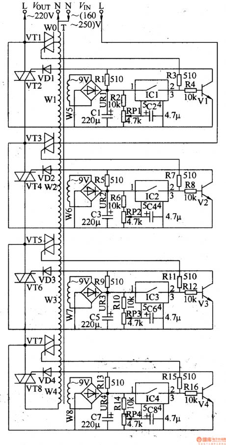
This example introduces an AC regulator composed of electronic switching IC and thyristor etc.Comparedwith the AC voltage regulator whose voltage converts by relay,it has no mechnical converting noises and momentary breakdown with long performance life.The regualtor can make sure the output voltage is 220V士l0V when the input AC voltage alters between 160-250V.
Circuit's Wrok Principle
The regulator circuit consists of four groups of stabilized voltage control circuit and it is showed as the picture 5-50.The first group stabilized voltage control circuit is composed of thyristor VT1,VT2,diode VD1,rectifier bridge UR1,resistor R1-R4, potentiometer RP1,capacitor C1,C2,electronic switching Intergrated Circuit IC1,transistor V1 and transformer group's W1 and W2. (View)
View full Circuit Diagram | Comments | Reading(1093)
AC Voltage Regulator Ten
Published:2011/5/22 1:25:00 Author:Michel | Keyword: AC Voltage Regulator, Ten
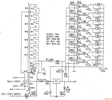
The AC voltage regulator introudced in the example has the features of broad voltage regulation range(102-262V),perfect protection effects(powerdown delay electrification,380V phase dislocation-proofing and lightning protection and statics-proofing etc.) and high sensitivity and it's available in families with unsable line voltage.
Circuit's WorkPrincipleThe AC voltage regulatorcircuit is composed of +5V voltage regulation circuit,voltage test circuit,control circuit,protection circuit and voltage regualation output circuit and it is showed as the picture 5-49.The +5V voltage regulation circuit consists of fuse,FU1-FU3,autotransformer,T,commutation diode,VD1,filter capacitor,C1,three-terminal voltage regulation IC,IC1,resistor,R21 andpowersupply indication LED,VL. (View)
View full Circuit Diagram | Comments | Reading(2508)
| Pages:217/291 At 20201202203204205206207208209210211212213214215216217218219220Under 20 |
Circuit Categories
power supply circuit
Amplifier Circuit
Basic Circuit
LED and Light Circuit
Sensor Circuit
Signal Processing
Electrical Equipment Circuit
Control Circuit
Remote Control Circuit
A/D-D/A Converter Circuit
Audio Circuit
Measuring and Test Circuit
Communication Circuit
Computer-Related Circuit
555 Circuit
Automotive Circuit
Repairing Circuit