
Index 211
12V/24V lead-acid battery charging circuit
Published:2011/6/23 1:35:00 Author:TaoXi | Keyword: 12V/24V, lead-acid battery, charging circuit

The LM339 simple lead-acid battery charging circuit is as shown in the figure, you can use two 24V lead-acid batteries as the power supply.
(View)
View full Circuit Diagram | Comments | Reading(6219)
BG602 charger circuit
Published:2011/6/16 22:14:00 Author:chopper | Keyword: charger circuit
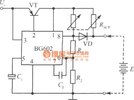
View full Circuit Diagram | Comments | Reading(836)
A3 norm power supply circuit
Published:2011/6/14 8:24:00 Author:chopper | Keyword: power supply
View full Circuit Diagram | Comments | Reading(725)
The electric energy-saving lamp circuit
Published:2011/6/20 0:39:00 Author:Seven | Keyword: energy-saving lamp
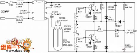
View full Circuit Diagram | Comments | Reading(3248)
The light touch switch circuit
Published:2011/6/20 0:44:00 Author:Seven | Keyword: switch circuit
View full Circuit Diagram | Comments | Reading(649)
The single key switch circuit (2)
Published:2011/6/20 0:48:00 Author:Seven | Keyword: key switch
View full Circuit Diagram | Comments | Reading(1039)
The self-motivated switch stable power supply circuit (1)
Published:2011/6/16 20:28:00 Author:qqtang | Keyword: self-motivated, power supply
The self-motivated switch stable power supply circuit (1) is shown in the following figure:
(View)
View full Circuit Diagram | Comments | Reading(658)
The 70v stable power supply circuit
Published:2011/6/22 2:11:00 Author:Borg | Keyword: stable, power supply
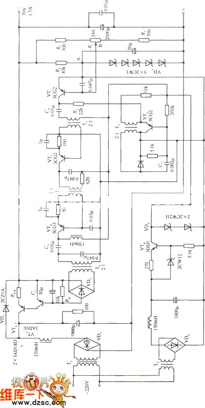
View full Circuit Diagram | Comments | Reading(747)
The 10~65V stable power supply circuit
Published:2011/6/22 1:45:00 Author:Borg | Keyword: stable power supply
View full Circuit Diagram | Comments | Reading(611)
The 120V regulated power supply circuit
Published:2011/6/22 1:40:00 Author:Borg | Keyword: regulated, power supply circuit
View full Circuit Diagram | Comments | Reading(962)
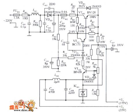
The 175v regulated power supply circuit
Published:2011/6/22 3:12:00 Author:Borg | Keyword: regulated, power supply
View full Circuit Diagram | Comments | Reading(783)
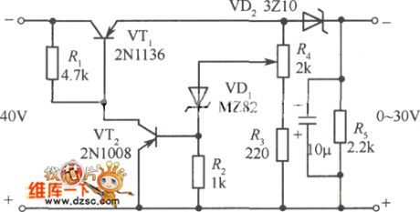
The 0~30v simple steady power supply circuit
Published:2011/6/22 3:58:00 Author:Borg | Keyword: power supply
View full Circuit Diagram | Comments | Reading(614)
The touch switch circuit composed of the phase inverter (2)
Published:2011/6/20 10:52:00 Author:Seven | Keyword: touch switch circuit, phase inverter
View full Circuit Diagram | Comments | Reading(644)
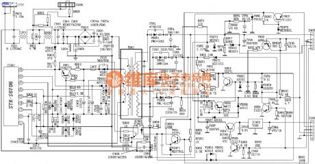
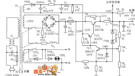
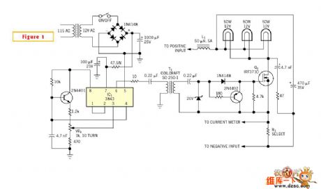
The STK4142 application circuit
Published:2011/6/20 22:09:00 Author:Seven | Keyword: application circuit
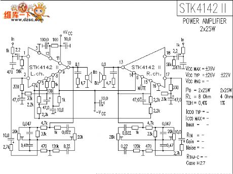
The STK4142 application circuit is shown in the above figure.
(View)
View full Circuit Diagram | Comments | Reading(8799)
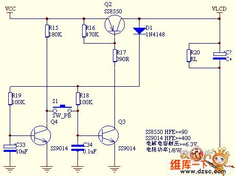
The stable single key electric switch circuit
Published:2011/6/20 0:51:00 Author:Seven | Keyword: single key, switch circuit
View full Circuit Diagram | Comments | Reading(674)
The full-bile rectifier regulated circuit
Published:2011/6/21 1:53:00 Author:Seven | Keyword: full-bile, rectifier
The full-bile rectifier regulated circuit is shown as above.
(View)
View full Circuit Diagram | Comments | Reading(608)
The power supply over current protection circuit of the ring switch
Published:2011/6/16 20:16:00 Author:qqtang | Keyword: power supply, protection circuit
The power supply over current protection circuit of the ring switch is shown in the following circuit:
(View)
View full Circuit Diagram | Comments | Reading(714)
The general power supply loading circuit with the usage of bulbs
Published:2011/6/21 22:28:00 Author:qqtang | Keyword: power supply, bulb
View full Circuit Diagram | Comments | Reading(782)
Operational amplifier anti-blocking circuit
Published:2011/6/13 4:51:00 Author:Christina | Keyword: Operational amplifier, anti-blocking
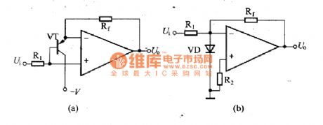
If we add the large signal or the larger interference to the reverse phase input port of the operational amplifier, the amplifier always can't work normally, and there will be the phenomenon of the signal can not enter the amplifier or the output intermittent, at this time, you must turn off the power supply then turn on again or remove the signal for a period of time, so the amplifier can return to normal. This phenomenon called the blockade or the lockout. This phenomenon is caused by: the transistor of the input stage is saturated, the reverse phase input port and output port lose the nature of the opposite phase, so the circuit changes into the positive feedback.
(View)
View full Circuit Diagram | Comments | Reading(663)
Feedback circuit
Published:2011/6/13 6:50:00 Author:Christina | Keyword: Feedback
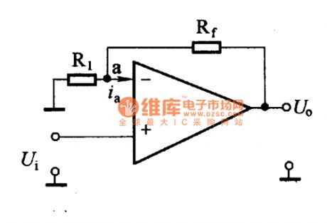
In the practical applications, we usually need to add the feedback circuit to the operational amplifier. Because the open-loop gain of the operational amplifier is high, but in the practical applications the open-loop gain of the operational amplifier is not high, so we need to add the negative feedback circuit to form the closed loop to get the corresponding functions. In addition, in the depth feedback conditions, the performance of the operational amplifier will be much better.
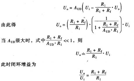
Same-phase input feedback amplifier circuit
The figure shows the same-phase input feedback amplifier circuit. We add the negative feedback resistance Rf from the output port to the reverse phase input, the input voltage is input from the same-phase port.
According to the open loop voltage gain expression, we can list:
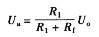
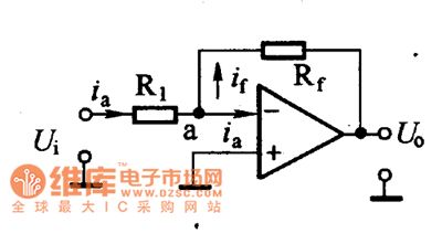
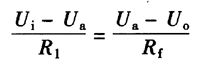
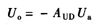
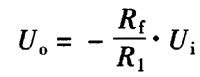
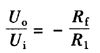
Reverse phase input feedback amplifier circuit:
Closed-loop gain:
The negative sign of the formula means the phase position of the output voltage and the input voltage is opposite. The formula shows that as long as the AUD is large enough, the closed-loop gain of this amplifier is only decided by the ratio of the resistance Rf and resistance R1, it has nothing to do with other parameters. (View)
View full Circuit Diagram | Comments | Reading(871)
| Pages:211/291 At 20201202203204205206207208209210211212213214215216217218219220Under 20 |
Circuit Categories
power supply circuit
Amplifier Circuit
Basic Circuit
LED and Light Circuit
Sensor Circuit
Signal Processing
Electrical Equipment Circuit
Control Circuit
Remote Control Circuit
A/D-D/A Converter Circuit
Audio Circuit
Measuring and Test Circuit
Communication Circuit
Computer-Related Circuit
555 Circuit
Automotive Circuit
Repairing Circuit