
Index 216
Multifunction Charger Ten
Published:2011/5/19 9:33:00 Author:Michel | Keyword: Multifunction Charger Ten
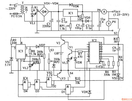
This example introduces one multifunction automatical battery charger.Besides charging nickel-cadmium battery,this charger also can provide low capacity lead-acid and plain dry cells supplementary charging and still can be used as stabilized voltage supply.
Circuit's Work Principle
The charger is composed of stabilized voltage supply circuit,timer,impulsator,charger circuit and control circuit and it is showed as the picture 5-72.The stabilized voltage consists of mains switch,S1,fuse plug,mains transformer,T,power indication LED,VD1,commutation diode,VD1-VD4,three-terminal voltage regulation IC,IC1,potentiometer,RP1,ammeter,PA,voltmeter,PV,resistor,R1 and R2,capacitor,C1and diode,VD5 and VD6. (View)
View full Circuit Diagram | Comments | Reading(1118)
Lithium-ion Battery Charger One
Published:2011/5/19 22:17:00 Author:Michel | Keyword: Lithium-ion Battery Charger, One
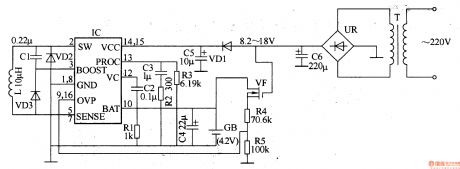
The lithium-ion rechargeable battery charger introduced in the example charges in constant voltage and current way.It is suitable for 3.6V
lithium ion battery charging which are used in kinds of mobile phones.
Circuit's Work Principle
The lithium-ion rechargeable battery charger consists of battery charger circuit,charging control circuit and protection circuit and it
is showed as the picture 5-73.Power supply circuit is composed of mains transformer,T,rectifier bridge,UR and filter capcitor,C6.
Charging control circuit consists of special intergrated circuit,IC,resistor,R1-R3,capacitor,C1-C5,diode,VD1-VD3 and inductor. (View)
View full Circuit Diagram | Comments | Reading(3732)
Lithium-ion Battery Charger Two
Published:2011/5/19 22:12:00 Author:Michel | Keyword: Lithium-ion Battery Charger , Two
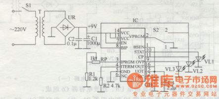
The lithium-ion rechargeable battery charger introduced in the example is made from new type intelligent charging special IC,SC801.It has the functions of overvoltage,overcurrent,overtemperature protection and charging status indication which can choose charging mode according to the batteries and stop charging when the batteries are fully charged automatically.
Circuit's Work Principle
The circuit of this lithium-ion rechargeable battery charger consists of power supply circuit and charging control circuit and it is showed as the picture 5-74.Power supply circuit is made of mains switch,S1,mains transformer,T and rectifier bridge,UR and filter capcitor,C1. (View)
View full Circuit Diagram | Comments | Reading(644)
Lithium-ion Battery Charger Four
Published:2011/5/19 22:17:00 Author:Michel | Keyword: Lithium-ion Battery Charger, Four
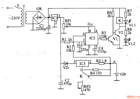
The ionicbond battery charger introduced in the example is made from 555 time-base intergrated circuit.This charger can automatically switch the constant current and voltage charging.That's to say,the charger uses constant charging when the battery's voltage islower than 4.2V and it adopts constant voltage and low current(60mA) charging mode when the battery's voltage reaches 4.2V so there is no overcharging.
Circuit's Work Principle
The lithium-ion battery charger is composed of power supply circuit,charging circuit and control circuit and it is showed as the picture 5-76.
(View)
View full Circuit Diagram | Comments | Reading(1974)
D. C. Regulated Power Supply of High Voltage Two
Published:2011/6/3 3:52:00 Author:Michel | Keyword: High Voltage, D. C., Regulated Power Supply, Two
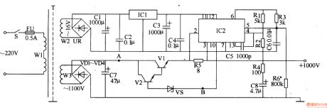
The high voltage D. C. regulated power supply circuit introduced in the example uses floated voltage regulating pattern and its output voltage is 1000V and output current is 100mA.It can be used in high-voltage instruments and meters.
Work's Principle of the Circuit
The high voltage D. C. regulated power supply circuit is composed of input converting circuit and voltage regulation output circuit and it is showed as the picture 5-36.The input converting circuit consists of mains switch,S,fuse,FU,mains transformer,T,rectifier bridge,UR and commutation diode,VD1-VD4.The voltage regulation output circuit consists of integrated regulator,IC1,IC2,transistor,V1,V2,voltage regulator diode,VS,capacitor,C1-C8 and resistor,R1-R6. (View)
View full Circuit Diagram | Comments | Reading(2292)
Numerical Control D. C. Regulated Power Supply Thirteen
Published:2011/6/2 11:11:00 Author:Michel | Keyword: Numerical Control, D. C., Regulated Power Supply, Thirteen
The numerical control D. C. power-supply circuits-fixed introduced in the example only uses one touch electrode and its magnitude of output voltage are divided into 8 grades,namely,3V,4.5V,5V,6V,7.5V,9V,12V and 15V.Its maximum current is 2A.
Work's Principle of the Circuit
The numerical control D. C. power-supply circuits-fixed consists of constant voltage control circuit and touch control circuit and it is showed as the picture 5-30.The constant voltage control circuit is composed of mains switch,S,fuse,FU1,FU2,mains transformer,T,commutation diode,VD1-VD4,capacitor,C1-C4,C6,resistor,RO,R1,voltage regulator diode,VS and three-terminal integrated regulator,IC1. (View)
View full Circuit Diagram | Comments | Reading(1089)
Numerical Control D. C. Regulated Power Supply Tweleve
Published:2011/6/2 11:11:00 Author:Michel | Keyword: Numerical Control, D. C., Regulated Power Supply, Tweleve
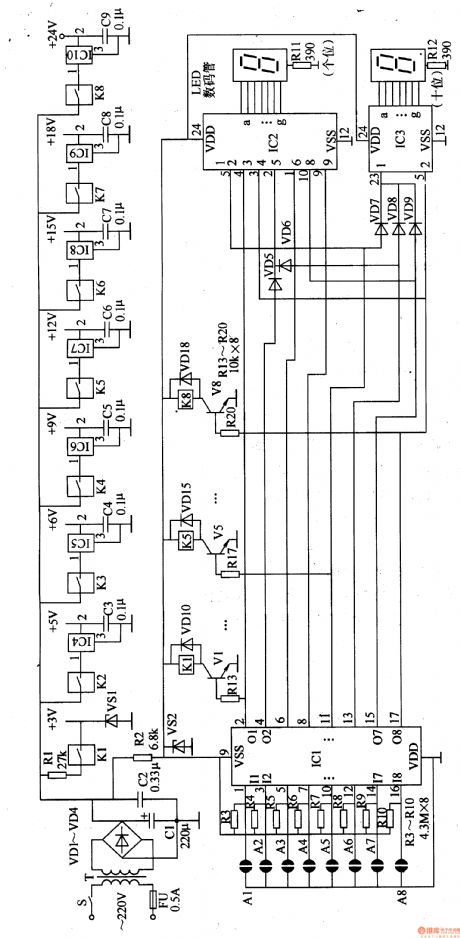
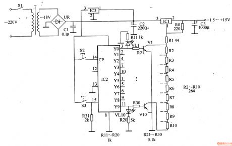
The numerical control D. C. power-supply circuits-fixed introduced in the example controls the magnitude of the voltage by touching the sheet metal by fingers.Its magnitudeof the output voltage are divided into 8 gardes ,namely,1.5V,3V,4.5V,6V,7.5V,9V and 12V which uses LED to indicate and it's convenient.
Work's Principle of the Circuit
The numerical control D. C. power-supply circuits-fixed is composed of trigger generator circuit and counter,encoder,,switch control circuit and constant voltage and it is showed as the picture 5-31.
The trigger generator circuit consists of touching sheet metal,A1,A2,NOT-gate IC1(D1-D4),NOT-gate IC,IC2(D5,D6),resistor,R1-R4,capacitor,C1-C4. (View)
View full Circuit Diagram | Comments | Reading(1211)
Numerical Control D. C. Regulated Power Supply Eleven
Published:2011/6/2 11:10:00 Author:Michel | Keyword: Numerical Control, D. C., Regulated Power Supply, Eleven
The numerical control D. C. power-supply circuits-fixed introduced in the example only uses one touch electrode and its magnitude of output voltage are divided into 8 grades,namely,3V,4.5V,5V,6V,7.5V,9V,12V and 15V.Its maximum current is 2A.
Work's Principle of the Circuit
The numerical control D. C. power-supply circuits-fixed consists of constant voltage control circuit and touch control circuit and it is showed as the picture 5-30.The constant voltage control circuit is composed of mains switch,S,fuse,FU1,FU2,mains transformer,T,commutation diode,VD1-VD4,capacitor,C1-C4,C6,resistor,RO,R1,voltage regulator diode,VS and three-terminal integrated regulator,IC1. (View)
View full Circuit Diagram | Comments | Reading(1165)
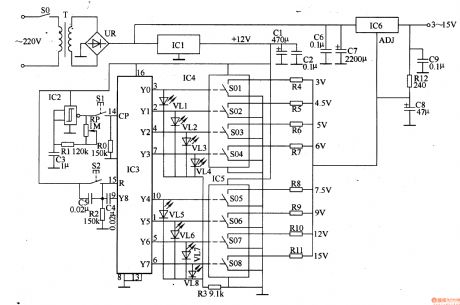
Numerical Control D. C. Regulated Power Supply Ten
Published:2011/6/2 11:09:00 Author:Michel | Keyword: Numerical Control, D. C., Regulated Power Supply, Ten
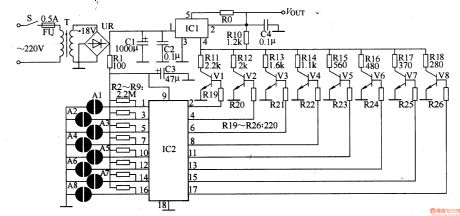
The output voltage of the numerical control D. C. power-supply circuits-fixed introduced in the example are divided into 8 grades,namely,3V,4.5V,5V,6V,7.5V,9V,l2V and l5V.Its maximum current is 2A.
Work's Principle of the Circuit
The numerical control D. C. power-supply circuits-fixed consists of constant voltage control circuit and touch control circuit and it is showed as the picture 5-29.
The constant voltage control circuit is composed of mains switch,S,fuse,FU,mains transformer,T,rectifier bridge,UR,filter capacitor,C1 and five-terminal adjustable integrated regulator,IC2.The touch control circuit is composed of touch electrode slice,A1-A8,resistor,R1-R6,transistor,V1-V8 and electronic switching IC,IC2. (View)
View full Circuit Diagram | Comments | Reading(796)
Numerical Control D. C. Regulated Power Supply Nine
Published:2011/6/2 11:08:00 Author:Michel | Keyword: Numerical Control, D. C., Regulated Power Suppl, Nine
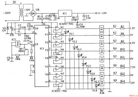
The output voltage of the numerical control D. C. power-supply circuits-fixed introduced in the example is from +1.5V to 12V with 8 adjustable grades and its maximum current is 1.5A.
Work's Principle of the Circuitnumerical control D. C. power-supply circuits-fixed consists of +12V voltage constant voltage control circuit,voltage control or indication circuit and constant voltage output circuit and it is showed as the 5-28 picture.
The +12V voltage constant voltage control circuit consists of mains switch,SO,mains transformer,T,rectifier bridge,UR,resistor,RI,voltage regulator diode,VS,and filter capacitor,C1,C2,C7.The voltage control or indication circuit is composed of reset button,S1,control button,S2,resistor,R2-R6,regulation resistance,RP and capacitor,C5,C6,C8 (View)
View full Circuit Diagram | Comments | Reading(966)
Numerical Control D. C. Regulated Power Supply Eight
Published:2011/6/2 11:07:00 Author:Michel | Keyword: Numerical Control, D. C., Regulated Power Supply, Eight

The numerical control D. C. power-supply circuits-fixed introduced in the example uses control buttons and digital IC and it adopts LED to indicate the magnitude of the output voltage which has 8 grades.Its maximum current is 1.5A.
Work's Principle of the CircuitThe numerical control D. C. power-supply circuits-fixed is composed of +12V voltage constant voltage control circuit,voltage control indication circuit and constant voltage output circuit and it is showed as the 5-27 picture.
The +12V voltage constant voltage control circuit consists of mains transformer,T,rectifier bridge,UR,filter capacitor,C1,C2,C6,C7 and three-terminal integrated regulator,IC1. (View)
View full Circuit Diagram | Comments | Reading(1257)
Numerical Control D. C. Regulated Power Supply Seven
Published:2011/6/2 11:03:00 Author:Michel | Keyword: Numerical Control, D. C., Regulated Power Supply, Seven
The numerical control D. C. power-supply circuits-fixed introduced in the example uses digital IC to control the power-supply circuits-fixed and the user adopts two buttons to regulate the magnitude of the voltage conveniently.
Work's Principle of the Circuit
The numerical control D. C. power-supply circuits-fixed consists of +12V voltage constant voltage control circuit,voltage control circuit and constant voltage output circuit and it is showed as the 5-26 picture.+12Vvoltage constant voltage control circuit is composed of mains switch,SO,mains transformer,T,rectifier bridge,UR,filter capacitor,C1-C3 and three-terminal integrated regulator,IC1. (View)
View full Circuit Diagram | Comments | Reading(922)
Numerical Control D. C. Regulated Power Supply Five
Published:2011/6/2 10:58:00 Author:Michel | Keyword: Numerical Control, D. C., Regulated Power Supply, Five
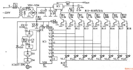
The numerical control D. C. power-supply circuits-fixed introduced in the example uses control button to choose output voltage (range:1.5-15V)and adopts LED to indicate the magnitude of voltage,which is convenient and intuitionistic.
Work's Principle of the Circuit
The numerical control D. C. power-supply circuits-fixed is omposed of power-supply circuits-fixed and ouput voltage control circuitand it is showed as the picture 5-24.
The power-supply circuits-fixed consists of mains switch,S1,mains tranformer,T,rectifier bridge,UR,capacitor,C1-C3,three-terminal integrated regulator,IC1and IC2 and resistor,RO-R1O. (View)
View full Circuit Diagram | Comments | Reading(1106)
AC Voltage Regulator Fourteen
Published:2011/6/3 8:13:00 Author:Michel | Keyword: AC, Voltage Regulator, Fourteen
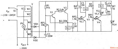
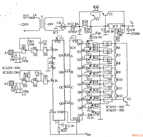
The AC voltage regulator introduced in the example has the functions automatical voltage regulation and overvoltage protection.Its input voltage range is 150-240V,output voltage is 220V±l0V and output power is 500W.
Circuit's Wrok Principle
The rgulator circuit is composed of voltage test control circuit,boosting or dropping voltage circuit and overvoltage protection circuit and it is showed as the picture 5-53. The voltage test control circuit consists of transformer T,communication diode VD1,VD2,capacitor C1-C3,transistor V1-V3,resistor,R1-R4,potentiometer RP1,RP2 and LED VL1 and relay K1. (View)
View full Circuit Diagram | Comments | Reading(5291)
AC Voltage Regulator Thirteen
Published:2011/6/3 8:33:00 Author:Michel | Keyword: AC, Voltage Regulator, Thirteen
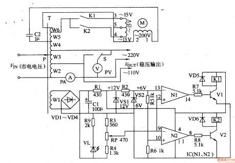
The AC voltage regulator introduced in the example uses servo-type control circuit.It has good dependability and wide adjustable range.
Circuit's Wrok Principle
The circuit is composed of voltage stabilizing circuit,voltage test control circuit and voltage regulation output circuit and it is showed as the picture 5-52.The voltage stabilizing circuit consists of self-coupling transformer,T,communication diode VD1-VD4,filter capacitor CT,current-limitting resistor R1,R2 and voltage regulation diode VS1,VS2.
The voltage test control circuit is composed of R3-R9,diode VD5,VD6,LED VL,relay K1,K2,potentiometer RP,transistor V1,V2 and operational amplifier IC(N1,N2). (View)
View full Circuit Diagram | Comments | Reading(2894)
Switch D. C. Regulated Power Supply Two
Published:2011/6/3 4:39:00 Author:Michel | Keyword: Switch, D. C., Regulated Power Supply, Two
This example introduces the switch D. C. regulated power supply circuit of buck-mode +5V series.It is composed of power supply circuit,impulsator,voltage sampling or pulse width modulation circuit, buffering driver circuit and it is showed as the picture 5-38.The input converting circuit consists of mains transformer,T,commutation diode VD1-VD4,filter capacitor C1,current-limiting resistor and voltage regulator diode VS.The impulsator consists of time-base integrated circuit IC,resistor,R1,R2 and capacitor,C2,C5.The voltage sampling or pulse width modulation circuit is composed of capacitor,C3,resistor,R3-R5,R11-R13 and transistor V4 and V5. (View)
View full Circuit Diagram | Comments | Reading(2849)
Switch D. C. Regulated Power Supply One
Published:2011/6/3 3:52:00 Author:Michel | Keyword: Switch , D. C., Regulated Power Supply, One
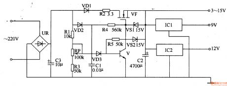
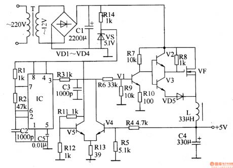
The switch D. C. regulated power supply circuit introduced in the example can supply 3-15V D.C. voltage and its maximum current is 150mA,which meet the miniaturized electronics' power supply.
Work's Principle of the CircuitThe switch D. C. regulated power supply circuit is composed of rectifying and wave-filtering circuit,switch control circuit and voltage regulator circuit and it is showed as the picture 5-37.
The rectifying and wave-filtering bridge,UR,commutation diode,VD1,VD2 and filter capacitor,C1 and C3.The switch control circuit consists of resistor,R2 and R4,voltage regulator diode,VS1 and field effect transistor,VF.The voltage regulator circuit is composed of resistor R1,R3,R5,voltage regulator diode VS2,transistor,V,diode,VD3,filter capacitor C2 and three-terminal integrated regulator IC1 and IC2.
(View)
View full Circuit Diagram | Comments | Reading(1214)
D. C. Regulated Power Supply of High Voltage One
Published:2011/6/3 1:02:00 Author:Michel | Keyword: High Voltage, D. C., Regulated Power Supply, One
.
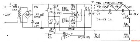
The high voltage D. C. regulated power supply introduced in the example has the simple circuit and high work efficiency and the output circuit voltage can be regulated constantly between 0-2V and it can be used as high voltage power of electronic components measure, science and education experiment.
Work's Principle of the Circuit
The high voltage D. C. regulated power supply circuit consists of mains input circuit,multivibrator type oscillator,voltage adjustment and stabilization circuit,voltage booster circuit and it is showed as the picture 5-35.The mains input circuit is composed of mains switch,S,fuse,FU,mains transformer,T,rectifier bridge,UR,voltage regulator diode,VS, and filter capacitor,C1.The multivibrator type oscillator circuit consists of operational amplifier IC(N1and N2),N1,resistor,R4-R7and capacitor,C3. (View)
View full Circuit Diagram | Comments | Reading(5491)
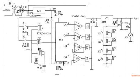
Numerical Control D. C. Regulated Power Supply Fifteen
Published:2011/6/2 12:07:00 Author:Michel | Keyword: Numerical Control, D. C., Regulated Power Supply, Fifteen
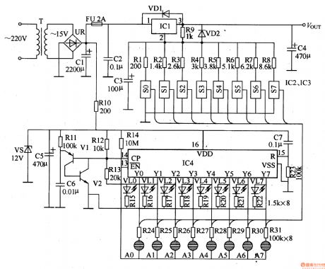
The numerical control D. C. power-supply circuits-fixed introduced in the example uses metal touch button ,digital IC and electron switch IC to converse the magnitude of output voltage.Compared to D. C. regualted power-supply cf traditional mechnical range switch,it has the advantage of lowbreakdown and convenient operation.
Work's Principle of the Circuit
The numerical control D. C. power-supply circuits-fixed is composed of mains circuit,free-running multivibrator,counting distributor,analog switching circuit and control circuit and it is showed as the picture 5-34.The mains circuit consists of mains transformer,T,rectifier bridge,UR,capacitor,C1-C5,resistor,R9,R10,diode,VD1,VD2,three-terminal integrated regulator,IC1 and zener diode,VS. (View)
View full Circuit Diagram | Comments | Reading(2004)
Bi-directional Thyristor-composed AC Voltage Regulation Circuit
Published:2011/5/17 8:07:00 Author:Joyce | Keyword: Bi-directional Thyristor-composed, AC, Voltage Regulation
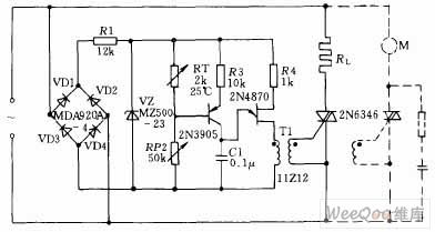
As shown in the graph below, the circuit uses to control heaterload RL (resistance wire). The trigger circuit uses UJT relaxation oscillators. It issupplied after the AC power supply is rectified via rectifier bridge and sliced into trapezoidal DC via resistance R1 and stabilivolt VZ .Output of SJU goes to the bi-directional thyristor door gate circuit after being coupled by pulse transformer. If you want to control the speed of DC motor M,you can connect the bi-directional thyristor and the motor in parallel according to the dotted line in the graph. In this way, it can absorb the overvoltage of the bidirectional thyristor, which is caused by the discharge of inductive load.
(View)
View full Circuit Diagram | Comments | Reading(885)
| Pages:216/291 At 20201202203204205206207208209210211212213214215216217218219220Under 20 |
Circuit Categories
power supply circuit
Amplifier Circuit
Basic Circuit
LED and Light Circuit
Sensor Circuit
Signal Processing
Electrical Equipment Circuit
Control Circuit
Remote Control Circuit
A/D-D/A Converter Circuit
Audio Circuit
Measuring and Test Circuit
Communication Circuit
Computer-Related Circuit
555 Circuit
Automotive Circuit
Repairing Circuit