
Index 207
Low voltage DC converter circuit
Published:2011/6/21 1:05:00 Author:Christina | Keyword: Low voltage, DC, converter
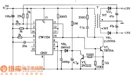
The low voltage DC converter circuit which is composed of the CW1524 is as shown in the figure. The secondary winding of the high frequency transformer T can be set according to the output voltage, the secondary winding of the figure has two groups of output: +15V and -15V.
The low voltage DC converter circuit which is composed of the CW1524 (View)
View full Circuit Diagram | Comments | Reading(852)
The positive-passive symmetric dual power supply circuit with only five elements
Published:2011/6/24 7:37:00 Author:Seven | Keyword: symmetric, power supply
In imported electric apparatus, we often see the figured passive/positive power supply circuit which provides with power for the power amplifier integrated circuit. Its features are as follows: 1. It's easy to make or select the power supply transformer whose secondary coils needn't central heads; 2.The passive/positive power supply is symmetric. 3.The efficiency of the power is high. 4.the structure is simple. The practice proves that on the premise that the power supply transformer has enough volume, it can approximately increase the volume of the capacitance and the turns of the transformer secondary coils, and the circuit is also used in low power audio power amplifier as the positive/passive symmetric dual power supply.
(View)
View full Circuit Diagram | Comments | Reading(1213)
Adjustable switch type voltage stabilizer circuit composed of the LM2577
Published:2011/6/21 1:18:00 Author:Christina | Keyword: Adjustable switch type, voltage stabilizer
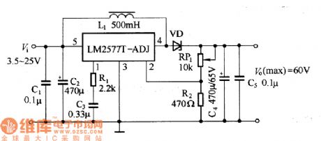
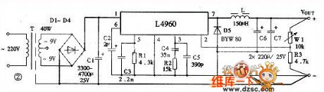
The switch type voltage stabilizer circuit which is composed of the LM2577 is as shown in the figure.
The adjustable switch type voltage stabilizer is composed of the LM2577.
(View)
View full Circuit Diagram | Comments | Reading(10438)
The single/dual power supply converter circuit
Published:2011/6/23 21:55:00 Author:Seven | Keyword: power supply, converter
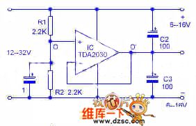
TDA2030 is an efficient computing amplifier. With its complementary input stage, we can convert the single pole power supply into two dual pole power supplies that the low-power circuits need.
In the circuit, the resistors of R1 and R2 with the same resistance compose a voltage distributor which makes the upper and lower part have the same voltage. The central point of the distributor is connected with the non-inverting phase input terminal of the amplifier, and the op-amp is assembled into a voltage follower which makes the LEV of O' and O terminal the same. And O' is a vain point, so it has to be separated from the power supply.
(View)
View full Circuit Diagram | Comments | Reading(3958)
0~30V continuous adjustable voltage stabilizer circuit
Published:2011/6/23 7:29:00 Author:Christina | Keyword: 0~30V, continuous, adjustable, voltage stabilizer
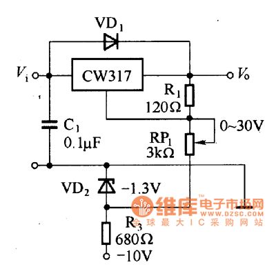
The 0~30V continuous adjustable voltage stabilizer circuit is as shown in the figure. In the figure, the RP1 is not connected with the ground directly, but it is connected with the potential which is lower than -1.25V. The R3 and VD2 of the circuit supply the -1.3V negative voltage reference, so the circuit can continuously adjust from 0V.
0~30V continuous adjustable voltage stabilizer circuit (View)
View full Circuit Diagram | Comments | Reading(699)
single-stage charging incentive-type PFC converter circuit
Published:2011/6/25 10:35:00 Author:John | Keyword: converter
View full Circuit Diagram | Comments | Reading(821)
Full-bridge single-stage PFC converter circuit
Published:2011/6/25 10:31:00 Author:John | Keyword: PFC converter
View full Circuit Diagram | Comments | Reading(871)
The auto regulated reversible power supply circuit
Published:2011/6/24 3:18:00 Author:Seven | Keyword: auto regulated, reversible, power supply
View full Circuit Diagram | Comments | Reading(859)
The AC regulator circuit of the dual-way controllable silicon
Published:2011/6/24 3:40:00 Author:Seven | Keyword: AC regulator, controllable silicon
View full Circuit Diagram | Comments | Reading(860)
The transistor communicaiton transformer circuit
Published:2011/6/23 22:24:00 Author:Seven | Keyword: transistor, communicaiton transformer
View full Circuit Diagram | Comments | Reading(774)
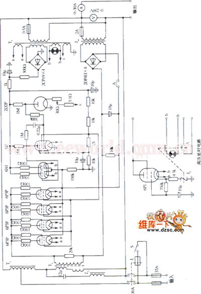
The 614-C2(5kVA)AC voltage stabilizer circuit
Published:2011/6/24 3:30:00 Author:Seven | Keyword: voltage stabilizer
View full Circuit Diagram | Comments | Reading(2759)
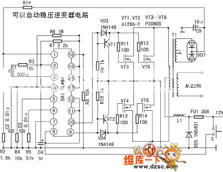
The self-steady reverser circuit
Published:2011/6/24 3:35:00 Author:Seven | Keyword: self-steady reverser
The self-steady reverser circuit is shown as above.
(View)
View full Circuit Diagram | Comments | Reading(683)
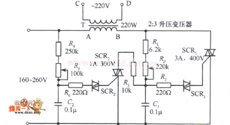
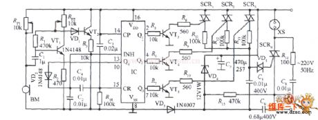
The audio controlled AC regulator circuit
Published:2011/6/24 3:56:00 Author:Seven | Keyword: audio controlled, AC regulator
View full Circuit Diagram | Comments | Reading(750)
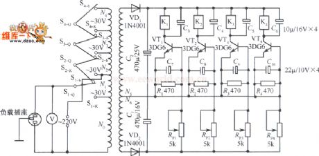
The 5-12V continuous and adjustable regulated power supply circuit
Published:2011/6/24 7:10:00 Author:Seven | Keyword: regulated, power supply
View full Circuit Diagram | Comments | Reading(788)
Voltage stabilizer circuit outputs the positive and negative voltage simultaneously
Published:2011/6/23 8:06:00 Author:Christina | Keyword: Voltage stabilizer, positive, negative, simultaneously
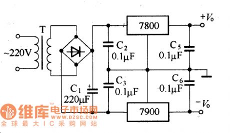
Some circuits need the voltage source that can output the positive and negative voltage simultaneously, we can form the voltage stabilizer circuit that outputs the positive and negative voltage simultaneously by using the CW7800 series and CW7900 series integrated voltage stabilizers. The circuit is as shown in the figure.
Voltage stabilizer circuit outputs the positive and negative voltage simultaneously
Because this circuits use the same group of rectifier circuit, so the circuit is simple. But it is not suitable for the two-way unbalanced load circuit, otherwise it will result in the increasing of the output voltage error to destroy the stability. (View)
View full Circuit Diagram | Comments | Reading(1597)
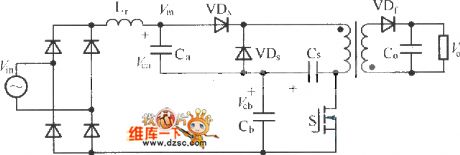
Boost Flyback-type single-stage isolated PFC converter circuit
Published:2011/6/25 9:40:00 Author:John | Keyword: converter
View full Circuit Diagram | Comments | Reading(1431)
Basic Boost single-stage isolated PFC converter circuit
Published:2011/6/25 6:08:00 Author:John | Keyword: converter
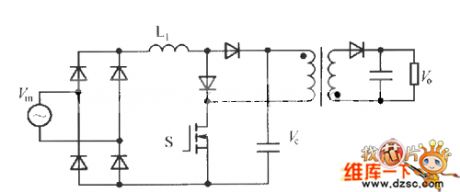
View full Circuit Diagram | Comments | Reading(1299)
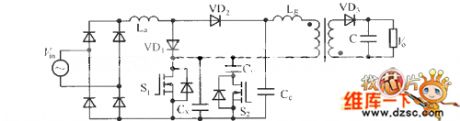
single-stage full-bridge PFC converter circuit
Published:2011/6/25 6:04:00 Author:John | Keyword: converter
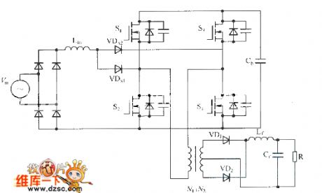
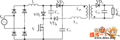
PFC technology has been gradually integrated into a lot of good converter circuits. The new developed structures can well suppress power supply to input harmonics, regulating the input current’s waveform. They also have excellent output characteristics, fully achieving the advantages of PFC circuit and power conversion circuit. The figure shows the single-stage PFC circuit formed by the Boost circuit and full-bridge converter. As for practical applications, the synthesis circuit improves the charging and discharging circuit of VDx1 and VDx2, thus leading to better functions.
(View)
View full Circuit Diagram | Comments | Reading(2565)
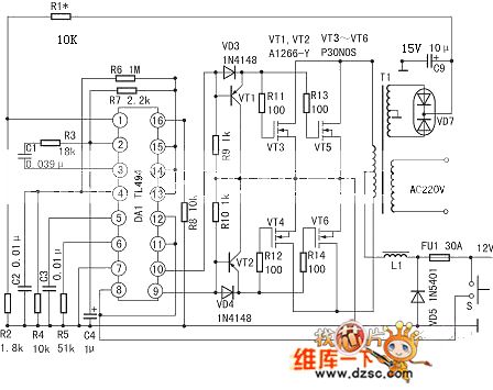
The VMOS pipe switch regulated power supply circuit
Published:2011/6/23 6:38:00 Author:qqtang | Keyword: VMOS, switch, power supply
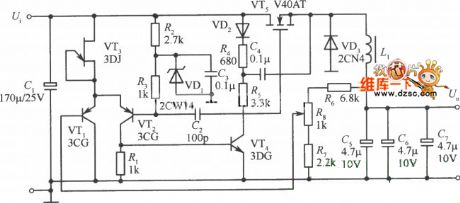
In the circuit is another VMOS pipe switch regulated power supply circuit. As the circuit is fixed with the voltage comparator 710, so this circuit is simpler than the former one. In the circuit, the resistors (R1, R2 and R3) and the stabilivolts(VD1 and VD2) compose the voltage distribution circuit, the 28V voltage is split into the voltages of 5v, 6v and 18v as the power supply of 710; the resistors(R12 and R13), capacitors C13, diodes(VD6 and VD7) and transistor VT3 compose the power supply soft starting circuit. At the moment of power-on, the starting circuit can make the VT1 drive pulse width of VMOS pipe increase the in index patten.
(View)
View full Circuit Diagram | Comments | Reading(662)
An air-conditioner mainboard circuit
Published:2011/6/19 20:35:00 Author:qqtang | Keyword: air-conditioner, mainboard
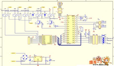
View full Circuit Diagram | Comments | Reading(1016)
| Pages:207/291 At 20201202203204205206207208209210211212213214215216217218219220Under 20 |
Circuit Categories
power supply circuit
Amplifier Circuit
Basic Circuit
LED and Light Circuit
Sensor Circuit
Signal Processing
Electrical Equipment Circuit
Control Circuit
Remote Control Circuit
A/D-D/A Converter Circuit
Audio Circuit
Measuring and Test Circuit
Communication Circuit
Computer-Related Circuit
555 Circuit
Automotive Circuit
Repairing Circuit