
Remote Control Circuit
Index 7
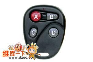
The remote control TX4004
Published:2011/8/4 0:51:00 Author:Seven | Keyword: remote control

Code type: encode/decode PT2260/PT2262 (weld plate); study code eV1527/PT2240B; roll code HCS101/HCS301;
The features of the product:
Low price, small-sized emitter handle, fine outline, energy-saveing, reliable working, black surface. The symbol of the rubber cushion can be set according to the need.
Application range:
Motor alarm product, car alarm product, domestic alarm product, short-distance wireless control product, remote control garage door, remote control electric curtain door/window, collapsible door, remote control sliding gate and industrial control, etc. (View)
View full Circuit Diagram | Comments | Reading(1485)
The remote control TX1004
Published:2011/8/4 1:00:00 Author:Seven | Keyword: remote control
Code type: encode/decode PT2260/PT2262 (weld plate); study code eV1527/PT2240B; roll code HCS101/HCS301; The features of the product:Low price, small-sized emitter handle, fine outline, energy-saveing, reliable working, black surface. The symbol of the rubber cushion can be set according to the need.Application range:Motor alarm product, car alarm product, domestic alarm product, short-distance wireless control product, remote control garage door, remote control electric curtain door/window, collapsible door, remote control sliding gate and industrial control, etc. (View)
View full Circuit Diagram | Comments | Reading(1317)
Electric fan infrared remote control circuit (6)
Published:2011/8/11 19:45:00 Author:TaoXi | Keyword: Electric fan, infrared, remote control
infrared transmitter
(View)
View full Circuit Diagram | Comments | Reading(1358)
Electric fan infrared remote control device
Published:2011/8/11 20:10:00 Author:TaoXi | Keyword: Electric fan, infrared, remote control device
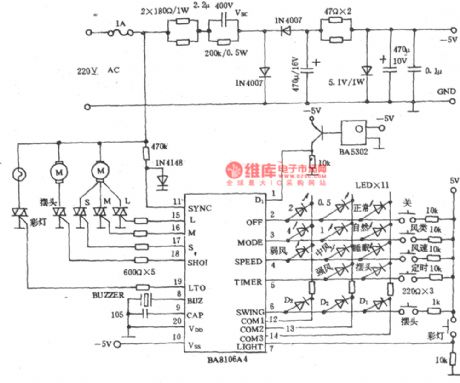
Emitter:
Receiver:
(View)
View full Circuit Diagram | Comments | Reading(1225)
The circuit diagram of using TV remote controller to cut off household appliance power supply
Published:2011/8/11 6:24:00 Author:nelly | Keyword: TV remote controller, household appliance, power supply
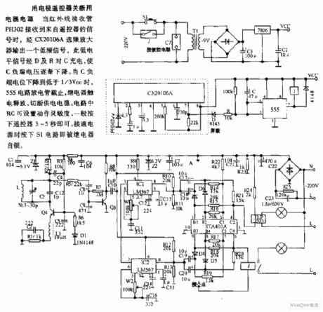
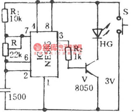
Using TV remote controller to cut off the household appliance power supply. When the infrared light-receiving diode PH302 receives the remote controller's signal, a low frequency signal is outputed by CX20106A frequency selective amplifier, this low level signal charges to C by D and R, C's negative terminal voltage drops. When it drops to lower than 1/3 VCC, the 555 circuit discharge tube is turned off, the relay is electric shocked and released, the power supply is cut off. In the circuit, RC can set action sensitivity by pressing remote controller for 3~5s. When the power supply turns on, pressing S1 circuit, then the relay is self-locking.
(View)
View full Circuit Diagram | Comments | Reading(1875)
Four channels infrared remote controller circuit diagram
Published:2011/8/11 5:57:00 Author:nelly | Keyword: Four channels, infrared remote controller
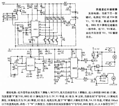
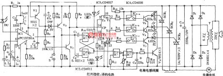
The receiving circuit: the infrared signal is inputed to MC3373 from 7 foot by phototube, the amplified signal outputs from 1 foot, it is transported into the 12 foot of decoder 8802. When the transmitter F is pressed, the voltage of 8802's 11 foot up to 2.5V, V1 turns on, K1 pulls in, M is forward rotation. When it receives B signal, 11 foot's voltage drops, 18 foot's voltage up to 5V, K1 releases, K2 pulls in, the motor is reversal rotation. Pressing W , 9 foot's voltage rises, V4, V5 turn on, it can drive the DC motors which under 100mA, pressing W again, 9 foot resets. When the receiver receives the transmitter's S signal, 8802 resets, 8, 9 feet are all 0V.
(View)
View full Circuit Diagram | Comments | Reading(2198)
The reporting timing contact printer circuit
Published:2011/8/15 22:15:00 Author: | Keyword: contact printer
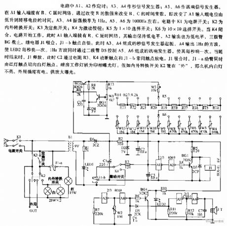
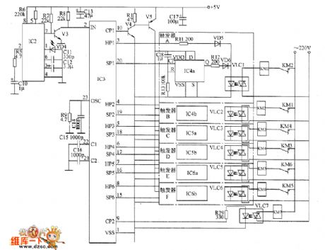
In the circuit, A1 and A2 are the timers; A3 and A4 are the second signal generators; A5 and A6 are the sound signal generator. At the input terminal of A1, the R and C time delay net is connected there, by changing the value of R, the time constants of R and C are changed, i.e the time of A1 input terminal LEV rising from low to transfer potential is changed. The oscillating frequency of A3 and A4 is 1Hz, the frequency of A5 and A6 is 1000Hz or so. In the circuit, K1 is the power supply switch; k2 is the in-out converting switch; K3 is the focus switch; K4 is the jogging switch; K6 is the 10*10 selecting switch.
(View)
View full Circuit Diagram | Comments | Reading(1004)
The dark room timer circuit
Published:2011/8/15 22:24:00 Author: | Keyword: dark room timer
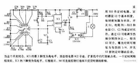
The 555 is the timing circuit, the timer has 12 basic marks, each interval is half-gear. The switch S1, resistors R1-R12 and capacitors C1 and C2 compose the timing component, the adjusting gear can be divided into 1/4 by C2, i.e when S2 is closed, the exposing time is reduced to 1/4 gear. The switch S3 controls the starting of the timer. When the switch is closed, the 3-pin of IC1 is turned into a high LEV, the solid relay IC2 is conducting, the bulb in the shadow amplifier is lighted.
(View)
View full Circuit Diagram | Comments | Reading(1593)
Remote control electric hoist control circuit diagram 1
Published:2011/8/15 22:01:00 Author:Ecco | Keyword: Remote control , electric hoist control
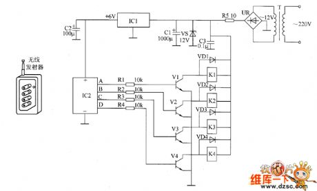
The remote control electric hoist control circuit consists of the wireless transmitter, wireless receiver control circuit and the main control circuit. Wireless transmitter uses TWH9326 four key BP transmitter. Wireless receiver control circuit consists of the power supply circuit, wireless receiver integrated circuit IC2 and control implementation circuit, and it is shown in Figure 1. Control implementation circuit consists of the resistors R1 ~ M, transistors V1 ~ V4, diodes VDi ~ VD4 and relays K1 ~ D4. R1 ~ R4 select the 1/4W metal film resistors; R5 selects the 2V metal film resistor.
(View)
View full Circuit Diagram | Comments | Reading(7897)
Remote control electric hoist control circuit diagram 2
Published:2011/8/15 22:07:00 Author:Ecco | Keyword: Remote control, electric hoist control
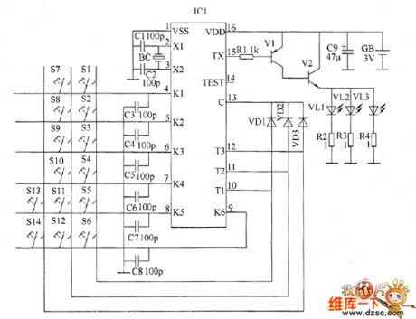
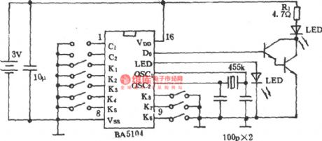
The remote control electric hoist control circuit consists of the infrared transmitter and infrared receiver control circuit. Infrared transmitter circuit is composed of the infrared emission coding circuit and peripheral components of integrated circuit ICI, and it is shown in Figure 1. Control buttons S1 ~ S4, diodes VD1 ~ VD3, capacitors C3 ~ C8 and IC1's pin 4 to 13 internal circuit form the keying input circuit; capacitors C1 and C2, quartz crystal oscillator BC and IC1'S pin 2,3 internal circuit form the oscillator circuit; resistors RI ~ M, transistors VI and infrared light-emitting diodes VL1 ~ VL3 and IC1's pin 15 internal circuit form the infrared driver circuit.
(View)
View full Circuit Diagram | Comments | Reading(3201)
timer circuit fixing preset time
Published:2011/7/27 8:25:00 Author:Fiona | Keyword: Fixing preset time, timer
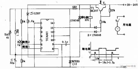
The 13 pin between Threshold value 1 and 2 absorbs the transistor's base current. If relay releases,it starts the switch process again through pressing the button after restoring time 0.5 S.Window discriminator TCA965 can constitute a timer.Capacity C which decides the time charges after pressing the button Ta ,transistor T1 gets the base current from TCA965's 2 pin,power supplys current.Rectification process times 10 S in advance.In some period indicator light LD57 is bright. When capacitor's charging voltage exceeds threshold value 1 ,the relay is closed.But when capacitor's charging voltage exceeds threshold value 2 after rectifying by potentiometer RP,the relay releases again. Relay's pick-up duration can be adjusted in 0 ~ 18 S.
(View)
View full Circuit Diagram | Comments | Reading(2083)
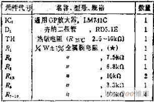
Simplified bridge type thermosensitive temperature measurement circuit
Published:2011/7/27 8:21:00 Author:Fiona | Keyword: Simplified bridge type, thermosensitive temperature measurement
Circuit Work
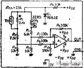
Four-leg resistors are equal, this is the most common method that the bridge circuit selects parameters,each leg of the circuit resistance takes 10K. VR1 is a variable resistor, and itsfunction is to make the output voltagebe 0 at the required temperature, when the thermistor resistance and the arm resistance are equal, adjust VR1 so that the bridge is balance.
Thermistor resistance falls due to temperature rises, the differential amplifier output will rise, the output voltage depends on the thermistor constant B or increasing the voltage at the bridge. (View)
View full Circuit Diagram | Comments | Reading(1078)
The infrared remote control music socket circuit (1)
Published:2011/8/1 22:07:00 Author:TaoXi | Keyword: Infrared remote control, music socket
The infrared remote control music socket circuit is as shown, it is composed of the pulse oscillator circuit , the buffer stage and the driver stage.
Infrared receiving controller circuit:
(View)
View full Circuit Diagram | Comments | Reading(986)
The infrared remote control music socket circuit (2) PH303A
Published:2011/8/1 22:07:00 Author:TaoXi | Keyword: Infrared remote control, music socket circuit
The PH303A×2 infrared pulse transmitter circuit is as shown, by adjusting the RP1 you can make the oscillation frequency to12kHz.
Infrared remote control receiver circuit:
(View)
View full Circuit Diagram | Comments | Reading(918)
The roll-pattern type wireless remote control circuits TH150/TH150A/TH150B
Published:2011/8/1 22:06:00 Author:TaoXi | Keyword: Roll-pattern, wireless remote control
The internal structure of the roll-pattern type wireless remote control circuit is very complex, the coding method is also very special, but the usage of this circuit is the same as the digital coding circuit, even more simple. The radio control circuit which is composed of the rolling code decoding circuits TH150/TH151A/TH151B. The radio transmission circuit(it is composed of the rolling code circuit, the TH150 and the transistor carrier frequency oscillator):
The super-regenerative wireless remote control receiver circuit (which is composed of the TH151A/B rolling decoding circuit):
(View)
View full Circuit Diagram | Comments | Reading(927)
The game infrared remote control circuit
Published:2011/8/1 22:06:00 Author:TaoXi | Keyword: Game, remote control circuit
Game infrared remote control circuit
(View)
View full Circuit Diagram | Comments | Reading(1043)
The single-channel wireless remote control switches TDC1808/TDC1809
Published:2011/8/1 22:06:00 Author:TaoXi | Keyword: Single-channel, wireless remote control switch
The transmitter of the three-way wireless remote control switch is as shown, the receiving circuit is the same to the single channel circuit.
(View)
View full Circuit Diagram | Comments | Reading(1009)
The key-buckle type wireless encoding remote controller circuit 1
Published:2011/8/1 22:10:00 Author:TaoXi | Keyword: Key-buckle type, wireless encoding, remote controller
Key-buckle type wireless encoding remote controller circuit 1
(View)
View full Circuit Diagram | Comments | Reading(928)
The key-buckle type wireless encoding remote controller circuit (2)
Published:2011/8/1 22:10:00 Author:TaoXi | Keyword: Key-buckle type, wireless encoding, remote controller
Key-buckle type wireless encoding remote controller circuit 2
(View)
View full Circuit Diagram | Comments | Reading(890)
The crane wireless remote control circuit SF05B/SJ05C
Published:2011/8/1 22:09:00 Author:TaoXi | Keyword: Crane, wireless remote control
Figure (a) is the radio transmission circuit:
Figure (b) is the remote control receiving and control circuit:
(View)
View full Circuit Diagram | Comments | Reading(1071)
| Pages:7/34 1234567891011121314151617181920Under 20 |
Circuit Categories
power supply circuit
Amplifier Circuit
Basic Circuit
LED and Light Circuit
Sensor Circuit
Signal Processing
Electrical Equipment Circuit
Control Circuit
Remote Control Circuit
A/D-D/A Converter Circuit
Audio Circuit
Measuring and Test Circuit
Communication Circuit
Computer-Related Circuit
555 Circuit
Automotive Circuit
Repairing Circuit