
Remote Control Circuit
Index 11
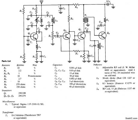
27255_MC_TD_CRYSTAL_TRANSMITTER
Published:2009/7/23 21:41:00 Author:Jessie
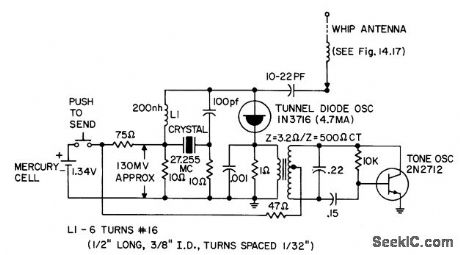
Silicon-transistor Hartley oscillator modulates tunnel-diode oscillator in remote-control transmitter,- Transistor Manual, Seventh Edition General Electric co., 1964, p 356. (View)
View full Circuit Diagram | Comments | Reading(1890)
CARRIER_CURRENT_TV_CONTROL
Published:2009/7/23 21:40:00 Author:Jessie
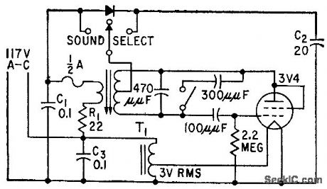
Low-power oscillator provides both unmodulated and 60-cps modulated signals for power-line carrier. current transmission to control receiver in tv set. Unmodulated carrier having preset duration controls channel selection, while modulated carrier controls sound level. System operates on one of four nonadjacent frequencies (52.5, 57.5, 67.5, and 73.5 kc) to ovoid interaction between nearby systems,-J. R. Banker and C. H. Wood, Jr., Line Current Controls Remote Tv Receiver, Electronics, 31:33, p 68-69. (View)
View full Circuit Diagram | Comments | Reading(1224)
TV_STATION_CONTROL
Published:2009/7/23 21:46:00 Author:Jessie
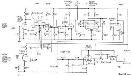
Control pulses transmitted in blanking interval by tv network transmitter are decoded by receiver circuits shown and translated into six different switching actions used to introduce special program matter such as commercials, weather reports, and local film projector material that may be different for each network station.-K. Kazama and T. Ishino, Remote Tv Control by Blanking-Interval Pulses, Electronics, 33:20, p 79-81. (View)
View full Circuit Diagram | Comments | Reading(1684)
27255_MC_REMOTE_CONTROL_RECEIVER
Published:2009/7/23 21:45:00 Author:Jessie
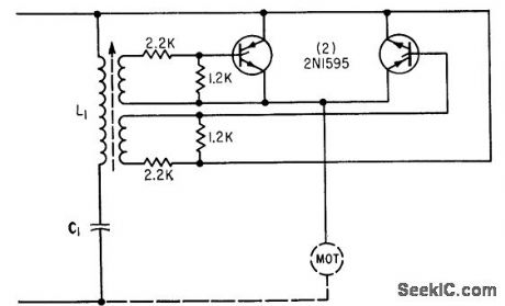
Output of superregenerative detector consists of 200-kc quench signal and 1,000-cps tone modulation from incoming signal. Quench fiber passes only audio signal to amplifier.Amplified audio is detected and resulting direct current used to operate relay K1.-Texcts Instruments Inc., Transistor Circuit Design, McGraw-Hill, N.Y., 1963, p 363. (View)
View full Circuit Diagram | Comments | Reading(2124)
Precious cultural relics radio pursuit device circuit
Published:2011/7/26 3:13:00 Author:Christina | Keyword: Precious, cultural relics, radio pursuit device
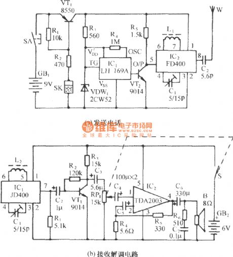
The circuit is as shown in the figure. It is composed of the vibration type wireless voice launch circuit, the wireless receiving and demodulation circuit. If you put the transmitter circuit board in the protected cultural relic, when someone moves the historical relic, the press type switch SA will reset, at the same time, the mercury switch SK conducts because of the moving, the VT1 conducts, the sound circuit and the wireless launch circuit get power to send out the voice alarm circuit. When the wireless receiving and demodulation circuit receives the alarm circuit, it will send out the sound of catch the thief! and you can track the thief.
(View)
View full Circuit Diagram | Comments | Reading(981)
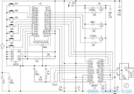
High reliability remote control circuit composed of the monolithic wireless transceiver integrated chip NRF401
Published:2011/7/31 22:17:00 Author:Christina | Keyword: High reliability, remote control, monolithic, wireless transceiver, integrated chip
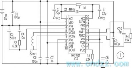
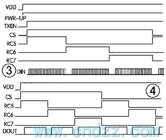
The NRF401 is designed as one kind of digital frequency band 433MHz monolithic wireless transceiver integrated chip which is produced by the Nordic company. This IC has the functions of high-frequency transmitter, high-frequency receiver, PLL synthesizer, FSK modulation, FSK demodulator and multi-channel switch functions.
The circuit is as shown in figure 2. This circuit is the transmitter circuit and the receivier circuit. The SCM IC2 PIC16C57 controls the sending & receiving state and the decoding & coding of the NRF401. When you press the button, the IC2 receives the low level signal, and the pin of IC2 outputs the high level to the pin of IC1 to make the NRF401 get into the launch state. At the same time, this device chooses the different crystals randomly, and it makes the transmitting frequency jump between the six frequency points 432.84MHz, 433.25MHz, 433.92MHz, 434.33MHz, 435.01MHz, 435.42MHz.
(View)
View full Circuit Diagram | Comments | Reading(2315)
Infrared remote control power socket circuit
Published:2011/7/31 22:35:00 Author:Christina | Keyword: Infrared, remote control, power socket
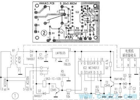
The socket circuit is as shown in figure 1. This circuit uses the receiving, amplification, demodulation integrated infrared receiver, the relay triggers the driving circuit to use one piece of dual D flip-flop MC14013, this circuit uses only one channel of it to connect into the bistable form, the D is connected with the Q, the R and S port are connected with the ground. The R3 and C2 RC networks which are connected with the R port have the power-on reset function, so when the power failure comes again, the socket is in the off state.
In peacetime, the receiving head output port has the 4.2V high level, T2 is in the conduction state, the bistable circuit trigger input port has the low level, the Q port outputs the low level, T1 cuts off, the relay J stops operating, the socket has no 220V output power. If you press the remote controller again, the receiving head will receive the signal of remote controller, and the output port will output the demodulated pulse signal, so the voltage of the output port reduces, the T2 cuts off, the socket losses the power again.
(View)
View full Circuit Diagram | Comments | Reading(2456)
The remote control circuit of the toy car
Published:2011/8/1 0:53:00 Author:Christina | Keyword: remote control, toy car
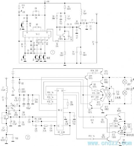
Figure 1 is the remote control circuit, when the control pin of this circuit is connected with the ground, the function which is corresponding to this pin will be in the selective passing state, and it is latched by the latch circuit, the latch signal controls the coding circuit to produce the coded signal that is corresponding to the control function. The carrier signal which is produced by the Q2 and XT is modulated by the coded signal and amplifierd by the Q1. R7 is the oscillation resistance of TX-2, LED is the power supply launch indicator light of the LED.
Figure 2 is the receiving circuit, the high frequency signal which is output by the transmitter is received by the receiving antenna, the super-regenerative receiver circuit is composed of the Q1, L2, C2, C3, the parallel resonant circuit is composed of the L2 and C2, the function of the parallel resonant circuit is frequency selection, C3 is the super-regenerative positive feedback capacitor.
(View)
View full Circuit Diagram | Comments | Reading(4258)
One kind of wireless remote control circuit
Published:2011/8/1 1:12:00 Author:Christina | Keyword: wireless, remote control
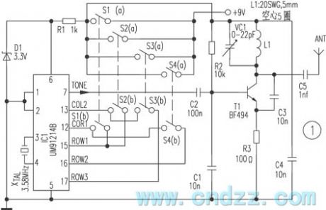
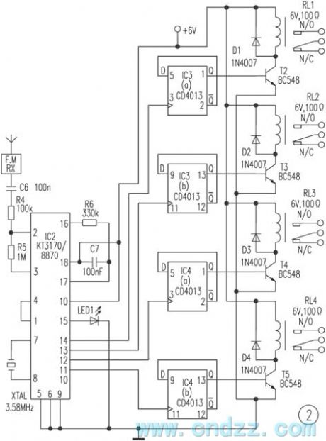
The remote control transmitter is composed of the DTMF generator and the FM transmitter circuit. Here we use one piece of UM91214B phone specific IC to produce the DTMF signal, the 3V power supply voltage is supplied by the 3V zener tube D1.
The transmitter circuit is composed of the transistor T1 and the external circuits, the tuning circuit L1 and VC1 is tuned at the 100MHz carrier frequency, the antenna uses the whip shape antenna, the length is 10-15cm, the control range is wide. The DTMF signal is sent into the base electrode of T1 through the IC1, and it is output through the antenna ANT.
The receiving part is composed of the DTMF/BCD transform chip IC2 and a group of four trigger latch circuits IC4, IC3. The FM DTMF signal is demodulated by the receiver to change into the BCD signal. At this time the numerical code 1 is the 0001, the numerical code 4 is the 0100.
(View)
View full Circuit Diagram | Comments | Reading(3330)
Audio volume remote control circuit
Published:2011/8/1 1:24:00 Author:Christina | Keyword: Audio volume, remote control
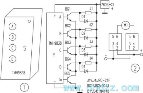
Operating principle: the circuit is as shown in the figure, S is the 4-bit wireless remote control transmitter, Y is the receiving module which is matching with the transmitter. The output ports of Y are amplified by the BG1 ~ BG5 to change the four channels of interlock data control output port signal into the non-latching form, and it controls the electric motor through the relays J1-J4. The M1 controls the main volume, the M2 controls the high and low tones. As the figure 1 shows, the circuit of the electric motors M1 and M2 are the same, also the operating principles. When you press the A button of the transmitter S, the output ports A and I0 of Y output the high level, the BG1 and BG5 conduct. J1 closes, M1 gets power to operate, if you loosen the button, the output of I0 disappears, the electric motor M1 releases to stop working.
(View)
View full Circuit Diagram | Comments | Reading(1521)
Homemade wireless remote control intermediate frequency switcher circuit
Published:2011/7/26 2:05:00 Author:Christina | Keyword: Homemade, wireless, remote control, intermediate frequency, switcher circuit
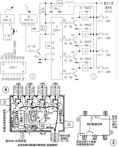
Operating principle: the principle diagram of the wireless medium frequency switcher is as shown in figure 1. A1 is the wireless remote control dedicated transmitter module, when you press the switch S to connect the power, the built-in transmitting antenna sends the 280MHz ~ 300MHz ultra-high frequency modulation electromagnetic wave to the surrounding space, it is received by the built-in receiving antenna of the dedicated receiver module A2 in the effective distance, then it is modulated, amplified, detected, transformed by the A2 module, the output port outputs the high level pulse to conduct VT5 and control the operating of IC.
(View)
View full Circuit Diagram | Comments | Reading(1950)
Intelligent wireless security system design circuit
Published:2011/7/26 1:52:00 Author:Christina | Keyword: Intelligent, wireless, security system, design circuit
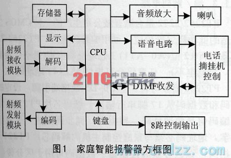
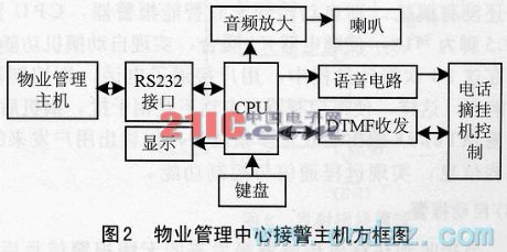
The intelligent wireless security system is composed of the sensor, the family intelligent alarm, the property management center alarm-receiving host computer and the related control management softwares. Figure 1 is the block diagram of the family intelligent alarm, figure is the block diagram of the property management center alarm-receiving host computer.
1.1 The host computer circuit
As the figure 1 shows, the RF receiving module of the host computer circuit receives the alarm signal of the sensor, and alarm signal is decoded by the decoder (PT2272), so we get the address and data type of the alarm sensor, only when the host computer address and the sensor address are the same, the signal can be received by the host computer.
(View)
View full Circuit Diagram | Comments | Reading(2473)
Intelligent infrared remote control circuit design
Published:2011/7/26 1:36:00 Author:Christina | Keyword: Intelligent, infrared, remote control, design
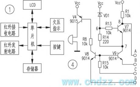

The structure of the intelligent infrared remote controller is as shown in figure 1, this device is composed of the single-chip microcomputer, the infrared receiving part, the display circuit, the memory, the button and undervoltage indication circuit. This circuit can be driven by two batteries. The single-chip microcomputer uses the infrared remote control transmitter chip BA5048, the operating power voltage is 1.5-5V. The memory, LCD and the infrared emitter all have the ready-made 3V voltage products, the common infrared receiver IC (such as the CX20106, HS0038) has the rated operating voltage of 5V, it is hard to find the low voltage infrared receiver.
(View)
View full Circuit Diagram | Comments | Reading(1429)
HT6337 (electric fan) infrared remote control receiving decoder circuit
Published:2011/8/1 3:42:00 Author:Christina | Keyword: electric fan, infrared, remote control, receiving, decoder
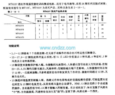
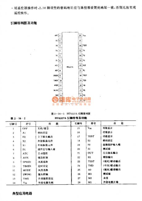
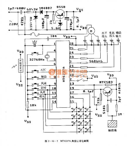
The HT6337 is designed as one kind of infrared remote control receiving decoder circuit that can be used in the electric fan application. It uses the 28-pin dual-row DIP package, the matching model is HT12C. The HT6337 is one of the series products. The features of it are as shown in table 2-16-1.
The pin-1, pin-7 - pin-12 have the function buttons.The array display system is composed of the 15-17,9-12 pins, and the system uses 11 LEDs to display three kinds of wind velocities, four kinds of timings, three kinds of wind types and the automatic room temperature control.The 19-pin has the contact protection input port.The 13-pin is the environmental temperature control input port. The room temperature detection sensor is composed of the thermal components and the capacitances, it can change the temperature variation into the current variation of pin-13.
(View)
View full Circuit Diagram | Comments | Reading(3614)
HD44043 (TV) infrared remote control receiving decoder circuit
Published:2011/8/1 3:22:00 Author:Christina | Keyword: TV, infrared, remote control, receiving, decoder circuit
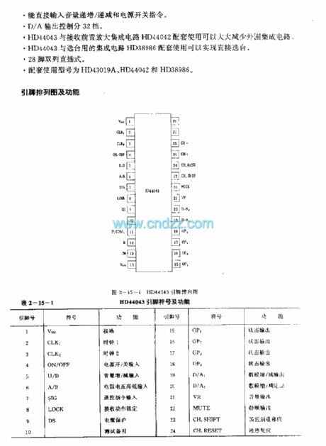
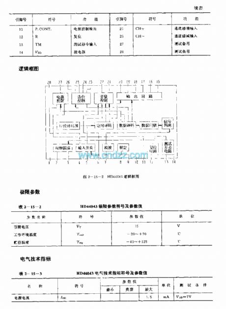
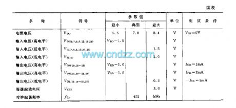
The HD44043 is designed as one kind of infrared remote control receiving decoder circuit that can be used in the TV application. The internal circuit is composed of the wave-detector, the signal discrimination circuit, the data decoding circuit, the timing decoding circuit, the channel-selection controller, the oscillator, the reset circuit and the output circuit.
Features
It uses the CMOS technology.Low power consumption, the typical value is 5.5mW.It can receive 31 kinds of instructions.It can input the volume up/down and the power switching instructions directly.The D/A output control has 32 stages.The HD44043 can be used with the preamplifier integrated circuit HD44042 to reduce the peripheral ICs.The HD44043 can be used with the channel-selection IC HD38986 to select the channel directly.
(View)
View full Circuit Diagram | Comments | Reading(1279)
PT2275 general infrared remote control decoder circuit
Published:2011/8/1 2:46:00 Author:Christina | Keyword: general, infrared, remote control, decoder
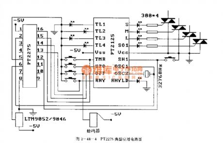
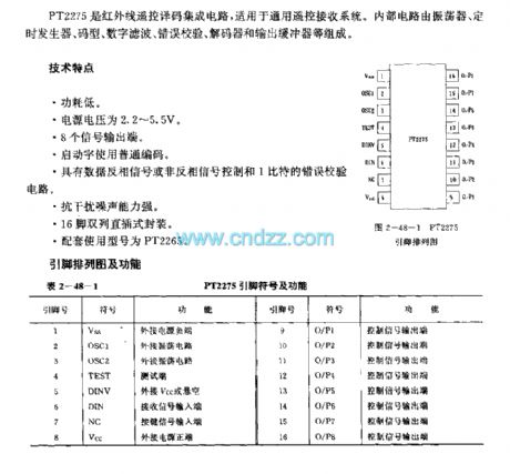
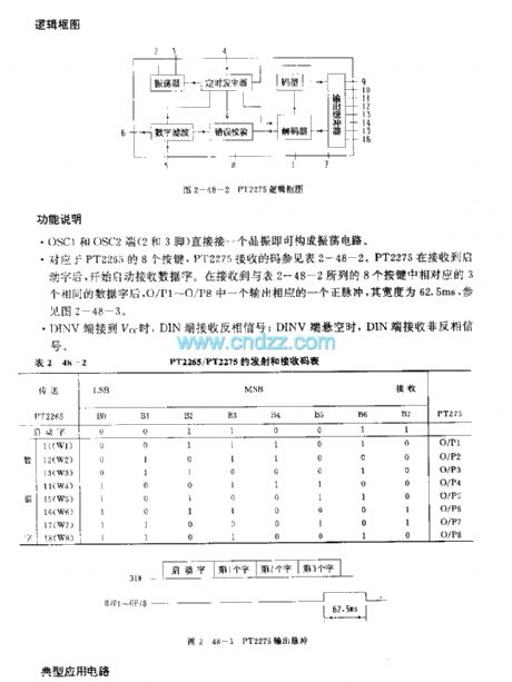
The PT2275 is designed as one kind of general infrared remote control decoder circuit that can be used in the gernal remote control receiving systems. The internal circuit is composed of the oscillator, the timing generator, the code type digital filter, the error checker, the decoder and the output buffer.etc.
Features
Low power consumption.The power supply voltage is 2.2-5.5V.It has eight signal output ports.The start field uses the ordinary code.It has the data inverted signal or non-inverting signal control function and the 1-bit error checking circuit.It has strong anti-interference ability.16-pin dual-row DIP package.The matching model is PT2265.
(View)
View full Circuit Diagram | Comments | Reading(2680)
16-channel remote control circuit (T998C)
Published:2011/8/1 2:25:00 Author:Christina | Keyword: 16-channel, remote control
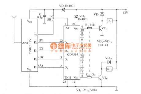
As the figure shows, the 16-channel remote control circuit (T998C) is composed of the T998C-12 V receiving module and the four-sixteen-channel decoder CD4514. This circuit can be used as the latched output and the unlatched output, the SB is the switch. When the SB is connected with the VDD, the circuit is in the latched output state, the sixteem output ports are not controlled by the Io output state; when the SB is connected with the Io output port, the circuit is in the unlatched output state, the sixteem output ports are controlled by the Io output state.
When you are using this 16-channel remote control receiving circuit, you must follow the binary-decimal encoding mode to code, and you also need to follow the coding table.
(View)
View full Circuit Diagram | Comments | Reading(3937)
Remote control circuit composed of the TWH9236/9238 miniature radio-controlled component
Published:2011/8/1 2:15:00 Author:Christina | Keyword: Remote control circuit, miniature radio-controlled component
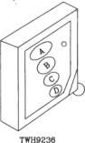
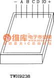
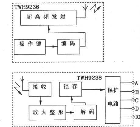

The TWH9236/9238 miniature radio remote control transmitting/receiving component contains a key chain type transmitter and a miniature receiver.
For the launch component TWH9236, the operating voltage is supplied by a Az3 type button cell, the voltage is 1.5V, the operating current is smaller than 6mA. But the operating voltage of the receiving component TWH9238 is 6V, the static current is only 1.5mA. The output voltage of the data output port is 5V, the maximum output current is 1.8mA, so it can drive the transistor directly. The remote control distance is more than 50m.
The TWH9238 can form the 3 and 4-channel remote control transmitting/receiving circuits, also it can be expanded to the 9 and 16-channel remote control circuit.
(View)
View full Circuit Diagram | Comments | Reading(1562)
LOW_POWER_REGULATOR_REFERENCE
Published:2009/7/1 2:11:00 Author:May
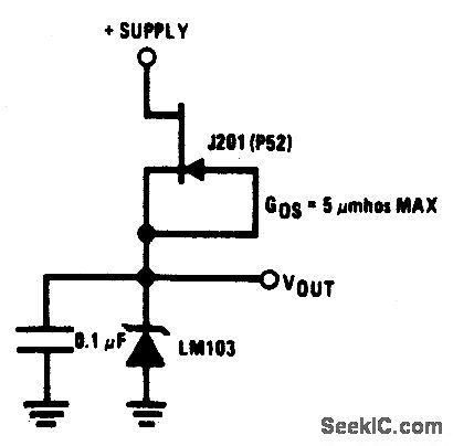
This simple reference circuit provides a stable voltage reference almost totally free of supply voltage hash. Typical power supply rejection exceeds 100 dB. (View)
View full Circuit Diagram | Comments | Reading(1166)
REMOTE_STATION
Published:2009/6/30 1:54:00 Author:May
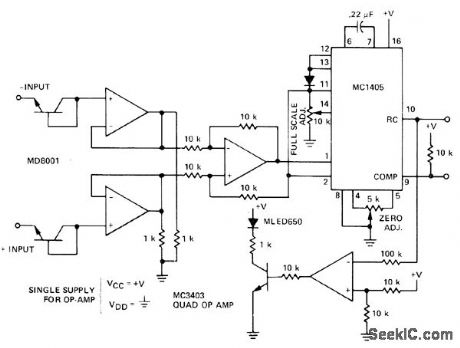
Multiplexing of large number of analog voltages from widely separated locations in large industrial control systems is simplified by transmitting two noise-immune low-frequency digital signals from each remote to central multiplexet driving display and microprocessor. Central station using MC14435 controls direction of integration in each remotestation MC1405 through ramp control output.At beginning of conversion, integrator of MC1405 integrates upward for 1000 counts of central-station clock. Integrator then ramps down while comparator remains high, with clock continuing until comparator threshold is again crossed. Counts during down ramp are latched by counter when comparator goes low, and circuits are reset for next conversion. Analog input voltage is thus transmitted to central-station MC14435 astwo digital signals.—S. Kelley, Analog Data Acquisition Network for Digital Processing Using the MC1405-MC14435 A/D System, Motorola, Phoenix, AZ, 1975, EB-58. (View)
View full Circuit Diagram | Comments | Reading(1247)
| Pages:11/34 1234567891011121314151617181920Under 20 |
Circuit Categories
power supply circuit
Amplifier Circuit
Basic Circuit
LED and Light Circuit
Sensor Circuit
Signal Processing
Electrical Equipment Circuit
Control Circuit
Remote Control Circuit
A/D-D/A Converter Circuit
Audio Circuit
Measuring and Test Circuit
Communication Circuit
Computer-Related Circuit
555 Circuit
Automotive Circuit
Repairing Circuit