
Remote Control Circuit
Index 6
DTMF encoding and decoding six-channel infrared remote controller
Published:2011/8/24 20:51:00 Author:Christina | Keyword: DTMF, encoding, decoding, six-channel, infrared, remote controller
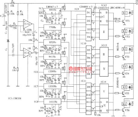
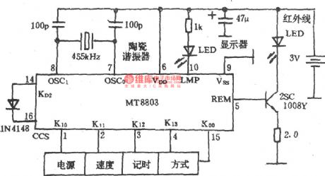
The DTMF encoding and decoding six-channel infrared remote controller is as shown in the figure.
(View)
View full Circuit Diagram | Comments | Reading(3308)
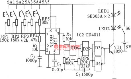
Five-channel audio equipment infrared remote controller (CX20106,NE555, CD4011, CD4017B)
Published:2011/8/23 22:37:00 Author: | Keyword: Five-channel, audio equipment, infrared, remote controller
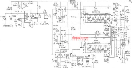
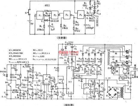
The D7630 is designed as the application-specific integrated circuit with the DC volume, tone control and balance control functions. It has strong control function, and it can be used as the multi-function control circuit of the double-channel audio power amplifier circuit. In ordinary usage, it uses the manual control mode, and it adjusts the direct voltage through the potentiometer to achieve the purpose of control. This circuit uses the D/A converter circuit to changes the digital circuit output pulse into the direct voltage.
The five-channel infrared remote control signal emitter:
Five channel audio equipment infrared remote controller:
(View)
View full Circuit Diagram | Comments | Reading(3673)
Domestic Time Controller Circuit
Published:2011/8/10 1:41:00 Author:Felicity | Keyword: Domestic, Time Controller
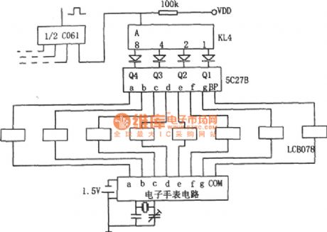
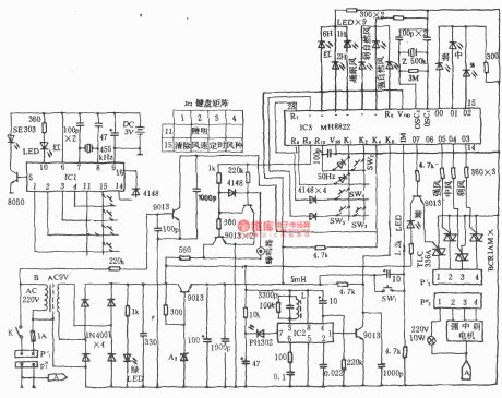
The field signal of the electric watch is voltage rising transformed by interface circuit LCB078 and then put into 5C27B field / BCD decoder. The signal is encoded as binary-decimal BCD code which is compared with the preset time signal consists of swich KL4.When the two are the same , high voltage output by main circuit will make the flip-flop to turn,and the relay drives the related load to work. When they are different , the main circuit output low voltage and the related load will not work.If it need to time several times, Multiple dial switches can be used in parallel connection. (View)
View full Circuit Diagram | Comments | Reading(1385)
Household electric fan infrared remote controller (NE555, CD4017, CD4066)
Published:2011/8/25 20:40:00 Author:TaoXi | Keyword: Household, electric fan, infrared, remote controller
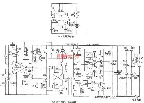
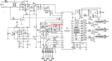
The household electric fan infrared remote controller is as shown in the figure. This remote controller has the emitter and the receiving, control parts. The infrared transmitter is designed as the astable multivibrator which is composed of the 555 and R1, W1, C1, the oscillation frequency f=1.44/(R1+2Rw1)C1, the oscillation frequency is 38kHz to drive the infrared emission diode HG310 or HG450 to output the infrared pulse. The infrared receiving tube need to use the corresponding tube, and you need to notice the optical wavelength and optical power. The IC1 uses the special infrared receiver manifold μPC1373HA.
(View)
View full Circuit Diagram | Comments | Reading(2712)
Infrared remote control fan speed control switch (555, LM324, CD4017)
Published:2011/8/25 20:49:00 Author:TaoXi | Keyword: Infrared, remote control, fan speed, control switch
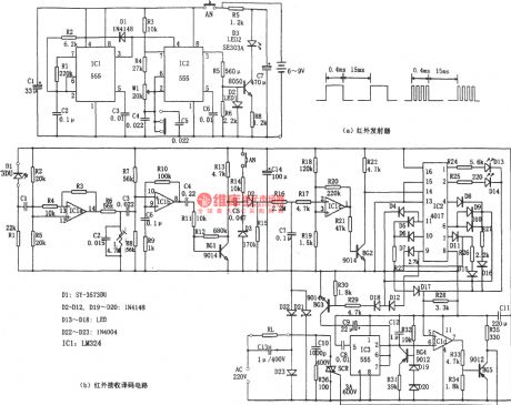
The infrared remote control fan speed control switch is as shown in the figure. This circuit is composed of the infrared transmitter, the infrared receiver, the decoder. The infrared transmitter includes the low-frequency multivibrator which is composed of the IC1 and D1, R1, R2, C2 and the multivibrator which is composed of the IC2 and R3, R4, C4, C5, W1. The oscillation cycle of IC1 is T=tcharging + tdischarging, the tcharging=0.693R2C2, it is about 400μs; tdischarging=0.693R1C2, it is about 15ms, the output waveform duty cycle is about 3%. IC2 is corresponding to two kinds of oscillation frequencies: f1=1.44/(R3+2R4+2Rw1)(C4),f2=1.44/(R3+2R4+2Rw1)(C4+C5), in the figure, the f=20kHz, f2=10kHz.
(View)
View full Circuit Diagram | Comments | Reading(3855)
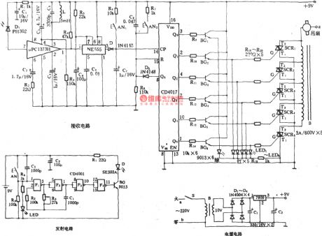
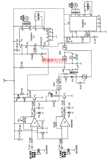
Electric fan multi-function remote control circuit
Published:2011/8/25 21:10:00 Author:TaoXi | Keyword: Electric fan, multi-function, remote control

Transmitter:
Receiver:
(View)
View full Circuit Diagram | Comments | Reading(1587)
Ceiling fan infrared remote control circuit (2)
Published:2011/8/25 21:13:00 Author:TaoXi | Keyword: Ceiling fan, infrared, remote control
Ceiling fan infrared remote control circuit (2)
(View)
View full Circuit Diagram | Comments | Reading(4642)
Ceiling fan infrared remote control circuit (1)
Published:2011/8/25 21:12:00 Author:TaoXi | Keyword: Ceiling fan, infrared, remote control

The Ceiling fan infrared remote control circuit (1)
(View)
View full Circuit Diagram | Comments | Reading(5516)
Electric fan infrared remote control circuit (Greatwall FS-19-40)
Published:2011/8/25 21:24:00 Author:TaoXi | Keyword: Electric fan, infrared, remote control, Greatwall
The Electric fan infrared remote control circuit (Greatwall FS-19-40) is as shown in the figure.
(View)
View full Circuit Diagram | Comments | Reading(1644)
Electric fan infrared remote control circuit (KD880/881)
Published:2011/8/25 21:52:00 Author:TaoXi | Keyword: Electric fan, infrared, remote control circuit
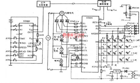
The Electric fan infrared remote control circuit (KD880/881) is as shown in the figure.
(View)
View full Circuit Diagram | Comments | Reading(2427)
Electric fan infrared remote control circuit (Greatwall FS22-40)
Published:2011/8/25 22:07:00 Author:TaoXi | Keyword: Electric fan, infrared, remote control, Greatwall
Electric fan infrared remote control circuit (Greatwall FS22-40)
The emitter:
The receiver:
(View)
View full Circuit Diagram | Comments | Reading(1539)
Electric fan infrared remote control circuit (Greatwall FS26-40)
Published:2011/8/25 22:12:00 Author:TaoXi | Keyword: Electric fan, infrared, remote control, Greatwall
Electric fan infrared remote control circuit (Greatwall FS26-40)
(View)
View full Circuit Diagram | Comments | Reading(2708)
The development of the linear matrix CCD test system based on the single chip machine
Published:2011/8/23 22:39:00 Author:qqtang | Keyword: linear matrix, CCD test system, single chip machine
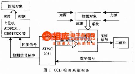
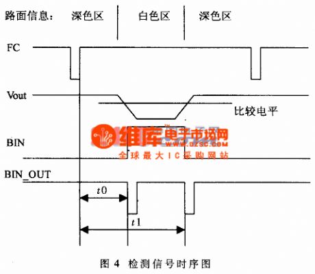
Let's assume to set a white line(the width is 300mm) on a plate of deep color (e.g black, blue and green, etc) as the moving track outgoing line of the robot, the test system of the white track is developed by using the linear matrix CCD. We first image the road information on the CCD sensitivesurface by using the optical system camera; and then the white line position is read out as the vision sense of the robot which is controlled to move along the white line. This is a typical CCD time test system.
(View)
View full Circuit Diagram | Comments | Reading(1287)
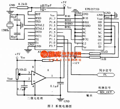
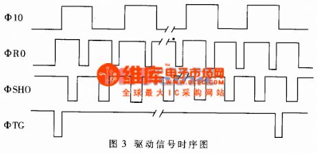
A newly linear matrix CCD circuit based on the single chip machine
Published:2011/8/23 22:39:00 Author:qqtang | Keyword: linear matrix, single chip machine
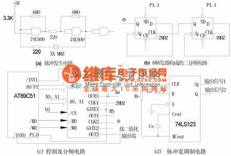
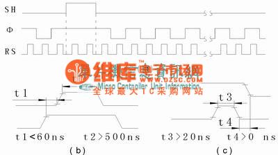
System formation This system is used to test the polarizing angle of the oars while the propeller is rotating. As the propeller has its rigidity, so it is not only swinging while rotating, but also shaking. To test its polarizing angle, the transient position of the propeller is be got, by using the imaging feature of CCD, the position information of the propeller is pictured by CCD, the light signal is switched into the electric signal, after passing the signal processing circuit, the signal is turned into digital signal which is conveyed to the CPU.
(View)
View full Circuit Diagram | Comments | Reading(1211)
Additional simple TV remote control circuit (LM555, CD4017)
Published:2011/8/26 1:45:00 Author:TaoXi | Keyword: Additional, simple, TV, remote control
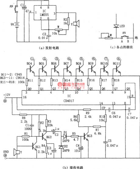
The additional simple TV remote control circuit is as shown in the figure. This circuit is composed of the launch circuit and the receiving circuit. The core of the launch circuit is the astable multivibrator which is composed of the time-base circuit 555 and the R2, W, C2, the oscillation frequency is decided by the R2, W, C2. The receiving circuit is composed of the amplification, rectification, counter circuit. The IC(CD4017) is the decimal counter/pulse distributor. The pin-9 outputs the Q8 and adds it to the pin-15 of the reset port. The CD4017 will output the Q0~Q7 which have the high level.
(View)
View full Circuit Diagram | Comments | Reading(3588)
TV power saving remote control shutdown circuit (CIC2851)
Published:2011/8/26 1:52:00 Author:TaoXi | Keyword: TV, power saving, remote control, shutdown circuit
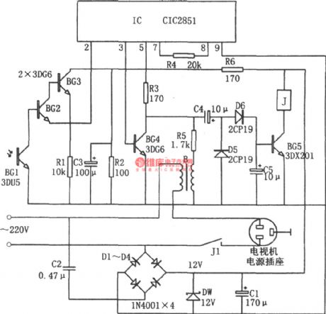
The TV power saving remote control shutdown circuit is as shown in the figure. This circuit is composed of the power supply circuit, the infrared receiver circuit, the music integrated circuit and the IC(CIC2851). When the handheld remote controller sends the signal to the TV, the phototransistor BG1 receives this signal. This signal is the pulse modulated signal, the average power is small. This signal is amplified by the BG2 to trigger the IC and makes the IC sends out the audio signal, this audio signal is rectified by D5 and D6 to produce the bias current, the bias current makes the BG5 conduct, and the relay J will close to connect the power supply of the TV.
(View)
View full Circuit Diagram | Comments | Reading(1710)
Remote control robot circuit
Published:2011/8/26 2:50:00 Author:TaoXi | Keyword: Remote control, robot
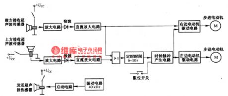
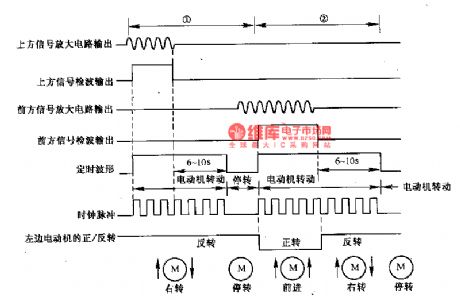
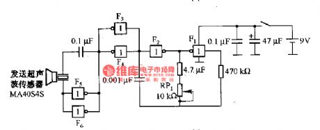
The remote control robot circuit is as shown in the figure. The figure 2-36(a) is the circuit diagram, the figure 2-36(b) is the operating timing diagram. The rotation process of the rebot is: in the circuit, the ultrasonic launching circuit is composed of the 40kHz oscillating circuit and driving circuit. The two sensors receive the ultrasonic wave: one receiving sensor is installed in the upper part of the robot; another receiving sensor is installed in front of the rebot.
In region 1, the ultrasonic sensor receives the ultrasonic wave signal and the signal is amplified by the amplifier circuit, then it is detected by the diode, at last it changes into the logic level to drive the timing circuit.
(View)
View full Circuit Diagram | Comments | Reading(2793)
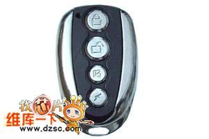
The 6-key remote control TX6006
Published:2011/8/4 1:00:00 Author:Seven | Keyword: 6-key, remote control
Code type: encode/decode PT2260/PT2262 (weld plate); study code eV1527/PT2240B; roll code HCS101/HCS301; The features of the product:Low price,good emitter handle feel, fine outline, energy-saveing, reliable working, black surface. The symbol of the rubber cushion can be set according to the need.Application range:Motor alarm product, car alarm product, domestic alarm product, short-distance wireless control product, remote control garage door, remote control electric curtain door/window, collapsible door, remote control sliding gate and industrial control, etc. (View)
View full Circuit Diagram | Comments | Reading(980)
The remote control TX5004
Published:2011/8/4 0:56:00 Author:Seven | Keyword: remote control
Code type: encode/decode PT2260/PT2262 (weld plate); study code eV1527/PT2240B; roll code HCS101/HCS301; The features of the product:Low price, small-sized emitter handle, fine outline, energy-saveing, reliable working, black surface. The symbol of the rubber cushion can be set according to the need.Application range:Motor alarm product, car alarm product, domestic alarm product, short-distance wireless control product, remote control garage door, remote control electric curtain door/window, collapsible door, remote control sliding gate and industrial control, etc. (View)
View full Circuit Diagram | Comments | Reading(1721)
The remote control TX2004
Published:2011/8/4 0:52:00 Author:Seven | Keyword: remote control
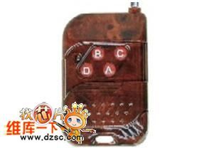
Code type: encode/decode PT2260/PT2262 (weld plate); study code eV1527/PT2240B; roll code HCS101/HCS301; The features of the product:Low price, small-sized emitter handle, fine outline, energy-saveing, reliable working, black surface. The symbol of the rubber cushion can be set according to the need.Application range:Motor alarm product, car alarm product, domestic alarm product, short-distance wireless control product, remote control garage door, remote control electric curtain door/window, collapsible door, remote control sliding gate and industrial control, etc. (View)
View full Circuit Diagram | Comments | Reading(1547)
| Pages:6/34 1234567891011121314151617181920Under 20 |
Circuit Categories
power supply circuit
Amplifier Circuit
Basic Circuit
LED and Light Circuit
Sensor Circuit
Signal Processing
Electrical Equipment Circuit
Control Circuit
Remote Control Circuit
A/D-D/A Converter Circuit
Audio Circuit
Measuring and Test Circuit
Communication Circuit
Computer-Related Circuit
555 Circuit
Automotive Circuit
Repairing Circuit