
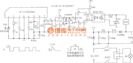
Remote Control Circuit
Index 4
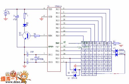
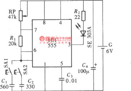
Remote electric fan circuit diagram
Published:2011/9/26 22:38:00 Author:Rebekka | Keyword: Remote electric fan
The circuit includes infrared receiver demodulation circuit, three-block speed control circuit and simulated natural wind circuit. (View)
View full Circuit Diagram | Comments | Reading(2710)
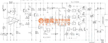
Novel infrared remote control switch circuit diagram
Published:2011/9/26 22:33:00 Author:Rebekka | Keyword: Novel infrared remote control switch
Infrared remote controlling devide is convenient and practical as the advantages of small size, low power consumption, powerful, low cost, and it is especially used in the technology commonly household appliances. In the high pressure, irradiation, toxic gases, dust and other industrial environments with infrared remote control, it is not only safe but also effectively to isolate electromagnetic interference. The circuit shows the new infrared remote control switch circuit. TVs, VCRs, air conditioners and other infrared remote control transmitter signals are pulse code modulation signal, the difference is that instruction encoding format, the signal carrier frequency is different from where we do not concern about the specific encoding instructions. (View)
View full Circuit Diagram | Comments | Reading(1504)
Five way four-function infrared remote control circuit diagram
Published:2011/9/26 22:27:00 Author:Rebekka | Keyword: infrared remote control
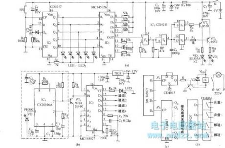
The circuit is translated and edited by MC145026. (a) figure is the remote control transmitter (b) plan is the infrared receiver and decoding circuit (c) Figure shows the controllingcontent which can be connected to each data outputend. (d) graph shows the circuit which the four data ports of MC145027topass four analog switch circuit CD4066and control the volume of an audio amplifier and speakers.
(View)
View full Circuit Diagram | Comments | Reading(2928)
Eight-way remote control circuit diagram composed of ZHF-9905 and ZHJ-9906
Published:2011/9/26 21:45:00 Author:Rebekka | Keyword: eight-way remote control circuit
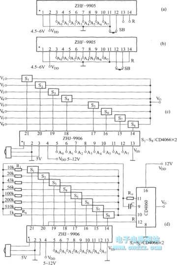
View full Circuit Diagram | Comments | Reading(991)
PC infrared remote control receiver circuit diagram
Published:2011/10/18 3:29:00 Author:Rebekka | Keyword: PC , infrared remote, control receiver
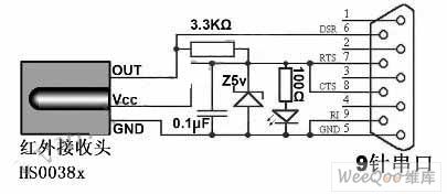
The circuit only has six components. It can remove the light-emitting diode (power indicator) and the 100Ω resistor in order to further simplify the circuit protection. Main components are HS0038A infrared remote control receiver, 5V regulator (1/4W), light emitting diodes, 9-pin serial connector, resistors (3.3KΩ and 100Ω each), electrolytic capacitors (0.1μF, 10V), universal printed circuit plate, wires (at least 3 core) and the battery box (as housing). The total costs no more than 10 yuan. (View)
View full Circuit Diagram | Comments | Reading(2693)
The eight-way remote control circuit diagram composed of module
Published:2011/9/26 21:47:00 Author:Rebekka | Keyword: eight-way remote control , module
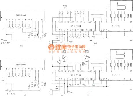
(A) is an eight-way signal remote control selection circuit composed of ZHJ-9904 ; (B) is remote control transmitter circuit; (C) is the eight-way switch control circuit; (D) is remote control transmitter. (View)
View full Circuit Diagram | Comments | Reading(1874)
Sub-ultrasonic remote control switch circuit 1
Published:2011/9/26 1:55:00 Author:Rebekka | Keyword: Sub-ultrasonic remote control switch
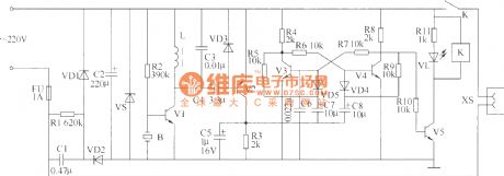
This example describes the sub-ultrasonic remote control switch. It uses pressurized gas-type sub-ultrasonic flute (It is made of rubber with olive and flat round) control. Pinch the ultrasonic whistle and the switch will be closed. The sub-ultrasonic remote control switches can be used to control lighting, exhaust fan and some minor electrical equipment. The ultrasonic remote control switch circuit is composed of the sub-circuit, the power supply, sub-ultrasonic control circuit, bistable trigger and control implementation circuit. Here is the circuit.
Components selection R1 uses 1/2W metal film resistors; R2 ~ R11 use 1/4W carbon film resistors use or metal film resistors. C1 uses 400Vpolyester capacitor or CBB capacitor; C2, C4, C5, C7 and C8 use aluminium electrolytic capacitors with thevoltage in 16V; C3 and C6 use monolithic capacitors. VD1 and VD2 use 1N4007 silicon rectifier diodes; VD3 ~ VD5 uses 1N4148 silicon switching diode. VS uses 1W, 9V voltage silicon diode. VL uses φ3mm green light-emitting diodes. (View)
View full Circuit Diagram | Comments | Reading(1464)
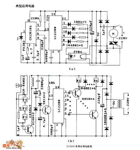
LJC2200 (air conditioner, electric fan, tape recorder) radio remote control receiver circuit
Published:2011/10/14 2:19:00 Author:Ecco | Keyword: air conditioner, electric fan, tape recorder, radio remote control , receiver
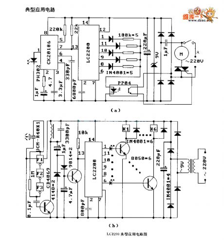
View full Circuit Diagram | Comments | Reading(2117)
The remote control circuit diagram made of singlechip
Published:2011/9/14 22:43:00 Author:Rebekka | Keyword: remote control , singlechip
View full Circuit Diagram | Comments | Reading(1351)
The time delay circuit diagram composed of transistor
Published:2011/9/13 1:51:00 Author:Rebekka | Keyword: transistor , time delay
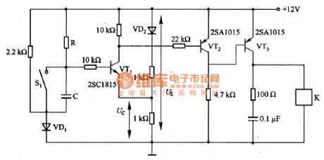

(a) Timedelay circuit
(b) Timedelay circuit
It can set delay time according to the voltage Us and resistor R. In the circuit, S1 is the the discharge switch of capacitor C. When the switch S1 is closed, the stored charge on C will be released through S1 to ensure the accuracy of the delay time the next time. VD1 and VD2 are used to eliminate the impact of VT1 by its voltage UBE. In the circuit, the load current can be only 5OnA. If VT3 is replaced by Darlington transistor, the load current will be increased. VT1 uses 2SC1815; VT2 and VT3 use 2SAlO15; VD1 and VD2 use 1S1588. Delay time T = RC1n1 / (1-K), K = Uc / Us. Figure 1 (b) is a time delay circuit composedof the transistor and the comparator. It is similar with the circuit shown in Figure 1(a). The comparison circuit uses comparator integrated chip M51206L. It is not effected by environmental temperature and supply voltage variations. Therefore, the circuit is very stable. If VT2 uses the Darlington power transistor, you can drive higher current load.
(View)
View full Circuit Diagram | Comments | Reading(3313)
Ten-channel ALC
Published:2011/9/12 21:07:00 Author:Ecco | Keyword: Ten-channel ALC

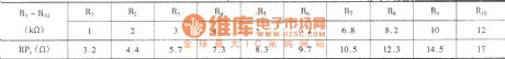
The circuit can control ten roads of load (such as lights), and each load receiver controllers are independent, non-interfering, easy to use. The figure (A) shows the remote control transmitter, and figure (b) shows the remote control receiver circuit. Adjustable resistor RPx, parameters are as follow:
(View)
View full Circuit Diagram | Comments | Reading(1567)
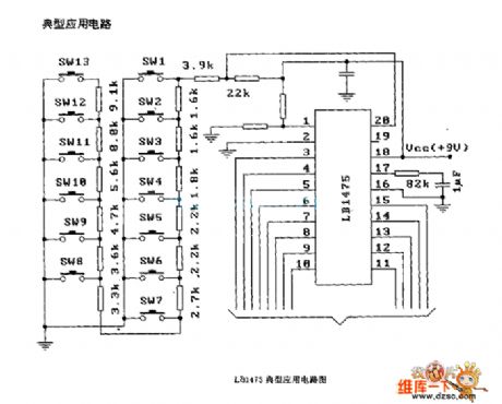
LBl475 two-wire remote control circuit diagram
Published:2011/9/19 1:40:00 Author:Ecco | Keyword: two-wire remote control
View full Circuit Diagram | Comments | Reading(2391)
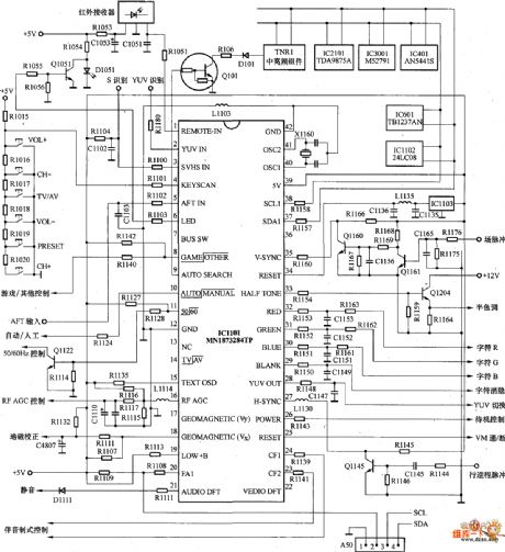
Panasonic ( National ) mx8c movement color TV remote control circuit diagram
Published:2011/9/1 1:08:00 Author:Ecco | Keyword: Panasonic, National movement, color TV , remote control
View full Circuit Diagram | Comments | Reading(6256)
LJC2200 infrared, ultrasonic and radio remote control receiver circuit diagram
Published:2011/9/8 1:11:00 Author:Ecco | Keyword: infrared, ultrasonic , radio , remote control receiver
View full Circuit Diagram | Comments | Reading(3470)
Simple current limiting circuit
Published:2011/9/12 21:59:00 Author:John | Keyword: current limiting
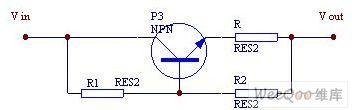
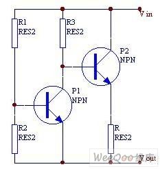
When the current is less than the value set, the bias current provided by R1 leads the P3 to be saturated to conduct. And it can not afford to control the current. When the current is greater than or equal to the set value, the pressure drop on R would increase and be close to the pressure drop of R2 after acrossing the transistor junction. Then it can limit the current through P3 in order to limit the current to a certain level. If R2 is used as a regulator instead, the limiting performance can be more accurate. The drawback of the introduced protection circuit is that the pressure drop can be all down on the transistor when the current is overload, especially a short circuit. Thus, it would lead to certain power consumption.
(View)
View full Circuit Diagram | Comments | Reading(7505)
Infrared remote control volume potentiometer (CD4528, CD40193, CD4067)
Published:2011/9/12 21:53:00 Author:Christina | Keyword: Infrared, remote control, volume potentiometer
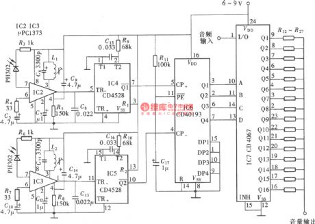
The volume potentiometer is composed of the CMOS digital integrated circuit, and it can be used as the volume control potentiometer of the home audio power amplifier circuit. And it can be used as the voltage regulator of other electrical equipments or instruments. The circuit is as shown in the figure. The full-circuit is composed of the double-channel infrared remote control transmitter, the double-channel infrared receiving signal amplifier, the channel selection and controller, the resistance network and the adding and subtracting controller.
The launch circuit:
The receiving circuit:
(View)
View full Circuit Diagram | Comments | Reading(8648)
Level Instruction Drive Circuit
Published:2011/9/4 7:26:00 Author:Joyce | Keyword: Level , Instruction , Drive
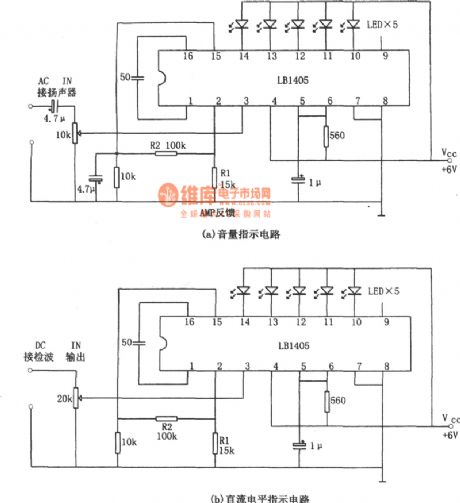
As shown in the figure is the LB1405 / LB1415 level instruction drive circuit. Figure (a) is an application circuit of LB1405 / LB1415 used as volume instruction, and figure (b) is an application circuit of LB1405 / LB1415 used as dc level instruction. The corresponding closed-loop gain of figure (a) is R2 / R1.Adjusting the 10 kΩ potentiometer will get the point of 0 dB. In the circuit, five stick leds are used to indicate the level of input signal. (View)
View full Circuit Diagram | Comments | Reading(3493)
0~16 Hours Stepless Timing Controller Circuit (NE555, CD4040)
Published:2011/9/6 4:45:00 Author:Felicity | Keyword: Stepless, Timing Controller
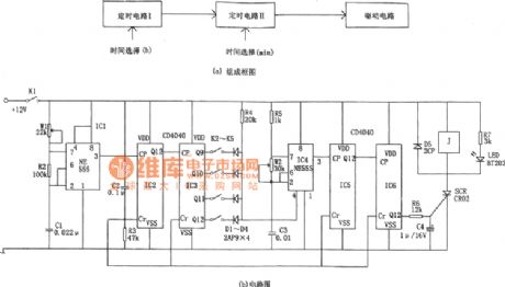
This controller consists of two stage timer and driver. Timing circuit 1 consists of IC1(555) and two 12 bit binary counter/frequency divider IC2 and IC3(CD4040) to produce totally 16 adjustable timing signal as:0,1,2......14,15hour(s). Timing circuit Ⅱwhich is controlled by timing circuit I consists of IC4(555) and two 12 bit binary counter/frequency divider IC5 and IC6(CD4040) .Timing circuit controls timing circuit Ⅱby the reset terminal of IC4 and timer I can produce 0~60 minutes continuously adjustable timing signal. (View)
View full Circuit Diagram | Comments | Reading(2352)
The infrared remote control dimmer switch circuit KA2184A
Published:2011/9/4 20:34:00 Author:TaoXi | Keyword: Infrared, remote control, dimmer switch
The circuit is as shown in the figure. It includes the infrared emission circuit, the infrared receiver circuit, the decoder circuit, the dimming control circuit and the birds voice circuit.etc. You can use this circuit to achieve the remote control switching and dimming of the wall lamp, droplight, the remote control distance is more than 7m, and it is easy to operate and has reliable performance.
Infrared emission circuit:
Oscillation frequency:
Infrared receiving control circuit:
(View)
View full Circuit Diagram | Comments | Reading(1173)
The infrared remote control music socket circuit 3
Published:2011/9/4 20:35:00 Author:TaoXi | Keyword: Infrared remote control, music socket
The circuit is as shown in the figure. It includes the infrared remote transmitter circuit, the decoder circuit, the relay control circuit and the music circuit.etc. The infrared pulse transmitter circuit is composed of the 25kHz pulse oscillation circuit and the external transmitter driver circuit. And the 25kHz pulse oscillator is composed of the F1, F 2 and R1, R2, C1 components which belong to the Six NAND gate IC CD4069.
Infrared transmitter circuit:
Infrared receiver and control circuit:
(View)
View full Circuit Diagram | Comments | Reading(1034)
| Pages:4/34 1234567891011121314151617181920Under 20 |
Circuit Categories
power supply circuit
Amplifier Circuit
Basic Circuit
LED and Light Circuit
Sensor Circuit
Signal Processing
Electrical Equipment Circuit
Control Circuit
Remote Control Circuit
A/D-D/A Converter Circuit
Audio Circuit
Measuring and Test Circuit
Communication Circuit
Computer-Related Circuit
555 Circuit
Automotive Circuit
Repairing Circuit