
Remote Control Circuit
Index 16
MC9482 (electronic toy) remote control receiving decoder circuit
Published:2011/7/17 5:46:00 Author:Christina | Keyword: electronic toy, remote control, receiving, decoder
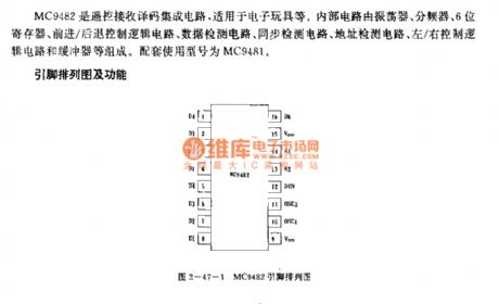
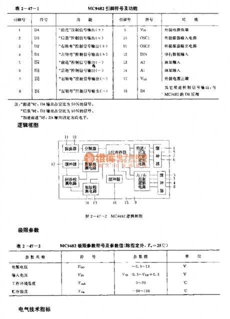
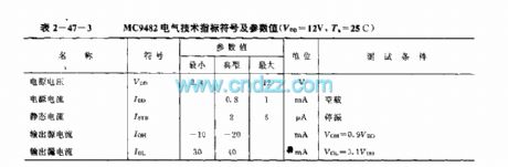
The MC9482 is designed as one kind of remote control receiving decoder circuit that can be used in the electronic toys. The internal circuit is composed of the oscillator, the frequency divider, the 6-bit register, the forward/back control logic circuit, the data detection circuit, the synchronous detection circuit, the address detection circuit, the left/right control logic circuit and the buffer. The matching model is MC9481.
(View)
View full Circuit Diagram | Comments | Reading(1193)
MN6011 (VCR) infrared remote control launch circuit
Published:2011/7/17 8:04:00 Author:Christina | Keyword: VCR, infrared, remote control, launch circuit
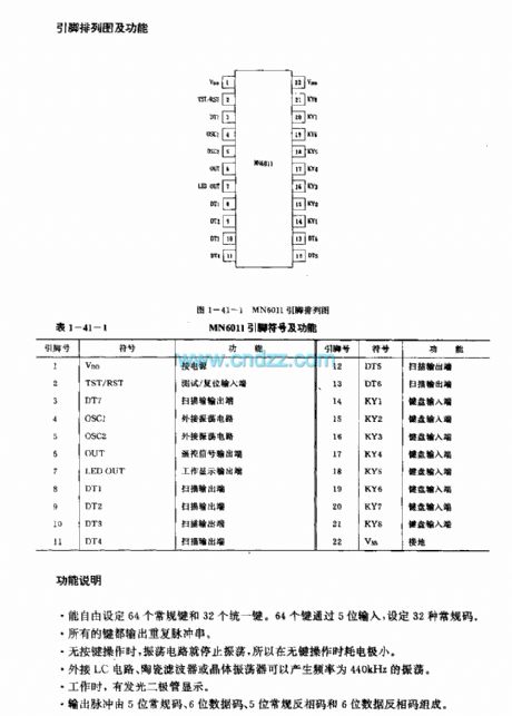

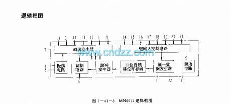
The MN6011 is designed as one kind of multi-function infrared remote control transmitter integrated circuit, and it can be used in the VCR. The internal circuit is composed of the oscilation circuit, the key input control circuit, the tuning generator, the pulse generator, the modulation circuit, the 11-bit self-locking shift register and the unified data generator.
Features
The CMOS technology very large scale integrated circuit (VLSI)The typical value of the power supply voltage is 3V.
Function description
It can set 64 conventional keys and 32 unified keys freely.All the keys can output the repetitive pulse sequence.When there is no key operation, the oscillation circuit will stop working.The external, LC circuit, ceramic filters and crystal oscillator can produce the 440kHz oscillating wave.The LED display.The output pulse is composed of the 5-bit conventional code, the 6-bit data code, the 5-bit conventional RP code and the 6-bit data RP code.
(View)
View full Circuit Diagram | Comments | Reading(1460)
MN6021 (TV) infrared remote control transmitter circuit
Published:2011/7/17 8:16:00 Author:Christina | Keyword: TV, infrared, remote control, transmitter
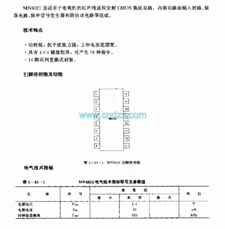
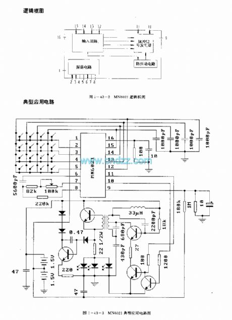
The MN6021 is designed as one kind of infrared remote control transmitter CMOS integrated circuit that can be used in the TV sets. The internal circuit is composed of the input loop, the oscillating circuit, pulse signal generator and the anti-jitter circuit.
Features
The low power consumption, strong anti-interference ability and wide operating voltage range .It has the 4X4 keyboard matrix to produce the 16 kinds of commands.16-pin dual-row DIP package.
(View)
View full Circuit Diagram | Comments | Reading(1923)
MN6014/S infrared remote control transmitter circuit
Published:2011/7/17 8:23:00 Author:Christina | Keyword: infrared, remote control, transmitter circuit
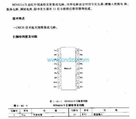
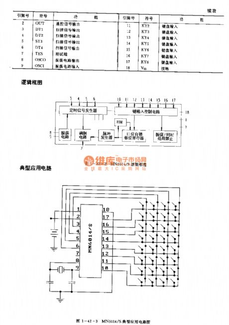

The MN6014/S is designed as one kind of infrared remote control transmitter circuit. The internal circuit is composed of the timing signal generator, the oscilation circuit, the key input control circuit, the tuning generator, the pulse generator, the modulation circuit, the 11-bit self-locking shift register.
Features
The CMOS technology very large scale integrated circuit (VLSI)
Function description
When there is no key operation, the oscillation circuit will stop working.
When you press the button several times, the output will be forbided.
It supplies 32 buttons.
(View)
View full Circuit Diagram | Comments | Reading(1268)
MN6930B(VCR)infrared remote control transmitter circuit
Published:2011/7/17 8:56:00 Author:Christina | Keyword: VCR, infrared, remote control, transmitter circuit
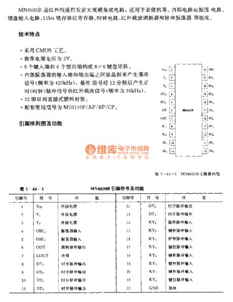
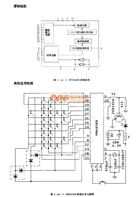
The MN6930B is designed as one kind of infrared remote control transmitter large scale integrated circuit, and it can be used in the VCR. The internal circuit is composed of the oscillating circuit, the keyboard input circuit, the 11-bit self-locking shift register, the clock circuit, the infrared wave-carrier modulator and the pulse oscillator.
Features
The CMOS technology.The recommend power supply voltage is 3V.The 8X6 keyboard matrix is composed of 8 type-in ports and 6 type-out ports.The crystal oscillator is connected between the input port and the output port of the internal oscillator to produce the benchmark signal (the frequency is 420kHz).The 22-pin dual-row DIP package.The matching models are M50110P/AP/BP/CP.
(View)
View full Circuit Diagram | Comments | Reading(1642)
MK5087 general infrared remote control transmitter circuit (dual-tone multiple-frequency signal generating circuit)
Published:2011/7/17 9:12:00 Author:Christina | Keyword: general, infrared, remote control, transmitter, dual-tone, multiple-frequency, signal, generating circuit

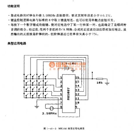
The MK5087 is designed as one kind of dual-tone multiple-frequency signal generating circuit that can be used in the radio transmission circuits. The internal circuit is composed of the clock oscillating circuit, the keyboard control logic circuit, the programmable frequency divider, the bass group D/A circuit, the treble group D/A circuit, the counting circuit and the squelch circuit.
Features
The voltage range of the power supply is 2.5-15V,The 16-pin dual-row DIP plastic package.
Function description
It can set 64 conventional keys and 32 unified keys freely.All the keys can output the repetitive pulse sequence.When there is no key operation, the oscillation circuit will stop working.The external, LC circuit, ceramic filters and crystal oscillator can produce the 440kHz oscillating wave.The LED display.The output pulse is composed of the 5-bit conventional code, the 6-bit data code, the 5-bit conventional RP code and the 6-bit data RP code.
(View)
View full Circuit Diagram | Comments | Reading(2095)
The temperature connector circuit of LX5600
Published:2011/7/14 6:19:00 Author:Borg | Keyword: temperature connector
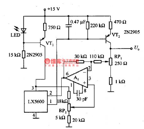
This is the temperature connector circuit of LX5600. In the circuit, LED and VT1 compose the constant current circuit, which provides with working current of LX5600. VT2 is the low output impedance amplifier, which magnifies the output signal of LX5600; A1 is the phase reverser, which completes the backward feedback; RP1 is used to regulate the converting sensibility; RP2 is used to zero set. The output voltage is 0-5v, the temperature of 100℃ is corresponding to the voltage of 4V.
(View)
View full Circuit Diagram | Comments | Reading(1205)
The thermometer circuit composed of LX5600
Published:2011/7/14 6:09:00 Author:Borg | Keyword: thermometer circuit
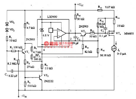
When this thermometer is used in the room, it can work in the intermittent way, and this working state can be kept in the temperature test circuit, because internal temperature doesn't change sharply. The astable multi-resonance oscillator consists of VT1 and VT2, i.e the interval oscillator circuit, which samples per 1s, and the interval time ratio is 0.2%, the power supply is 8-12V. C1 and R3 decide the block time of the oscillating circuit, C1, R1, R4 and R7 decide the conducting time of the interval oscillating time. (View)
View full Circuit Diagram | Comments | Reading(1743)
bean sprout automatic watering thermostat
Published:2011/7/13 22:13:00 Author:chopper | Keyword: bean sprout, automatic watering, thermostat
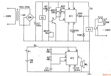
It should control the growth temperature and water at regular time when we produce bean sprout,and the manual operation is relative complicated. This example describes the bean sprouts automatic watering thermostat, with outage alarm function.It can automatically control the growth temperature of bean sprouts, and can water bean sprout by the temperature automatically,thus the bean sprouts can grow in an optimal growth temperature range. The principle of circuitThis bean sprout automatic watering thermostat is formed by the power supply circuit,the temperature detection control circuit and outage alarm circuit, which is shown in figure 4-207.
(View)
View full Circuit Diagram | Comments | Reading(1607)
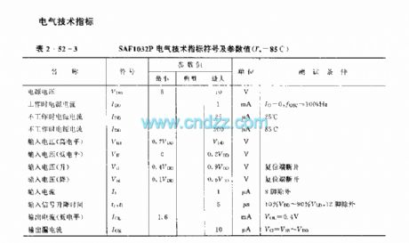
SAFl039P (TV set, audio equipment and industrial control equipment) infrared remote control receiving decoder circuit
Published:2011/7/12 7:36:00 Author:Christina | Keyword: TV set, audio equipment, industrial control equipment, infrared remote control, receiving, decoder
The SAF1032P is designed as one kind of infrared remote control receiving decoder circuit that can be used in the TV set, audio equipment and industrial control equipment applications.
Features
It uses the LOCMOS technology, so the power consumption is small;The static keyboard matrix;32-jump control instruction;It has two kinds of launch modes that can be choosed;The input and output parts can prevent the electrostatic effect in different practical conditions, even so, you need to use it according to the operation rule;It uses the 16-pin dual-row DIP plastic package;The supporting model is SAF1032P.
(View)
View full Circuit Diagram | Comments | Reading(918)
SAFl032F (TV set, audio equipment and industrial control equipment) infrared remote control receiving decoder circuit
Published:2011/7/12 7:58:00 Author:Christina | Keyword: TV set, audio equipment, industrial control equipment, infrared remote control, receiving, decoder
The SAF1032P is designed as one kind of infrared remote control receiving decoder circuit that can be used in the TV set, audio equipment and industrial control equipment applications. The internal circuit is composed of the digital displacement registers (SRDT), the timer counter (CTIM), the comparator, the binary output flag (BWF), the binary selection flag (SELF), the buffer register (BFR), the analog decoder (ANDEC), the linear register (LIN), the comparator counter and the bit counter.
Features
It uses the LOCMOS technology, so the power consumption is small;It uses the single power supply operating mode;It has 16 program selective codes, and it has the anti-error code function;It has the auto-setup function;It has three analog control functions, every control process has 63 steps;The input and output parts can prevent the electrostatic effect in different practical conditions, even so, you need to use it according to the operation rule;It uses the 18-pin dual-row DIP plastic package;The supporting model is SAF1039P.
(View)
View full Circuit Diagram | Comments | Reading(928)
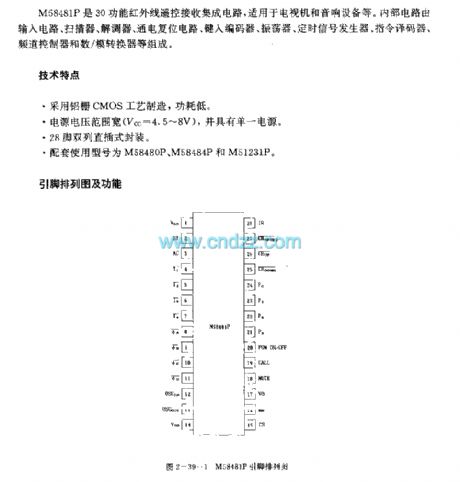
M58485P (TV and audio equipment) 29 functions infrared remote control receiving circuit
Published:2011/7/12 8:20:00 Author:Christina | Keyword: TV, audio equipment, 29 functions, infrared remote control, receiving circuit
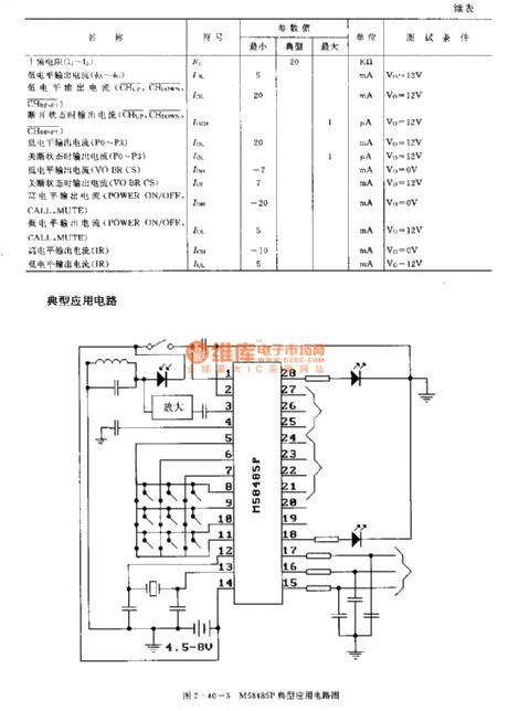
The M58485P is designed as one kind of 29 functions infrared remote control receiving circuit, and it can be used in the TV and audio equipment applications. The internal circuit is composed of the input circuit, the scanner, the modem, the power-on reset circuit, the type encoder, the oscillator, timing signal generator, instruction decoder, channel controller and the D/A converter, and it is in the 28-pin dual-row DIP package.
(View)
View full Circuit Diagram | Comments | Reading(1294)
M58487AP (TV and audio equipment) 24 functions infrared remote control receiving circuit
Published:2011/7/12 8:31:00 Author:Christina | Keyword: TV, audio equipment, 24 functions, infrared remote control, receiving circuit

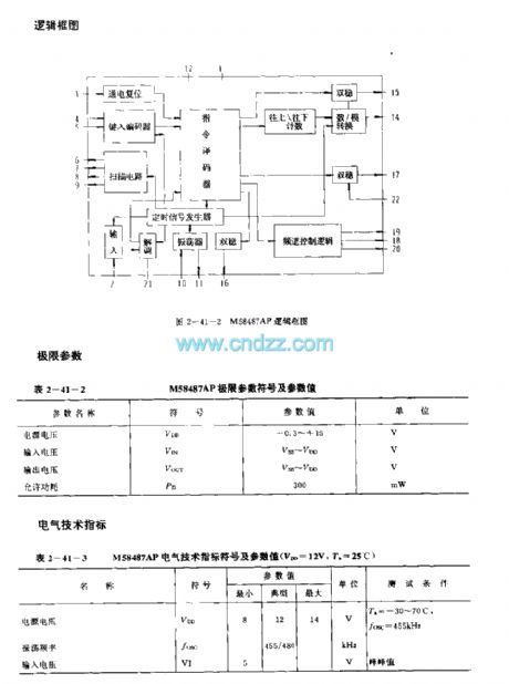
The M58487AP is designed as one kind of 24 functions infrared remote control receiving circuit, and it can be used in the TV and audio equipment applications. The internal circuit is composed of the input circuit, the scanner, the modem, the power-on reset circuit, the type encoder, the oscillator, timing signal generator, instruction decoder, channel controller and the D/A converter.
Features
It uses the aluminum-gate CMOS process, the power consumption is low;The voltage range of the power supply is wide, and it has the single power supply;The oscillation circuit can connect with the ceramic or LC as the resonant component;The good anti-noise performance;The carrier frequency has the single transmitting frequency;The receiving end can control 8 instructions, and it has 8 functions;It allows the operating frequency to have the large error between the transmitter and receiver;It can be used with the M58480P,M58484P and M51231P;It is in the 22-pin dual-row DIP package.
(View)
View full Circuit Diagram | Comments | Reading(980)
M50126P (TV set) infrared remote control receiving circuit
Published:2011/7/12 8:48:00 Author:Christina | Keyword: TV set, infrared remote control, receiving circuit
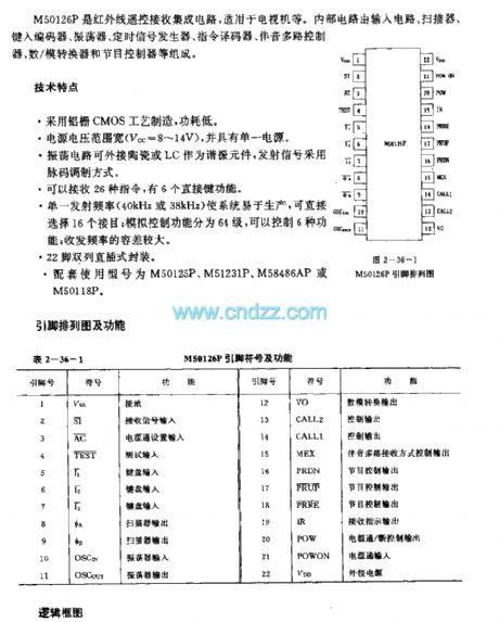
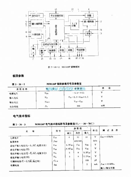
The M50126P is designed as one kind of infrared remote control receiving circuit, and it can be used in the TV set application. The internal circuit is composed of the input circuit, the scanner, the type-in encoder, the oscillator, the timing signal generator, the instruction decoder, the multi-channel audio controller, the D/A converter and the program controller.
Features
It uses the aluminum-gate CMOS process, the power consumption is low;The voltage range of the power supply is wide, and it has the single power supply;The oscillation circuit can connect with the ceramic or LC as the resonant component;The good anti-noise performance;It can receive 26 kinds of instructions, and it has 6 direct button functions;It can be used with the M50125P,M51231P and M58486P, M50118P;It is in the 22-pin dual-row DIP package.
(View)
View full Circuit Diagram | Comments | Reading(1175)
M51242P (TV and audio equipment) three functions infrared remote control receiving circuit
Published:2011/7/13 6:59:00 Author:Christina | Keyword: TV, audio equipment, three functions, infrared remote control, receiving circuit
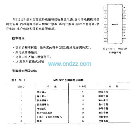
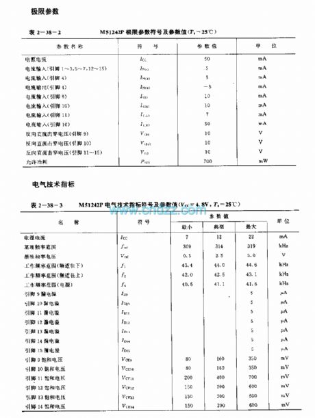
The M51242P is designed as one kind of six functions infrared remote control receiving integrated circuit that can be used in the TV set and the audio equipment applications. The internal circuit is composed of the input frequency counter, the decode counter, the pulse control circuit, the latch circuit, the coincidence circuit and the decoding circuit.
Features
It has stable frequency standard and low frequency distortion;Open collector output;The circuit has the Zener voltage stabilization diode;16-pin dual-row DIP package.
(View)
View full Circuit Diagram | Comments | Reading(971)
M58481P (TV and audio equipment) 30 functions infrared remote control receiving circuit
Published:2011/7/13 6:59:00 Author:Christina | Keyword: TV, audio equipment, 30 functions, infrared remote control, receiving circuit
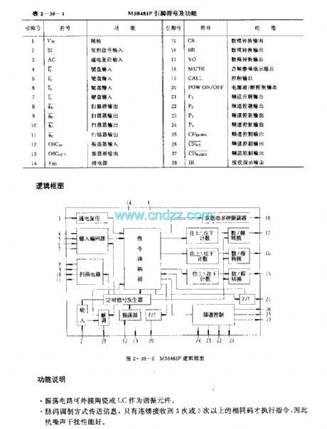
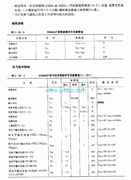
The M58481P is designed as one kind of 30 functions infrared remote control receiving circuit, and it can be used in the TV and audio equipment applications. The internal circuit is composed of the input circuit, the scanner, the modem, the power-on reset circuit, the type encoder, the oscillator, timing signal generator, instruction decoder, channel controller and the D/A converter.
Features
It uses the aluminum-gate CMOS process, the power consumption is low;The voltage range of the power supply is wide, and it has the single power supply;It can be used with the M58480P,M58484P and M51231P;It is in the 22-pin dual-row DIP package;The oscillation circuit can connect with the ceramic or LC as the resonant component.
(View)
View full Circuit Diagram | Comments | Reading(934)
M51240P (TV set and the audio equipment) 6 functions infrared remote control receiving circuit
Published:2011/7/13 7:08:00 Author:Christina | Keyword: TV set, audio equipment, 6 functions, infrared remote control, receiving circuit
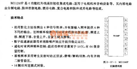
The M51240P is designed as one kind of six functions infrared remote control receiving integrated circuit that can be used in the TV set and the audio equipment applications. The internal circuit is composed of the input frequency counter, the decode counter, the pulse control circuit, the latch circuit, the coincidence circuit and the decoding circuit.
Features
You can use the digital method to test out six kinds of signal frequenciesThe digital low-pass filter can be used to eliminate the noise effect and supply the stable operation;It has two kinds of control frequencies;The circuit has the Zener voltage stabilization diode;16-pin dual-row DIP package.
(View)
View full Circuit Diagram | Comments | Reading(938)
A Simple Timer Circuit Composed of MC14541
Published:2011/7/9 2:06:00 Author:Joyce | Keyword: Simple, Timer
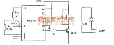
As shown in the figure is a simple timer circuit composed of MC14541, which is an integrated circuit. According to the parameters in the figure, its timing time is 3hours, and it can use different values of RTC、CTC and Rs to get various needed timing control .
(View)
View full Circuit Diagram | Comments | Reading(2967)
Long Time Timing Circuit
Published:2011/7/9 2:14:00 Author:Joyce | Keyword: Long Time , Timing
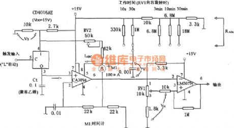
As shown in the figure is a long time timing circuit. This circuit uses the discharging mode of controllable operation amplifier CA3094 to get long time timing. In order to change the fixed time continuously, it is usually achieved by changing VH through RV1.
(View)
View full Circuit Diagram | Comments | Reading(956)
Precise Digital Timing Controller Circuit
Published:2011/7/9 2:31:00 Author:Joyce | Keyword: Precise , Digital , Timing , Controller
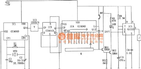
As shown in the figure is a precise digital timing controller circuit, which is composed of a crystal oscillator circuit, a frequency divider, a counting circuit and a monostable trigger.
The crystal oscillator circuit constitutes of a 14 bit binary serial count/distributor, a clock crystal (32768 Hz), C1, C2 etc.The crystal signal will be output through feet③(Q14) after being divided 214 times .Then it will be inverted by IC2 and then divided by double D flip-flop CC4013 (IC3) to be a signal of 1 Hz. The signal will be added to the CP end of IC4 as the control signal of the clock.
IC4 is a 12 bit binary serial count/distributor CC4040, when the signal frequency of CP is 1 Hz ac, the 11 output ends Q4 ~Q9, Q12 ~ Q14 are to output pulse(phase step high level) of 2 seconds, 4 seconds, 8 seconds, 16 seconds, 32 seconds, 64 seconds, 128 seconds, 256 seconds, 512 seconds, 1024 seconds, 2048 seconds respectively. (View)
View full Circuit Diagram | Comments | Reading(1223)
| Pages:16/34 1234567891011121314151617181920Under 20 |
Circuit Categories
power supply circuit
Amplifier Circuit
Basic Circuit
LED and Light Circuit
Sensor Circuit
Signal Processing
Electrical Equipment Circuit
Control Circuit
Remote Control Circuit
A/D-D/A Converter Circuit
Audio Circuit
Measuring and Test Circuit
Communication Circuit
Computer-Related Circuit
555 Circuit
Automotive Circuit
Repairing Circuit