
Remote Control Circuit
Index 2
Hn2c ( electric fan) Remote coding circuit
Published:2011/8/31 1:20:00 Author:Jessie | Keyword: Remote coding
HT12C is remote coding circuit, which isapplicable to the electric fan, etc. It uses double row 18-pin plastic packaging, and supports the use of the model HT6337A.
Functional specification:12 remote coding circuit;Three kinds of wind output;Three wind speed selection;Automatic room temperature control air volume, contact protection function, up, down, left and right shook head, all buttons with key sound;
Manual/remote control.
(View)
View full Circuit Diagram | Comments | Reading(2204)
HD43019A ( TV and video) infrared remote control launch circuit
Published:2011/8/31 1:19:00 Author:Jessie | Keyword: TV , video , infrared remote control , launch circuit
HD43019A is infrared remote control transmit circuit is applicable to the TV and video, etc. The Internal circuit is composedof theoscillator, counter, input decoder, code generator and double road input protection circuit, etc. Technical features: CMOS technology, low power consumption; 16-pin DIP, transmitting 28 kinds of instructions; 18-pin DIP, transmitting 64 kinds of instructions; Oscillating circuit is applies to external 455kHz LC or ceramic filter; 16-pin and 18-pin DIP.
(View)
View full Circuit Diagram | Comments | Reading(1631)
HD430196B (TV and video) Infrared remote control transmit circuit
Published:2011/8/26 3:41:00 Author:Jessie | Keyword: Infrared, remote control transmit
HD30196B is the infrared remote control transmit circuit, which is applicable to the TV and video, etc. The Internal circuit is composedofoscillator, counter, input decoder, code generator and double road input protection circuit, etc. Technical features: CMOS technology, low power consumption; Strong anti-interference ability; External components is less, the instructions is more; Oscillating circuit can use LC oscillators, and 455kHz ceramic filter; It can prevent multiple keys frompressingand misoperation at the same time; 18 feet DIP.
(View)
View full Circuit Diagram | Comments | Reading(1279)
1RTl260(TV and video)infrared remote control transmission circuit
Published:2011/8/30 2:24:00 Author:Jessie | Keyword: infrared, remote control
IRT1260 is theinfrared remote control transmission circuit,which issuitable for TV and video, etc. The Internal circuit is composedof the oscillator, clock generator, procedures controller, input detection circuit, decoder, address ROM, output amplifier etc.
Technical characteristicsCMOS technology, low power consumption.24-pin DIP.
(View)
View full Circuit Diagram | Comments | Reading(995)
Multi-function program-controlled flash integrated circuit composed of CD71061
Published:2011/11/4 1:49:00 Author:May | Keyword: Multi-function , program-controlled , flash integrated circuit
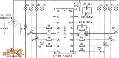
Multi-function program-controlled flash integrated circuit is shown in the diagram. It can ordinal display six basic patterns, namely elastic shrinkage, full light withinterval flash,negativeflowing to left with water, positiveflowing to the right with water, and meanwhile bright in left turn. This six basix patterns can be circularly displayed, and the cricularly times is controlled.
(View)
View full Circuit Diagram | Comments | Reading(2288)
Human infrared remote sensing lamp circuit
Published:2011/11/3 22:14:00 Author:May | Keyword: Human infrared remote sensing lamp
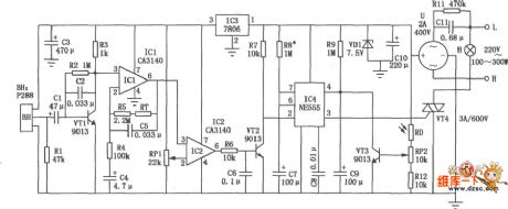
The diagram is human infrared remote sensing lamp circuit. It uses trace infrared heat sent out by human to remote control the open or close of lap. This human infrared remote sensing lamp trigger sensitivity is very high ( can work in 10m distance), anti-jamming ability is strong, and ittruly achieces full automation.
(View)
View full Circuit Diagram | Comments | Reading(3804)
Ultrasonic remote control switching circuit diagram
Published:2011/9/16 1:04:00 Author:Rebekka | Keyword: Ultrasonic remote control, switching circuit
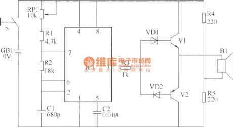
This example describes the ultrasonic remote control switch. The remote distance is 10m or more. It can be widely used in industrial automation control and home appliance control. The ultrasonic remote control switching circuit is composed of an ultrasonic transmitter circuit and receiver circuit. Ultrasonic transmitter circuit is composed of the control button S, time-base integrated circuit IC1, transistors V1, V2, resistors R1 ~ R5, potentiometer RP1, diode VD1, VD2, capacitors C1, C2 and the first ultrasonic transmitter composed of B1. Here is the circuit.
Ultrasonic transmitter circuit
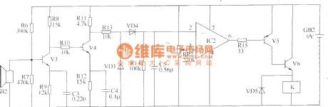
Ultrasonic receiver circuit is composed of an ultrasonic receiver B2, transistors V3 ~ V5, operational amplifier integrated circuit IC2, relay K, the diode VD3 ~ VD5 and resistors R6 ~ R15, capacitors C3 ~ C5, potentiometers RP2 and other components. Here is the circuit.
Ultrasonic receiver circuit.
Optional components selectionR1 ~ R15 use 1/4W carbon film resistors or metal film resistors. RP1 and RP2 use small potentiometers or sealed variable resistors. C1 uses high-frequency ceramic capacitors; C2 ~ C5 use monolithic capacitors or polyester capacitors.VD1 ~ VD5 use 1N4148 silicon switching diodes. V1, V3 and V4 use S9014 silicon NPN transistors; V2 and V5 use S9015 silicon PNP transistors; V6 uses S9013 or C8050 silicon NPN transistor. IC1 uses NE555 or 5G1555 time-base circuit; IC2 uses μA741 or CA3140, LF351 etc. integrated circuits. B1 uses T40 ultrasonic transmitter emission terminal; 82 uses R40 ultrasonic receiver terminal. K uses universal 9V DC relay,andthe capacity of visual contact may be controlled by electrical power.
(View)
View full Circuit Diagram | Comments | Reading(2783)
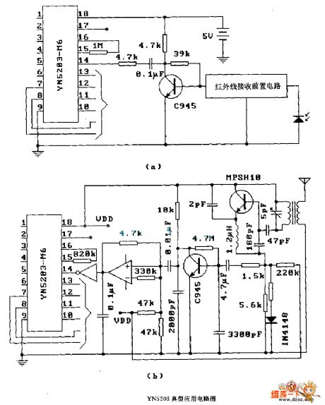
YN 5203 ( anti-theft system) radio or infrared remote control decoding circuit diagram
Published:2011/12/8 20:49:00 Author:Ecco | Keyword: anti-theft system, radio , infrared , remote control , decoding
View full Circuit Diagram | Comments | Reading(2140)
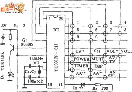
Panda 3643 remote control transmitter schematic diagram
Published:2011/12/9 0:17:00 Author:Ecco | Keyword: Panda , remote control, transmitter, schematic diagram
View full Circuit Diagram | Comments | Reading(1641)
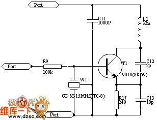
Radio remote control transmitter circuit diagram
Published:2011/10/18 3:41:00 Author:Ecco | Keyword: Radio remote control, transmitter
View full Circuit Diagram | Comments | Reading(2239)
Fusibo deluxe remote control landing fan circuit diagram
Published:2011/10/19 21:01:00 Author:Rebekka | Keyword: Fusibo, deluxe remote control, landing fan
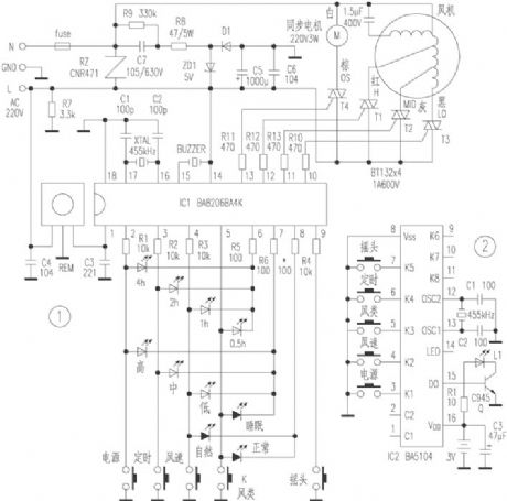
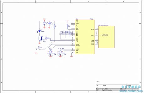
Figure 1 is the receiving board control circuit diagram, because it uses ventilator specific IC BA8206BA4K, and it has the functions of infrared receive amplifier, decoding, timed control, LED driver, therefore it has the simple structure without debugging, which is safe and convenient, and it is easy self-restraint, so it is possible to use in transforming traditional machinery velocity modulation ventilator. 220V city electricity is limited and bucked by FUSE, C7, R8, R9, rectified by D1, voltage stabilized by ZD1, filtered by C5, C6, then it forms 5V DC voltage to provides power for the IC1 {14} foot and infrared receiver. (View)
View full Circuit Diagram | Comments | Reading(3874)
Panasonic 973 air conditioning remote control circuit diagram
Published:2011/9/16 1:11:00 Author:Rebekka | Keyword: Air conditioning remote control, Panasonic
View full Circuit Diagram | Comments | Reading(2869)
Multi-channel wireless remote control circuit(F36-F/F36-J)
Published:2011/10/19 22:34:00 Author:Rebekka | Keyword: Multi-channel, wireless remote control
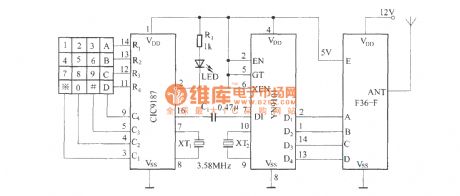
Remote control transmitter circuit.
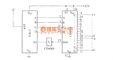
Receiver decoding circuit.
The circuit is composedof F36-F/F36-J multi-channel radio remote control circuit. In the transmitter circuit, it usesDTMF encoding and decoding circuit to turn launch four-key input signal into a binary code inputand sent out by F36-F . In the receiver circuit, F36-J will receive the remote signal and pass demodulation decoding and reduce to four binary code. Four binary code passes a four - sixteen line decoder and turn to a four - sixteen line decoder. It controls a corresponding circuit.
(View)
View full Circuit Diagram | Comments | Reading(3208)
Wireless remote control plus and minus resistor network circuit diagram
Published:2011/10/19 22:15:00 Author:Rebekka | Keyword: Wireless remote control plus , minus resistor network
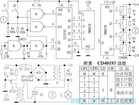
Transmitter circuit is shown in figure 1. CD40193 is a dual clock synchronous 4-bit binary up / down counter, andits function is shown as the table. CPU is the addition clock impulse input terminal, and CPD is a subtraction input of the clock pulse. When it inputs 0 to 15 pulses, its output terminals Q3 ~ Q0 change with the oder of 0000 ~ 1111 (addition) or 1111 ~ 0000 (subtraction). It is fired by the built-in antenna outside. CD4011 NAND chip is composed of two ultra-low frequency oscillators. The other two NAND gatesare the addition and subtraction counting gate. When the subtraction S1 door is open, CD40193 reduces the count. When the addition count door S2 is open, CD40193 starts the additional counts. The working voltage of CD4011 and CD40193 is 5V. Ultra-low frequency oscillator frequency is about 0.5 ~ 2Hz.
(View)
View full Circuit Diagram | Comments | Reading(2779)
Novel practical multi-channel infrared remote control switching circuit
Published:2011/10/19 22:06:00 Author:Rebekka | Keyword: Novel practical , multi-channel, infrared remote control, switching circuit
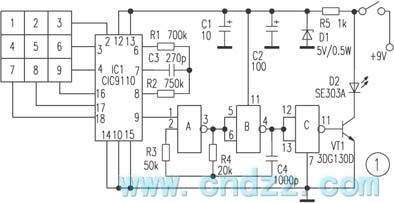
The teleswitch is reliable, and the debugging is simple, and it can realize nine-group control. It is used to remote control different household appliances and the remote control installments. The entire circuit is composed of transmission and receiving. Transmission circuit is shown in Figure 1, and the code is completed by pulse telephone number dialing integrated circuit CIC9110. When people presses down any number between“1~9”, the special-purpose pulse generator's pin ⑨ outputs high level pulse, and its speed may amount to for 20/seconds. These pulses are delivered directly to A's pin ①, its oscilation frequency approximately is 38kHz. (View)
View full Circuit Diagram | Comments | Reading(2727)
Remote control automatic door circuit diagram
Published:2011/10/19 21:21:00 Author:Rebekka | Keyword: Remote control automatic door
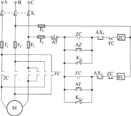
Transmitter circuit:
Receiving circuit:
The circuit controlling three-phase motor forward and reversing rotation is shown as below.
(View)
View full Circuit Diagram | Comments | Reading(4370)
Voice remote control doorbell(transceiver module composed of RCMlA and RCMlB)
Published:2011/10/19 21:25:00 Author:Rebekka | Keyword: Voice remote control doorbell
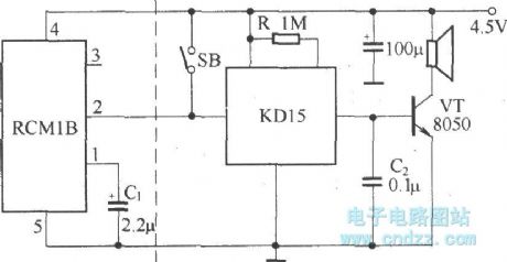
Remote control doorbell saves a connection between the placement of the doorbell and doorbell button. The place of doorbell is more convenient. Voice IC can use integrated soft KD15 series. After the installation of the circuit, it can be put into normal operation. People should keep the receiver away from large metal objects to avoidaffecting the sensitivity of remote control.
(View)
View full Circuit Diagram | Comments | Reading(1319)
The design of 315M remote control circuit
Published:2011/10/18 1:45:00 Author:Rebekka | Keyword: remote control circuit design
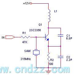
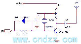

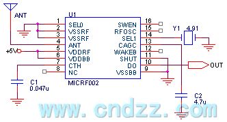
ICRF002 uses ceramic resonators to replacethe different resonator. The receiving frequency can cover 300-440MHz. MICRF002 has two operating modes: scan mode and fixed mode. Scan mode accepts bandwidth of several hundreds of KHz. This mode is mainly used to support the use of LC oscillator transmitter. Because LC transmitting frequencyis higher. In the scan mode, the data communication rate is 2.5K Bytes per second. Bandwidth of fixed pattern is only a few dozens of KHz, and it uses this mode for the supporting of transmitter crystal frequency. Stabilization data rates is up to 10KBytes per second. In addition, the use of wake-up function can wake up decoder or CPU. It can minimize the power consumption. MICRF002 is a complete single-chip superheterodyne receiver circuit. It basically realizes the antenna input after data directly output . Generally the receiver distance is 200 meters. (View)
View full Circuit Diagram | Comments | Reading(2272)
Infrared remote control code decoding circuit composed of ED5026/5027
Published:2011/10/18 1:39:00 Author:Rebekka | Keyword: Infrared remote control, code decoding circuit
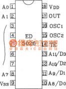
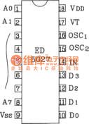
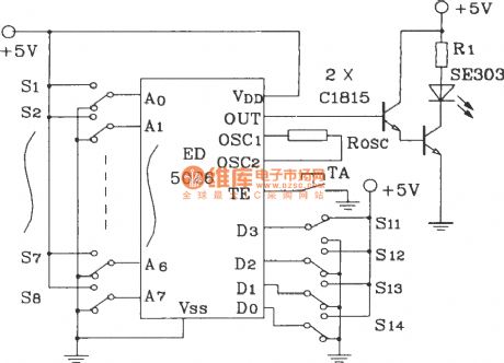
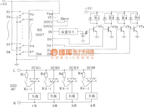
CMOS ED5026/5027 is a type of large-scale digital encoding / decoding ASIC. ED5026 is 8-bit code transmitter (can be extended to 12 bits), and ED5027 is 12-bit information receiving address.They constitute the infrared remote control system. They may also constitutethe radio, ultrasonic remote control mode. Rain gear made extensive application. Similar models are: VK5026/5027,YYH26/YYH27/YHH28 etc.
The following figure shows infrared remote control transmitter / receiver application circuit (remote control four kinds of electrical appliances) composed of ED5026/5027:
(View)
View full Circuit Diagram | Comments | Reading(1384)
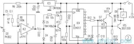
Wireless remote control electronic detonator circuit
Published:2011/10/23 21:32:00 Author:May | Keyword: Wireless remote control, electronic detonator
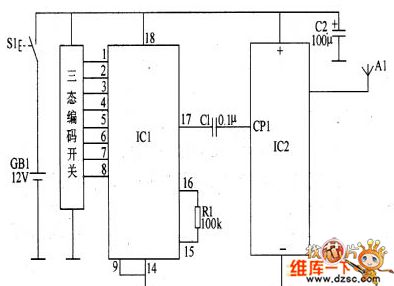
Circuit working principleThis wireless remote control electronic detonator circuit consists of wireless remote control transmitting circuit and wireless receiving detonating circuit.Wireless remote control transmitting circuit consists of control button S1, battery GB1, wireless encoding integrated circuit IC1, wireless transmitting integrated circuit IC2, resistor R1, transmitting aerial A1 and capacitors C1, C2, and it isshow in the diagram 1.
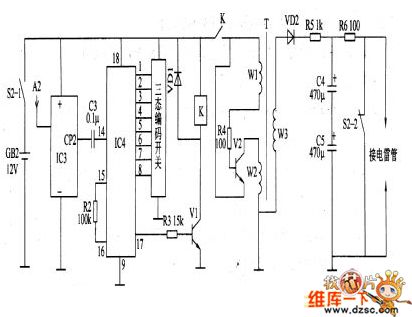
Wireless receiving detonation circuit consists of power switch S2(S2-1, S2-2), battery GB2, receive aerial A2, wireless receive intergared circuit IC3, wireless decode interated ciruit IC4; resistors R2-R6, capacitors C3-C5, transistors V1 and V2, relay K and transofrmer booster T, and it isshown in the diagram 8-28. Among them, A2, IC3, IC3, C3, R2, R3, VD1, V1 and K make up wireless receiving control circuit; R4, V2 and T make up oscillation voltage booster circuit; VD2, R5, C5 and R6 make up charge-discharge circuit.
(View)
View full Circuit Diagram | Comments | Reading(4969)
| Pages:2/34 1234567891011121314151617181920Under 20 |
Circuit Categories
power supply circuit
Amplifier Circuit
Basic Circuit
LED and Light Circuit
Sensor Circuit
Signal Processing
Electrical Equipment Circuit
Control Circuit
Remote Control Circuit
A/D-D/A Converter Circuit
Audio Circuit
Measuring and Test Circuit
Communication Circuit
Computer-Related Circuit
555 Circuit
Automotive Circuit
Repairing Circuit