
Remote Control Circuit
Index 19
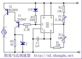
Simple motor speed governor
Published:2011/6/15 1:59:00 Author:TaoXi | Keyword: Simple, motor, speed governor
Related components (View)
View full Circuit Diagram | Comments | Reading(1918)
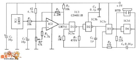
Simple artificial intelligence temperature control circuit
Published:2011/6/13 20:28:00 Author:TaoXi | Keyword: Simple, artificial intelligence, temperature control
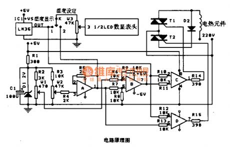
This circuit uses the LM35 voltage type integrated temperature sensor, so that the circuit becomes very simple.
The LM35 is designed as one kind of internal circuit integrated temperature sensor which has been corrected, the output voltage is proportional to the celsius temperature, the linearity is good and the sensitivity is high, also it has the moderate precision, the output sensitivity is 10.0MV/℃, the precision is 0.5℃. The measurement range is -55 to +150℃. In the stationary temperature, the self-heating effect is low (0.08℃). The operating voltage is wide, and it can work in the power supply voltage of 4 to 20V with less consumption, the operating current is less than 60 uA. The output impedance is low, when the load is 1MA, the output impedance is 0.1Ω. (View)
View full Circuit Diagram | Comments | Reading(1983)
Compressor phase protection circuit
Published:2011/7/4 0:19:00 Author:John | Keyword: Compressor
View full Circuit Diagram | Comments | Reading(1072)
The mains over-voltage protection circuit of excellent nature
Published:2011/7/3 21:55:00 Author:Borg | Keyword: over-voltage protection, mains
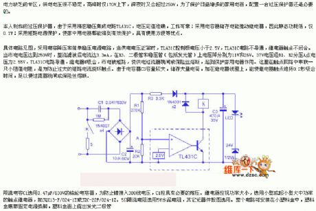
See as the figure, the circuit adopts the capacitor step-down and the simple regulated power supply circuit, when the power supply is normal, the voltage controlled by TL431C is lower than 2.5V, and TL431C is blocked, the relay is open. When the mains voltage is higher than 250V, the current which has been rectified and filtered reaches 3.3mA, the voltage drops on R3, diode and stabilivolt (including glow tube) are 11v and 26v, respectively. The 37V voltage is distributed by R1 and R2, the voltage on the distributing point is 2.55v, TL431C is conducting, the relay is pulling in, the mains is short, which make the current protector jump or the fuse blow out.
(View)
View full Circuit Diagram | Comments | Reading(1809)
The grid voltage fault protection indicating circuit
Published:2011/7/1 23:41:00 Author:Borg | Keyword: grid voltage, fault protection
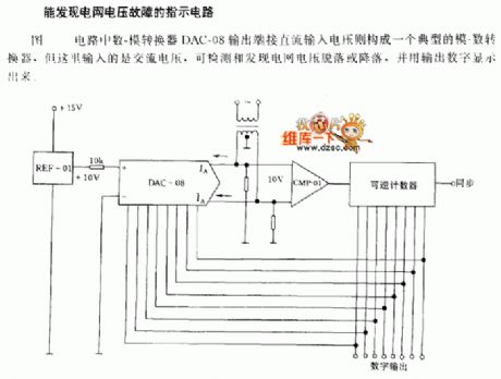
The indicating circuit of grid voltage fault discovery In the figure, the output terminal of the D/A converter DAC-08 is directly connected with the DC input voltage, which composes a typical A/D converter, but the input is an AC voltage here, which can detect and find out the grid voltage peeling or dropping, and the output digit can be displayed.
(View)
View full Circuit Diagram | Comments | Reading(939)
The over voltage/current protection circuit
Published:2011/7/2 2:49:00 Author:Borg | Keyword: over voltage/current, protection
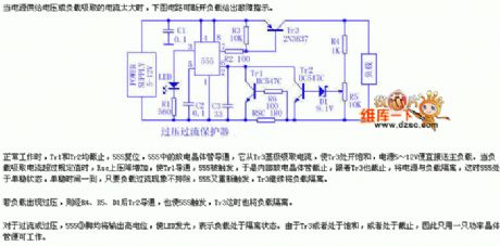
When the voltage of the power supply is too high or the load attracts too much current, the circuit in the figure can break down the load and offer fault indication.
When it is normally working, both Tr1 and Tr2 are blocked, 555 is reset, the discharging transistor in 555 is conducting, it attracts power from Tr3 basic pole, which saturates Tr3, so the 5~12V power supply is sent to the main load directly. When the load gets too much current, the voltage drop on Rsc increases, which makes Tr1 conducting, so 555 is triggered and the discharge transistor in it is blocked, then Tr3 is blocked with it, the power supply and load are separated, at the moment, 555 is in single steady state. (View)
View full Circuit Diagram | Comments | Reading(1013)
The temperature over-limit auto regulating outlet circuit
Published:2011/6/30 22:34:00 Author:qqtang | Keyword: temperature over-limit, auto regulating outlet
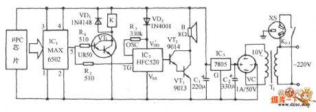
The figured circuit consists of the temperature detection switch, relay control circuit, language circuit, audio power amplifier circuit and AC step-down rectifier circuit, etc. When the temperature of the object or machine is over the set value, the outlet XS gets power and the ventilating or cooling device connected with the outlet is running. At the same time, the sound circuit is triggered and making sound, reminding people of the temperature change.
(View)
View full Circuit Diagram | Comments | Reading(1043)
The cool shutoff temperature control circuit
Published:2011/6/30 22:51:00 Author:qqtang | Keyword: temperature control
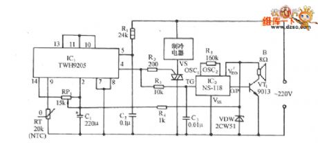
The figured circuit consists of the zero passage switch control circuit composed of TW9205 and its external elements, SCR drive system cool control circuit and sound generating circuit,etc. The figured temperature sensor RT is adopted with the backward temperature coefficient (NTC) thermistor, it is connected with the difference switch amplifier inverting input terminal (9-pin) in the TWH9205, and the forward input(13-pin) is connected with the 10-pin and 11-pin of LEV clamping pole, i.e the 13-pin is locked at a solid LEV. Adjust the value of RP1 and make TWH9205 output a low LEV in the set temperature range
(View)
View full Circuit Diagram | Comments | Reading(956)
The constant current source detecting circuit of the temperature sensor
Published:2011/6/30 22:06:00 Author:qqtang | Keyword: constant current source, temperature sensor

In the figure, when the constant current source becomes the load, the loading current will remain the same, the voltage drop of the wire resistance is a constant value, therefore, the output voltage changes in the patten of 10mV/℃. Generally, the control distance can be more than a kilometer.
(View)
View full Circuit Diagram | Comments | Reading(1324)
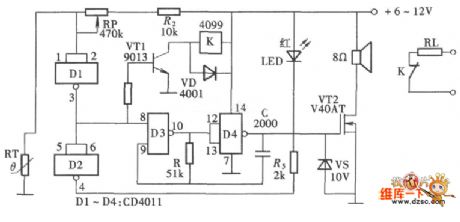
The over-temperature monitor and alarm circuit
Published:2011/6/30 21:16:00 Author:qqtang | Keyword: over-temperature, monitor and alarm circuit
The over-temperature monitor and alarm circuit is adopted with the integrated circuit temperature sensor as the test element, it only sets a upper temperature limit control point. When it is over the limit, the circuit will emitting the alarm sound to attract the user's attention. The circuit is shown in the figure, which consists of the temperature detector and over temperature monitoring circuit, alarm sound generating and output circuit.
(View)
View full Circuit Diagram | Comments | Reading(1795)
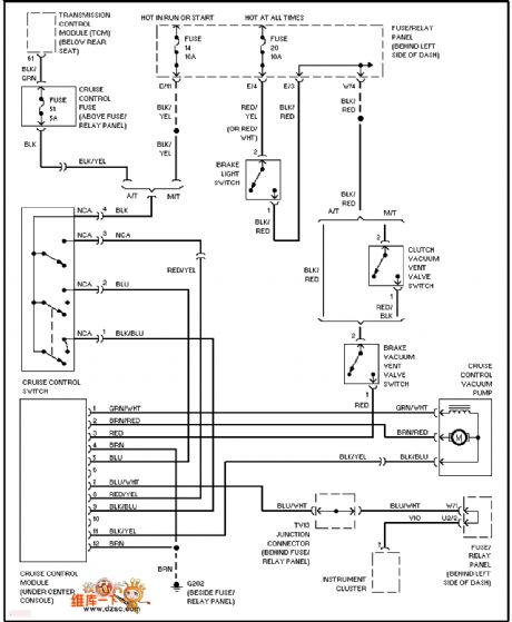
The Volkswagon cruize control circuit
Published:2011/6/30 21:17:00 Author:qqtang | Keyword: Volkswagon, cruize control
View full Circuit Diagram | Comments | Reading(929)
The temperature upper and lower limit controller circuit
Published:2011/6/30 21:40:00 Author:qqtang | Keyword: temperature, limit controller
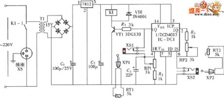
The circuit consists of one of the dual D trigger CD4013, which is simple and has the upper/lower limit temperature control function. The controlled temperature can be preset by the potentiometer, when it is over the preset temperature, the power is cut-off automatically. It can be used in heating process industrious equipment, the circuit is shown in the figure. In the circuit, the D trigger is assembled as a RS trigger, and the thermistor MF51,which is used in industrious control, is the temperature sensor.
(View)
View full Circuit Diagram | Comments | Reading(1462)
The auto ventilation and cooling down circuit
Published:2011/6/30 22:24:00 Author:qqtang | Keyword: ventilation, cooling down
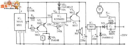
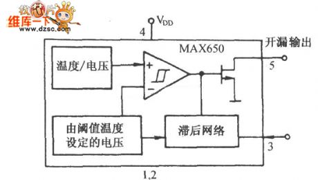
In the figure, MAX6501 is a MAX temperature switch integrated circuit which is produced by MAXIM, the USA, the temperature control range is 45~115℃.
The internal function frame circuit of MAX6501 is shown as above. (View)
View full Circuit Diagram | Comments | Reading(1029)
The auto power regulation temperature controller circuit
Published:2011/6/30 20:43:00 Author:qqtang | Keyword: auto power regulation, temperature controller
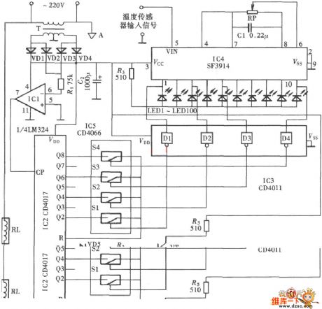
The temperature controller can adjust the input power of the heater while the LED is indicating the temperature range, which makes the controlled heater in constant working temperature state. The circuit is shown in the figure.
(View)
View full Circuit Diagram | Comments | Reading(1060)
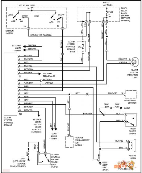
The Volkswagon anti-burglar circuit
Published:2011/6/30 20:48:00 Author:qqtang | Keyword: Volkswagon, anti-burglar circuit
View full Circuit Diagram | Comments | Reading(934)
The auto control circuit of over-temperature detection
Published:2011/6/30 21:00:00 Author:qqtang | Keyword: control circuit, over-temperature detection
The circuit consists of a NAND circuit, a detection circuit composed of thermistor and a alarm sound generating circuit, and the relay is the executing circuit. Its structure is simple and it's low-cost. The circuit is shown in the figure.
(View)
View full Circuit Diagram | Comments | Reading(982)
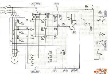
Many files optional timer circuit
Published:2011/6/28 4:07:00 Author:Fiona | Keyword: Many files optional timer
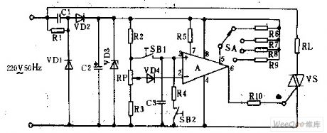
SBl is the start switch, sB2 is the stop switch. When you press the start switch SB1, the DC power supply charges the capacitor c3 through R2, the potential of integrated operational amplifier A phase input 3 is higher than the potential of reverse phase input 2, A outputs a high potential to trigger the directional Triode Thyristor VS to make the V5 conduct.AC power adds to electricity load through VS,timing power supply begins.After the release of SB1,C3 discharges by the A phase input,the length of discharging time depends on the c3's capacity,the resistance of resistors R6-R9 and the discretion of A reverse end (2) potential.
(View)
View full Circuit Diagram | Comments | Reading(988)
Infrared remote control switch circuit
Published:2011/6/29 5:59:00 Author:Fiona | Keyword: Infrared remote control switch
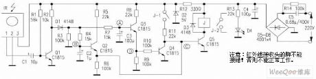
The remote control transmitter which is used is ordinary home appliance remote control.Receiveing control circuit is welded according to the figure,it can be successful without debugging.IR is infrared remote control receiving head,when the infrared signal is not received,① pin outputs the high level;when the infrared signal is received,① pin outputs a series of low level pulse.R4,C2 and R7,C3 compose two integrating circuit, Q4, Q5.J compose the relay control circuit.C5, D5 ~ D8 compose exchange step-down rectifier circuit.Usually original state after standby or power up is:Q1 conducts,Q2 is closed,Q5 is closed,the relay J does not work.
(View)
View full Circuit Diagram | Comments | Reading(1132)
The simple constant temperature control circuit
Published:2011/6/30 20:31:00 Author:qqtang | Keyword: constant temperature, control circuit
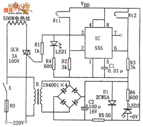
In the figure is the simple constant temperature control circuit, this controller consists of the step-down rectifier circuit, temperature sensor and RS trigger control circuit and so on. The step-down rectifier circuit power supply circuit outputs the +6v voltage. The temperature sensors of Rt1 and Rt2 is modified from a sun light lamp starter, of which Rt1 controls the lower limit value while Rt2 controls the upper limit value of the temperature, and the thermometer is used to adjust the interval. When the power is on, due to the LEV on 5-pin and 6-pin but the high LEV of 3-pin, the dual-way SCR is triggered and conducting.
(View)
View full Circuit Diagram | Comments | Reading(2557)
The RC trigger single-way thyristor dimmer circuit
Published:2011/6/30 3:54:00 Author:Seven | Keyword: RC trigger, single-way thyristor, dimmer
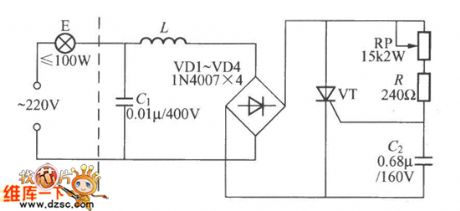
In the figure is the single-way thyristor dimmer circuit whose trigger circuit is composed of RC elements, the 220v AC is rectified by VD1~VD4 and becomes a DC impulse voltage, and then it is added between the positive pole and passive pole of the thyristor VT. RP, R and C2 compose the trigger circuit, the DC pulse voltage is charging C2 through RP and R, when it reaches a certain value, the thyristor VT is open and the bulb E is glowing because of getting power. When the impulse voltage between the two poles of of VT is over zero, VT is broken down automatically, and the power supply charges C2 through RP and R again.
(View)
View full Circuit Diagram | Comments | Reading(3869)
| Pages:19/34 1234567891011121314151617181920Under 20 |
Circuit Categories
power supply circuit
Amplifier Circuit
Basic Circuit
LED and Light Circuit
Sensor Circuit
Signal Processing
Electrical Equipment Circuit
Control Circuit
Remote Control Circuit
A/D-D/A Converter Circuit
Audio Circuit
Measuring and Test Circuit
Communication Circuit
Computer-Related Circuit
555 Circuit
Automotive Circuit
Repairing Circuit