
Remote Control Circuit
Index 13
REMOTE_CONTROL_TRANSMIITER
Published:2009/6/17 22:49:00 Author:May
This transmitter sends an FM signal in the 88-to 108-MHz range, with a tone of 19 kHz. This can be used to activate the FM MPX pilot carrier indicator, which can be interfaced to external devices. L4 is for use with a 15 CM wire antenna. L1 is 9 turns of #26 enamelled wire on a 1/4-W 10-kΩ resistor (carbon type), L2 is 2 turns wound over L1. L3 is 7 turns of #26 enamelled wire on a 10-kΩ 1/4-W resistor. (View)
View full Circuit Diagram | Comments | Reading(1436)
VERY_SIMPLE_IR_REMOTE_CONTROL_CIRCUIT
Published:2009/6/16 22:25:00 Author:May
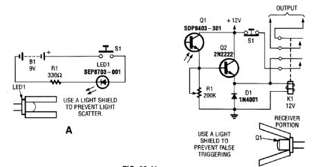
Here is a complete IR remote-control system that consists of a simple transmitter (A) and an equally simple receiver (B). (View)
View full Circuit Diagram | Comments | Reading(3018)
INFRARED_REMOTE_CONTROL_TESTER
Published:2009/6/16 22:20:00 Author:May
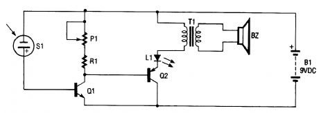
The infrared remote-control tester uses a sensitive PN-type solar sensor that is connected directly to a Darlington amplifier made up of transistors Q1 and Q2. Biasing is provided by RI and Pl, a variable resistor that serves as a sensitivity control. The collector lead of Q1 is the output lead of the Darlington amp, and it is connected to a red LED and the primary of transformer T1. The func-tion of T1 is to convert the low-voltage output signal to a level high enough to drive a small piezo disc.That disc makes a clicking sound when the sensor picks up an infrared signal that is varying in fre-quency or amplitude. The infrared sensor will also pick up visible light. The use of an IR filter (Wrat-ton #87) is recommended.
BZ Piezo DiscL1 Jumbo Red LEDP1 2-MΩ Trimmer Resistor Q1 2N3904 TransistorQ2 2N3906 TransistorR1 270-Ω ResistorS1 Solar SensorT1 Audio Transformer (View)
View full Circuit Diagram | Comments | Reading(3450)
Using encoding and decoding IC multi-channel remote control switch circuit diagram
Published:2011/5/8 5:24:00 Author:Rebekka | Keyword: Multi-channel remote control switch
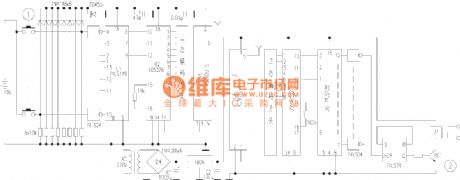
This article describes the NC multiple switch that composed of eight key remote control and receiver with eight relay. The device uses a high stability of dedicated wireless transceiver modules, and remote control encoder / decoder ICs with high security, remote control distance, performance, reliability and low static power consumption. You can use the remote control of the eight home appliances switch. CNC multi-channel remote control switch circuit is shown in figure 1. The remote control is composed of three integrated components. Circuit U1 (74LS148) is the 8-3 line of code integrated circuit, it can code the eight switch signals into BCD code output. U2 (VD5026) special code is the remote control integrated circuit. The IC has a total of 8-bit address code, 4-bit data code. This circuit uses the three data code only. The 8-bit address code can be combined freely. It means to connect the positive and negative power supply or the three encoding states composed of floating. There are 6561 kinds of different coding states to distinguish different devices. U3 (YG300U-S) is the wireless transmitter module. (View)
View full Circuit Diagram | Comments | Reading(1934)
Wireless remote control switch circuit 5
Published:2011/5/8 21:53:00 Author:Rebekka | Keyword: Wireless remote control switch
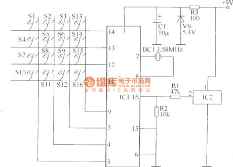
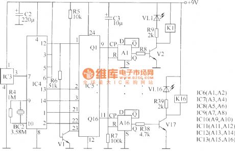
Wireless remote control transmitter circuit is composed of control buttons S1 ~ S16, resistors R1 ~ R3, capacitor C1 regulator diode VS, crystal oscillator BC1, DTMF encoder IC IC1 and IC2 wireless remote control transmitter integrated circuit components. It is shown as above.
Components selectionR1, R2 and R4, R6 ~ R39 use 1/4W carbon film resistors or metal film resistors; R3 and R5 use 1/2W metal film resistors. C1 ~ C3 use 16V voltage aluminum electrolytic capacitors. VS uses 1/2W, 5.1V voltage regulator diode silicon. VL1 ~ VL16 use φ3mm common light-emitting diodes.V1 uses S9013 type silicon NPN transistor; V2 ~ V17 use C8050 or S8050, 3DG8050 silicon NPN transistor. IC1 uses UM95087 type phone with a selection of DTMF dialing code integrated circuits; IC2 uses HS101 type wireless remote control transmitter thick-film integrated circuits; IC3 uses HS201 type wireless remote control receiver thick film integrated circuit; IC4 uses MC145436 type telephone with DTMF decoder integrated circuits; IC5 uses CD4514 or MC14514 type 4-16 line decoder IC; IC6 ~ IC13 (D1 ~ D16) use CD4013 dual D flip-flop integrated circuits.
(View)
View full Circuit Diagram | Comments | Reading(3227)
Wireless remote control switch circuit 4
Published:2011/5/8 22:05:00 Author:Rebekka | Keyword: Wireless remote control switch
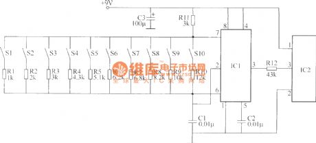
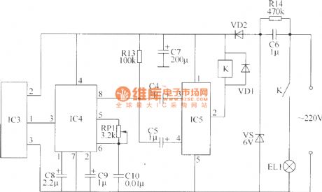
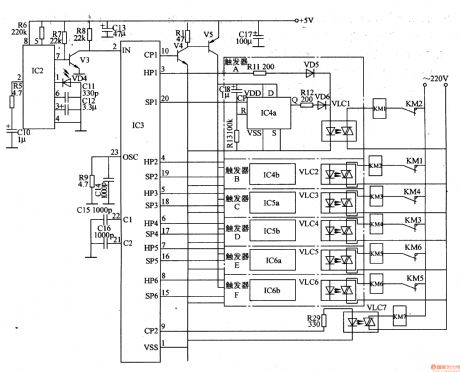
The wireless remote control switch circuit is composed of the wireless remote control transmitter circuitry and wireless remote control receiver control circuit. Wireless remote control transmitter circuit is composed of the controlled variable frequency oscillator and a wireless remote control transmitter circuit. It is shown as above.
Component selectionR1 ~ R14 use 1/4W carbon film resistors or metal film resistors. RP1 uses WSW type organic solid fine resistors. C1, C2 and C10 use monolithic capacitors; C3 ~ C5 and C8, C9 use aluminum electrolytic capacitor voltage 16V; C7 uses electrolytic capacitors voltage 25V; C6 uses 400V voltage polyester capacitor or CBB capacitors. VD1 and VD2 use 1N4007 type silicon rectifier diode.VS uses 1W, 6.2V silicon voltage regulator diodes. IC1 uses NE555 type base integrated circuit; IC2 uses TDC1808 type wireless remote control transmitter IC module; IC3 uses TDC1809 type wireless remote control receiver IC module; IC4 uses LM567 type audio PLL decoder IC; IC5 uses DM21 type dual steady-state driver IC module. K uses 6V DC relay. S1 ~ S10 use moving micro-Hop (open) button. (View)
View full Circuit Diagram | Comments | Reading(3187)
Digital code remote control switch circuit diagram
Published:2011/5/9 1:12:00 Author:Rebekka | Keyword: Digital code remote control switch
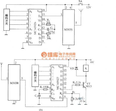
Digital code remote control switch circuit composed of digital codec MC145026/MC145027 andtiny radio transceivers M303S/M303R is shown as above.
Press the transmitter button SA, the circuit start to work. The serial encoded signal outputs from MC145026 to 15 feet, passes the transmitter module M303S and shoots out. The receiver module M303R of receiving circuit receives the encoded signals and sends to the decoder MC145027. When the address code of the encoder and decoder are exactly the same, the decoding of MC145027 effectively instructs a high-side output pulse signal. The transistor VT turns on, the drive relay pulls in. The switch control function will be completed.
(View)
View full Circuit Diagram | Comments | Reading(4454)
The switch shut off time delay circuit diagram
Published:2011/5/8 7:10:00 Author:Rebekka | Keyword: The switch shut off time delay
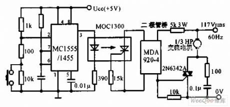
The switch shut off time delay circuit is shown as below. The switch shut off time delay circuit is composed of the timer, optocouplers, bridge SCR, SCR AC switch. When the control button is released, the keeping motor or other AC start power for 1 hour. Button closure. 2 pin voltage step-down Ucc / 3 below. The output pin 3 rises. LED lights. The bridge SCR AC switch TRIAC triggers the motor to run. The 7 feet of the capacitor began to charge at the same time. When the voltage rises to 2Ucc / 3 and the timer output decreases, the motor stops running. (View)
View full Circuit Diagram | Comments | Reading(4924)
Wireless remote control switch circuit diagram 1
Published:2011/5/8 21:37:00 Author:Rebekka | Keyword: Wireless remote control switch

This example describes a miniature wireless remote control transmitting and receiving wireless remote control switch device fabrication. It has a simple circuit, easy to build, debug and convenient. It can be used for short pulse trigger circuit or control the work of electrical equipment (such as electric curtains, Electric shutter doors, electric toys, etc.).
Select optional components R1 ~ R4 use 1/4W carbon film resistors or metal film resistors. RP uses solid variable resistors. C1 ~ C5 use monolithic capacitors. VD1 ~ VD3 use 1N4148 silicon switching diodes. V uses S8050 or C8050, 3DG8050 silicon NPN transistor.IC1 uses 630-type integrated wireless remote control transmitter T head; IC2 uses NE555 type base integrated circuit; IC3 uses IC1 supporting T631 type wireless remote control receiver; IC4 uses LM567 type based decoding IC. S uses moving together (normally open) type button. K uses 6V DC relay. The contact current capacity electrical power can be controlled.
(View)
View full Circuit Diagram | Comments | Reading(3755)
Improved one-shot timer circuit composed of 2 PUT
Published:2011/5/8 11:11:00 Author:Rebekka | Keyword: Improved one-shot timer
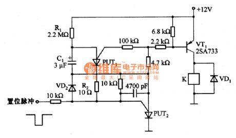
Figure 1 is an improved trigger timing circuit composed of 2 PUT. If you add the set signal, the circuit will be set, transistor VT1 turn to the conduction state, the relay K will be energized action. It supplies voltage for the delay voltage at the same time. Therefore, the capacitor is charged by C1. PUT1 is conducted by positive voltage. C1 passes PUT1, R2, and VD2 discharges. VD2 turn to positive voltage and stops the anode - gate of positive PUT. The circuit resets. R2 is used to limit the discharge current of C1, and extend the time of anti-bias gate of anode PUT. Because the circuit uses a reverse bias reset signal and the signal is not added to the PUT2 anode - cathode. The mutation voltage has no effect to load circuit. Follow the device parameters shown in the figure. The single-trigger time is about 5s, adjust the value of resistance R1 can change the regular time. (View)
View full Circuit Diagram | Comments | Reading(2281)
The remote control e-hoist circuit (1)
Published:2011/7/22 20:13:00 Author:qqtang | Keyword: remote control, e-hoist circuit
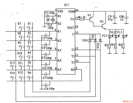
The infrared emitter circuit consists of the infrared emitter encoding integrated circuit IC1 and the external elements, see as figure 8-113. The control key S1-S4, diode VDl-VD3, capacitor C3-C8 and 4-13 pin of IC1 compose the key control input circuit; the capacitors of C1 and C2, quartz crystal oscillator BC and the 2- and 3-pin of IC1 compose the oscillator circuit; the resistor Rl-R4, transistors of V1 and V2, infrared LED VL1-VL3 and 15-pin of IC1 compose the infrared drive circuit.
(View)
View full Circuit Diagram | Comments | Reading(1711)
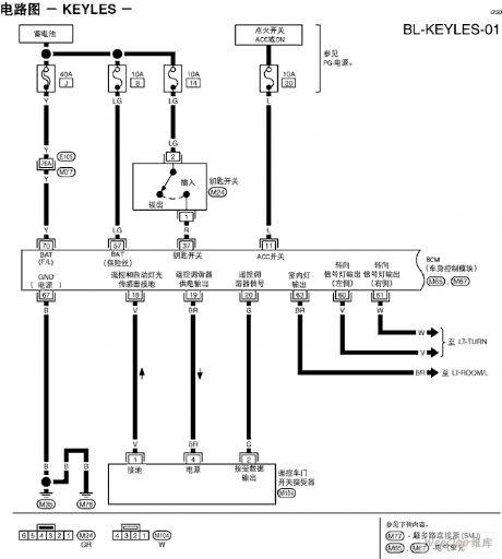
Tiida-BL remote control door system circuit
Published:2011/7/14 23:17:00 Author:Fiona | Keyword: remote control, door system
View full Circuit Diagram | Comments | Reading(982)
relay drive circuit on low power supply voltage
Published:2011/7/14 23:16:00 Author:Fiona | Keyword: relay drive, low power supply voltage
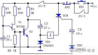
V1 is unijunction transistor BT33C,it composes the relaxation oscillator with R1, R2, R3 and C1,SCR is one-way controlled silicon,when press the start button AN1,the circuit is energized,because the SCR has no trigger voltage,the circuit is not conducted,the relay J doesn't move,the power charges the capacitor C2 to close to supply voltage through R4 and VD1(Vcc-VD1 drops).Meanwhile,the power R1 charges the capacitor C1. After a few seconds,the C1's voltage is charged to close to the trigger voltage of V1, C1 discharges immediately through V1 and forms a positive pulse on the R3, this pulse is all the way added to the V2 base to make the V2 be quickly saturated conducted,V2 collector namely capacitance C2 positive closes to ground.
(View)
View full Circuit Diagram | Comments | Reading(1248)
Photoelectric coupling type TV remote shutdown circuit diagram
Published:2011/7/17 21:51:00 Author:zj | Keyword: Photoelectric coupling type, TV remote shutdown
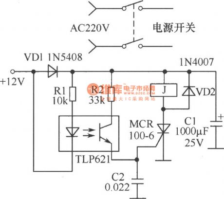
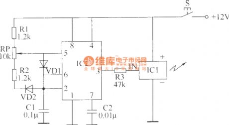
Photoelectric coupling type TV remote control and shutdown circuitis shown in the diagram. 12V powerin the circuitisfrom the control switching power supply controlledby remote control circuit in the machineor +12V voltage output terminal produced by line circuit. After starting up, + 12V voltage chargeto C1 through the VD1.Optical coupler internal light emitting diodes is cut-off state, so the thyristor is not conductive. The power switch is self-locking and TV works normally.
(View)
View full Circuit Diagram | Comments | Reading(1728)
Alternating Current Electronic Relay Circuit
Published:2011/7/20 20:35:00 Author:Sue | Keyword: Alternating Current, Electronic Relay
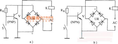
As seen in figure a), the collector isnegative while the emitter is positive. For PNP-type tube, power supply with such polarity is normal working voltage.
As seen in figure b), the collector is positive while the emitter is negative. For NPN-type tube, power supply with such polarity is normal working voltage. (View)
View full Circuit Diagram | Comments | Reading(1274)
The electric thermometer circuit composed of LM134
Published:2011/7/20 0:10:00 Author:Borg | Keyword: electric thermometer
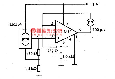
This is the electric thermometer circuit composed of LM134. In the circuit, the voltage or current output by LM134 is in proportion to the thermodynamics temperature, which can be read out on the 100μA meter, the test temperature range of the meter is -55一150℃. The power supply can work even when the voltage is under 1V, but when the precision requirement is high, the power supply should be 1.5V. When the power supply voltage is in the range of 1·5-1·2V, the inaccuracy is about 1℃.
(View)
View full Circuit Diagram | Comments | Reading(2211)
SAA3027 general infrared remote control launch circuit
Published:2011/7/20 8:02:00 Author:Christina | Keyword: general, infrared, remote control, launch circuit
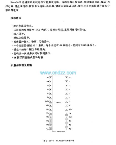
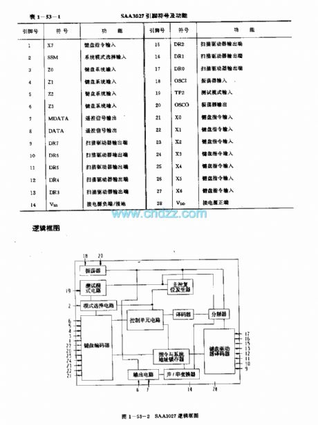
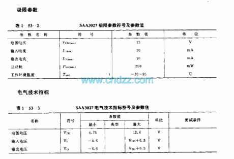
The SAA3027 is designed as one kind of general infrared remote control launch circuit. The internal circuit is composed of the oscillator, the test mode circuit, the mode selection circuit, the keyboard encoder, the control unit circuit, the decoder, the keyboard driver decoder, the instruction and system address latch and the frequency divider.
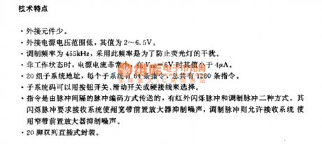
Features
Low voltage power supply, the power consumption is very small,It uses the dual-phase launch technology, the launch time is short,The input protection,The simple test mode,The oscillator is connected with the LC frequency stabilizer, there is no need of the crystal oscillator,Every button of the keyboard is the single-pole switch,28-pin dual-row DIP plastic package.
(View)
View full Circuit Diagram | Comments | Reading(999)
SAA3007 infrared remote control launch circuit
Published:2011/7/20 8:32:00 Author:Christina | Keyword: infrared, remote control, launch circuit
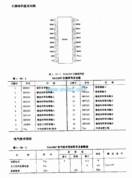
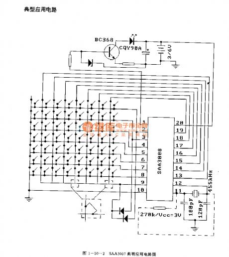
Features
The little external components.The low external power supply voltage, the value is 2-6.5V.The modulation frequency is 455kHz, we can use this frequency to prevent the interference of the fluorescent lamp.In the non-operating state, the power supply current is very small, the value is lower than 4uA when VDD=6V.It has 20 groups of subsystem addresses, every subsystem has 64 instructions.The instruction is transmitted with the pulse intermission pulse coding method, there are two methods: the infrared flash pulse and the modulating pulse. The infrared flash pulse requires the receiving system to use the broadband preamplifier to restrain the noise, the modulating pulse allows the receiving system to use the narrowband preamplifier to restrain the noise.The 20-pin dual-row DIP package.
(View)
View full Circuit Diagram | Comments | Reading(1651)
SAA3008 infrared remote control launch circuit
Published:2011/7/20 8:23:00 Author:Christina | Keyword: infrared, remote control, launch circuit

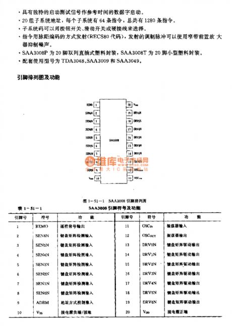
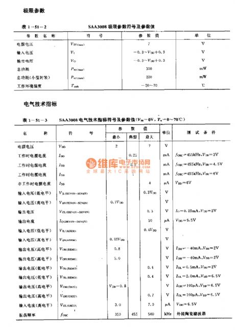
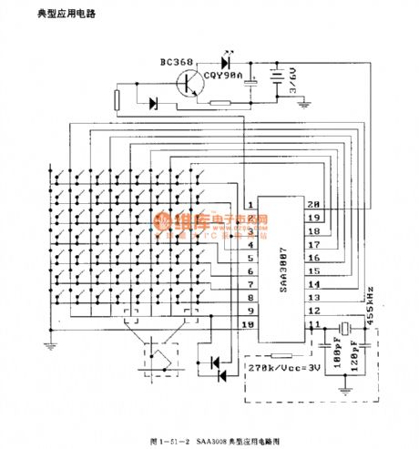
Features
The little external components.The wide external power supply voltage range, the value is 4-6.5V.The oscillating circuit has the external ceramic filter. The typical value of the reference frequency is 455kHz, the carrier-wave frequency is 1/12 of the reference frequency.In the non-operating state, the power supply current is very small, the value is lower than 4uA when VDD=6V.It has 20 groups of subsystem addresses, every subsystem has 64 instructions.The SAA3008P uses the 20-pin dual-row DIP plastic package, the SAA3008T uses the 20-pin small size plastic package.The matching model are TDA3048, SAA3009 and SAA3049.
(View)
View full Circuit Diagram | Comments | Reading(1912)
Old electric fan remote control modification
Published:2011/7/25 21:03:00 Author:Christina | Keyword: Old, electric fan, remote control, modification

(1).Remote control receiving circuit: the circuit is composed of the infrared receiver REC and the IC1 (555), in peacetime the output port of REC has the high level.
(2).Normal wind control: when the power is connected, the on-clear circuit of IC2 makes the Q0 has the high level, and the LED1 which is connected with it is lighted.
(3).Natural wind control: When you press the remote controller the 4th time, the Q4 of IC2 has the high level, the multivibrator which is composed of the IC3(555) starts oscillating.
(4).Sleep wind control: When you press the remote controller the 5th time, the Q5 of IC2 outputs the high level, the 3DG12 conducts, the J1 operates, the J1-1 closes.
(View)
View full Circuit Diagram | Comments | Reading(1149)
| Pages:13/34 1234567891011121314151617181920Under 20 |
Circuit Categories
power supply circuit
Amplifier Circuit
Basic Circuit
LED and Light Circuit
Sensor Circuit
Signal Processing
Electrical Equipment Circuit
Control Circuit
Remote Control Circuit
A/D-D/A Converter Circuit
Audio Circuit
Measuring and Test Circuit
Communication Circuit
Computer-Related Circuit
555 Circuit
Automotive Circuit
Repairing Circuit