
Remote Control Circuit
Index 5
Multi-functional infrared remote controller 555, MC1558
Published:2011/9/4 20:45:00 Author:TaoXi | Keyword: Multi-functional, infrared, remote controller
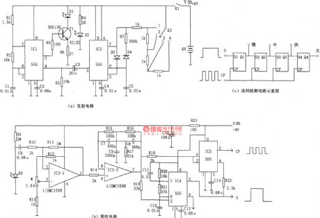
The multi-functional infrared remote controller is as shown in the figure. This circuit is composed of the infrared pulse launch circuit and the infrared receiving circuit. The infrared transmitter is as shown in figure (a), it is composed of two multivibrators which use the time-base circuit 555 as the core. The oscillation frequency of the multivibrator which is composed of the IC1(555) and R1, R2, C1 is f=1.44/(R1+2R2)C1, the corresponding frequency of the parameters in the figure is about 3kHz, the signal can be used to drive the carrier wave of the infrared emission diode D1. Another multivibrator is composed of the IC2(555), C5, R7 and the resistor which is connected with the switch K2, it can be used in the keying coding application. The output pulse waveform adds to the pin-4 of IC1 that can be used as the keying modulation signal.
(View)
View full Circuit Diagram | Comments | Reading(2028)
TC1948P video tape recorder infrared remote control launch circuit
Published:2011/9/4 20:31:00 Author:TaoXi | Keyword: video tape recorder, infrared, remote control, launch circuit
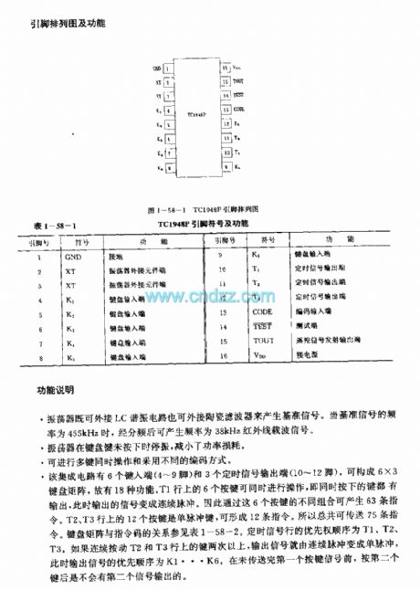
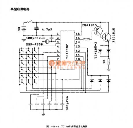
The TC1948P is designed as one kind of infrared remote control launch circuit that can be used in the video tape recorder application. The internal circuit is composed of the keyboard input circuit, the oscillator, the timing signal generator, the code signal generator, the decoder, the synchronous/single pulse signal generator and the output signal. The difference between the M50115P, M50115AP, M50115BP and M50115CP is the identification number.
Features
CMOS technology, the power consumption is low.The power supply voltage operating range is wide, and it can work in low voltage.16-pin dual-row DIP plastic package.
Function description
This oscillator can be connected with the LC resonant circuit and the ceramic filter to produce the reference signal.The oscillator will stop working when the button is not pressed to reduce the power consumption.
(View)
View full Circuit Diagram | Comments | Reading(1904)
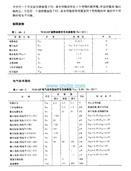
TC9132P remote control transmission line circuit
Published:2011/9/8 19:53:00 Author:TaoXi | Keyword: remote control, transmission line
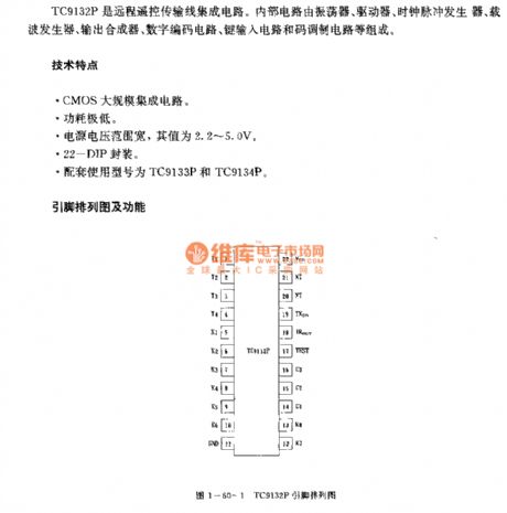
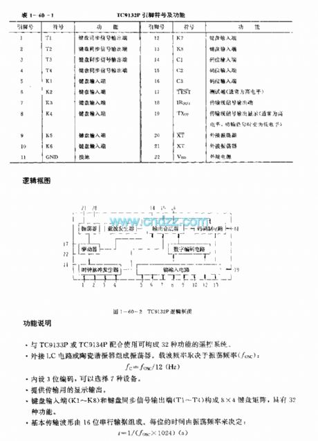
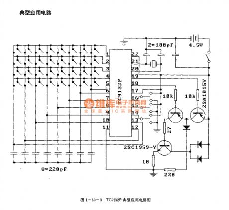
The TC9132P is designed as one kind of remote control transmission line circuit. The internal circuit is composed of the oscillator, the driver, the clock pulse generator, the carrier frequency generator, the output synthesizer, digital coding circuit, key input circuit and the code modulation circuit.
Features
CMOS large scale integrated circuit.The power consumption is low.The power supply voltage range is wide, the value is 2.2-5.0V.The 22-DIP package.The matching models are TC9133P and TC9134P.
Function description
It forms the remote control system which has 32 kinds of functions with the TC9133P or TC9134P.It forms the oscillator with the LC circuit or the ceramic resonator. The carrier frequency depends on the oscillation frequency.It supplies the display output.
(View)
View full Circuit Diagram | Comments | Reading(1648)
TC9012F TV, VCR and CD player infrared remote control launch circuit
Published:2011/9/4 20:32:00 Author:TaoXi | Keyword: TV, VCR, CD player, infrared, remote control, launch circuit
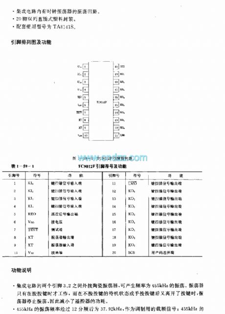
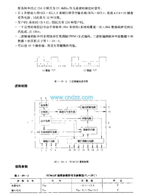
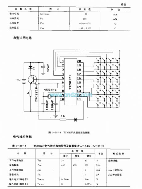
The TC9012F is designed as one kind of infrared remote control launch circuit that can be used in the TV, VCR and CD player applications. The internal circuit is composed of the oscillator, the frequency divider, the timing circuit, the system code latch circuit, the key input circuit, the key scanning output circuit, the output control circuit, the carrier signal generator, the control circuit and the data register.
Features
It uses the CMOS technology.The power voltage is low, the value is 2-4V.The power consumption is low. The current is lower than 20mA when this deivce is operating; and in the holding state, the current is lower than 1uA.Higher emission efficiency, the duty ratio of the LED is 1.8%.It has the emission display output port.The IC has the oscillation circuit with the clock oscillator.20-pin dual-row DIP plastic package.The matching model is TA8141S.
(View)
View full Circuit Diagram | Comments | Reading(1663)
YN5049/YN5050 TV, VCR and stereo equipment infrared remote control launch circuit
Published:2011/9/4 20:33:00 Author:TaoXi | Keyword: TV, VCR, stereo equipment, infrared, remote control, launch circuit

Features
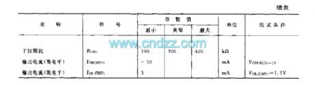
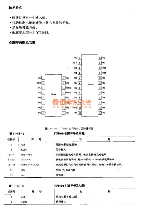
The oscillator has only one input port.The code detection circuit can prevent the interference of other circuits.It has strong noise eliminating ability.The matching model is YN5048.
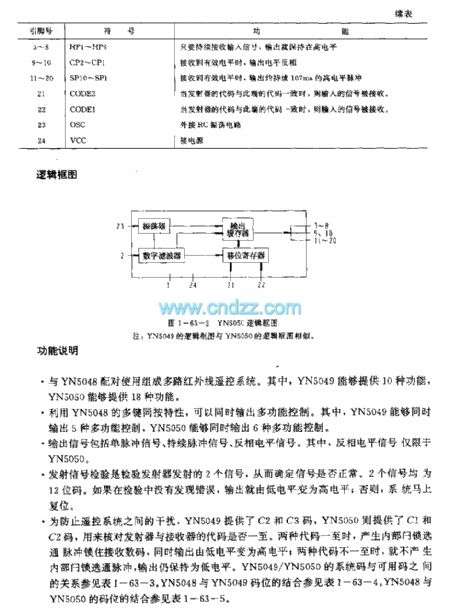
Function description
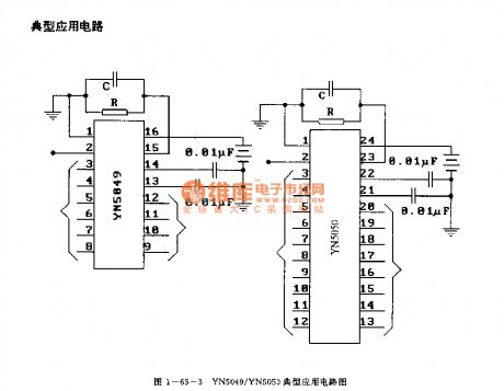
It can be used with the YN5048 to form the multi-channel infrared remote control system. The YN5049 can supply 10 kinds of functions, the YN5049 can supply 18 kinds of functions.It can output the multi-function control by using the multikey pressing-together feature. The YN5049 can output 5 kinds of multi-function controls, the YN5050 can output 6 kinds of multi-function controls.The output signal includes the single pulse signal, the continuous pulse signal, the inverse level signal.
(View)
View full Circuit Diagram | Comments | Reading(1310)
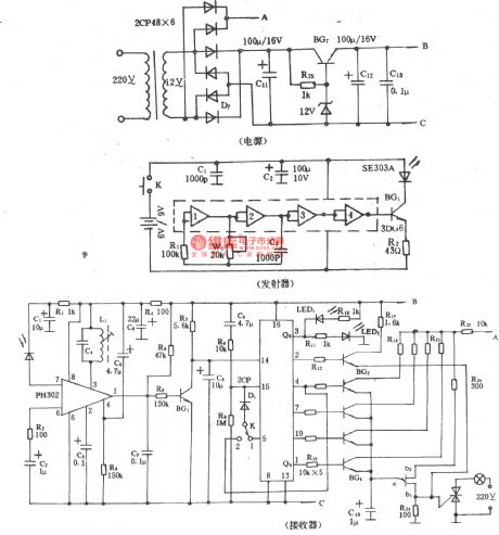
Double-channel infrared remote control switch (LM567, CD4013)
Published:2011/9/8 19:59:00 Author:Christina | Keyword: Double-channel, infrared, remote control, switch
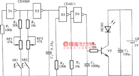
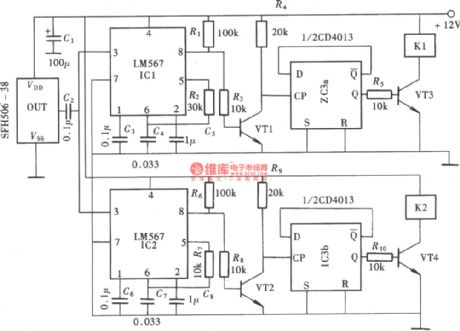
The double-channel infrared remote control switch which is as shown in the figure changes the channel control signal into the high frequency carrier frequency signal by modulating the carrier frequency signal, and it outputs the signal through the infrared transmitting tube. This kind of control mode is very helpful to resist the interference, it makes the remote control circuit more reliable, the structure of it is as shown in the figure. This circuit is composed of the double-channel infrared transmitter, the infrared receiver modem, the channel selector and the switch controller.
The emitter:
The receiver:
(View)
View full Circuit Diagram | Comments | Reading(5084)
DTMF coding multiple-channel infrared remote control switch circuit
Published:2011/9/8 20:01:00 Author:Christina | Keyword: DTMF, coding, multiple-channel, infrared, remote control, switch
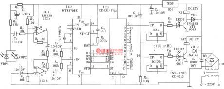
The DTMF codec is the abbreviation of the dual-tone multi-frequency codec. The multiple-channel infrared remote control switch circuit which is composed of the DTMF is as shown in the figure. It is composed of the infrared remote control signal emitter, the infrared receiving signal amplifier, the DTMF signal decoder, the 12-channel data decoding distributor and the circuit switch controller.
(View)
View full Circuit Diagram | Comments | Reading(3908)
The linear matrix CCD driver designed on the base of FPGA
Published:2011/8/31 18:57:00 Author:qqtang | Keyword: linear matrix, CCD driver, FPGA
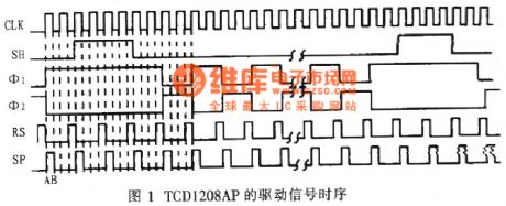
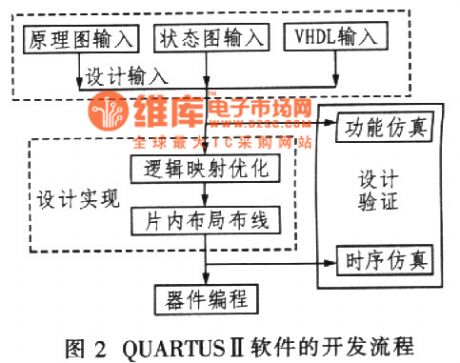
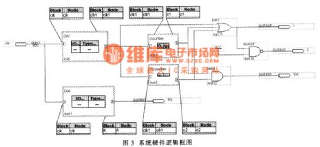
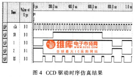
CCD(Charge Coupled Devices) characterizes small size, high precision, low power consumption, long lifespan and auto electric scanning,etx, which is widely used in image sensing and non-touching measurement arear. As the the photoelectric features, such as the switching efficiency and SNR, reach the best values only when it is under the proper sequence, then it is outputting stable and reliable signals, therefore, the design of the circuit drive is one of its key problems in application.
(View)
View full Circuit Diagram | Comments | Reading(2254)
Local area network remote control stepper motor control module
Published:2011/9/7 2:04:00 Author:Lucas | Keyword: Local area network , remote control , stepper motor, control module

In computer integrated manufacturing (CIM) or industrial automation (IA) area, many long-distance control devices have difficulty in data transmission, and its anti-interference performance is poor,when the multi-audience-bit machine is networking, the software needs to address. For this, we have developed stepper motor control module which based on local area network (Ethernet). The network controlling stepper motor control module uses TCP / IP protocol and controlling host (PC) to communicate, and the operation is stable and reliable. Each stepper motor is assigned an unique IP address, and it can do the transmission distinguish for controlling data by IP address.
(View)
View full Circuit Diagram | Comments | Reading(2394)
Remote control coding chip RT1517
Published:2011/9/7 4:26:00 Author:Vicky | Keyword: Remote control coding chip, remote control IC
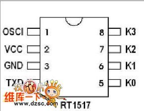
It’s a learning-code coding chip RT1517 and decoding chip for receiving
Security
1,6 million group coder
Standard 40 remote control units for learning and memorizing
Using learning-code technology
Good fault-tolerant ability
Operation
2.0 – 5.5 operating voltage
Low power dissipation
Learn-LED pin learning output indication
Auto modulation for Baud rate
Other features
Few exterior components
Being used as individual decoder
Easy to produce and no need of coding in PCB
Typical application
Auto multimedia central control system
Auto/Moto Annunciator
House security
Auto electronic lock and garage gate
Identity resolution
Anti-theft system (View)
View full Circuit Diagram | Comments | Reading(1509)
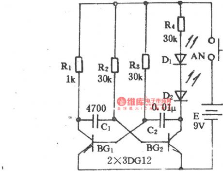
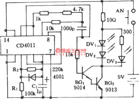
Remote control doorbell circuit diagram
Published:2011/9/5 3:31:00 Author:Lucas | Keyword: Remote control doorbell

The self-excited multivibrator is composed of the discrete components, and the oscillation frequency is mainly decided by L2, C3. The transmitting frequency is 30 ~ 40MHz gotten by the components shown as the figure. Usually, the circuit is disconnected, pressing the AN will make power on, and the circuit will emit oscillation signal. Receiver circuit: D1, D2 form the doubler circuit, which can double and rectify the signal sensed by L4, and the output signal can make BG3 saturated conduction, then the conduction will generate the negative pulse to set the time base circuit 555, and its pin 3 outputs high level to trigger the music integrated circuit IC2. BG4 is used as audio power amplifier. R3, C9 can adjust the delay time of 555.
(View)
View full Circuit Diagram | Comments | Reading(2310)
Delay pulling in relay circuit
Published:2011/8/29 2:26:00 Author:Jessie | Keyword: Delay pulling in , relay
If you want to get the delay circuit with long time and it iseasy to adjust,you should use the transistor to control relay current, and access RC on the base circuit, and the circuit is shown as the chart. If the supply voltage, capacitor, current amplification coefficient and the required pull-in power are known, you should select the appropriate relay coil resistance and voltage value in order to delay as long as possible. This time can be determined by the constant value of time.
(View)
View full Circuit Diagram | Comments | Reading(1180)
Relay delay pulling in circuit
Published:2011/8/29 1:45:00 Author:Jessie | Keyword: Relay , delay pulling in
Relay delay pulling in circuit is composedof theplane transistors BC107C, BC107B and some other external components. Since transistors have high current amplification coefficient and small collector current,the delay can reach 60s. If it requires lower, it should use the lower capacitors.
(View)
View full Circuit Diagram | Comments | Reading(940)
Electronic relay with glow numerating tube
Published:2011/8/29 1:50:00 Author:Jessie | Keyword: Electronic relay , glow numerating tube
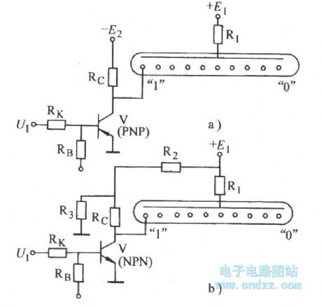
In zero negative logic system,it usesthe circuit shown as Figure a). In thezero positivelogic system is, it uses the circuit shownin Figure b. (View)
View full Circuit Diagram | Comments | Reading(3377)
The print timing exposer circuit
Published:2011/8/23 22:06:00 Author:Borg | Keyword: timing exposer
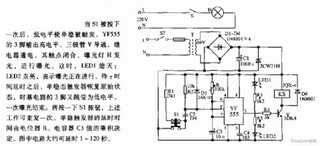
When S1 is pressed once, the low LEV triggers the single stabilizer, YF555 3-pin is outputting a high LEV, the triode V is conducting, the relay is power-on, the contactor is closed, the exposing light H is glowing and the exposure is done. At the moment, LED1 is put out. LED2 is glowing, which means the exposure is going on, after the time of T, the single stable trigger is reset, the 3-pin of the time-base circuit is turned into LEV again, and an exposure is done. By pressing key S1, the above work is repeating once.
(View)
View full Circuit Diagram | Comments | Reading(948)
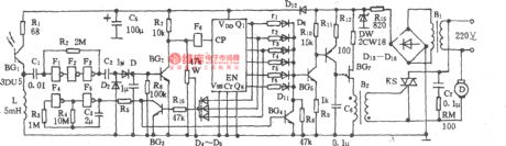
Electric fan infrared remote control circuit (1)
Published:2011/8/24 21:12:00 Author:Christina | Keyword: Electric fan, infrared, remote control
Electric fan infrared remote control circuit (1) (View)
View full Circuit Diagram | Comments | Reading(1490)
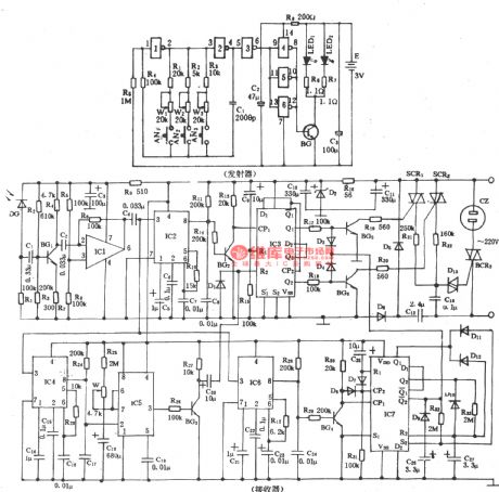
Electric fan infrared remote control circuit (2)
Published:2011/8/24 21:14:00 Author:Christina | Keyword: Electric fan, infrared, remote control
The emitter:
The receiver:
(View)
View full Circuit Diagram | Comments | Reading(1202)
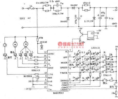
Electric fan infrared remote control circuit (4)
Published:2011/8/24 21:15:00 Author:Christina | Keyword: Electric fan, infrared, remote control
Electric fan infrared remote control circuit (4) (View)
View full Circuit Diagram | Comments | Reading(1610)
Electric fan infrared remote control circuit (3)
Published:2011/8/24 21:15:00 Author:Christina | Keyword: Electric fan, infrared, remote control
Electric fan infrared remote control circuit (3) (View)
View full Circuit Diagram | Comments | Reading(1673)
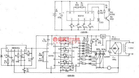
Electric fan infrared remote control circuit (5)
Published:2011/8/24 21:16:00 Author:Christina | Keyword: Electric fan, infrared, remote control
The emitter:
The receiver:
(View)
View full Circuit Diagram | Comments | Reading(1415)
| Pages:5/34 1234567891011121314151617181920Under 20 |
Circuit Categories
power supply circuit
Amplifier Circuit
Basic Circuit
LED and Light Circuit
Sensor Circuit
Signal Processing
Electrical Equipment Circuit
Control Circuit
Remote Control Circuit
A/D-D/A Converter Circuit
Audio Circuit
Measuring and Test Circuit
Communication Circuit
Computer-Related Circuit
555 Circuit
Automotive Circuit
Repairing Circuit